KT motor controllers -- Flexible OpenSource firmware for BMSBattery S/Kunteng KT motor controllers (0.25kW up to 5kW)

a friendly guy at the german mikrocontroller.net Forum has simulated our setup with LT-Spice with 5V supply voltage.

Strom_Schaltung.png


Perhaps it would be worth spending some time playing around with LT-Spice 8)

There is a little database of the motor constants of several common motors available (no inductance, just Kv and R).

regards
stancecoke
 
The newer code looks a lot faster. I'm not familiar enough with the hardware, but it looks like there's more code there than I'd expect, but that may be required by the STM8 hardware.

Let's assume for a moment that this is all correct, what could cause the current to rise as it is? If the ADC readings are incorrect (low) due to noise or timing then the current feedback loop could drive the current up? If the PWM is not changing the current should drop and then rise back to normal based on the L/R time constant.
 
Alan B said:
The newer code looks a lot faster. I'm not familiar enough with the hardware, but it looks like there's more code there than I'd expect, but that may be required by the STM8 hardware.

Let's assume for a moment that this is all correct, what could cause the current to rise as it is? If the ADC readings are incorrect (low) due to noise or timing then the current feedback loop could drive the current up? If the PWM is not changing the current should drop and then rise back to normal based on the L/R time constant.
As I did mention before:
- current rises because of a big value of duty_cycle, setup by the current controller. Current controller see a low current value and then increases the duty_cycle but happens that just after the transition, that duty_cycle is to high for the "new" low resistance value of the motor
- current readings seems to be ok as are the same I can see on my lab power supply
 
The current controller should not raise the PWM for 3-5 time constants after a commutation. It should lower it during this period if needed, but not raise it, or it could do a computed PWM peak and decay to speed up the current rise. But during at least the first couple of time constants the ADC value is not going to represent the eventual current by a large factor. One thing you might consider is to use an asymmetric gain, raise PWM slow and lower quickly.
 
Works very well now, starting with sinewave no interpolation.

I started by running the motor free, you can see the duty_cycle target and duty_cyle, as also the motor speed (motor current were ADC 12 value = 6 amps). After I applied brakes and they could full stop the motor:


And then I got courage, defined motor current were ADC 30 value = 15 amps (controller max current) and did test with the ebike and the battery (24V for now)... all went ok, didn't saw any controller reset or burned mosfet. I am confident now.

But the code don't do sinewave interpolation, which is a must. The transition from sinewave not interpolation to sinewave interpolation 60 degrees, fails -- I now need to work on this.
 
Alan B said:
The current controller should not raise the PWM for 3-5 time constants after a commutation. It should lower it during this period if needed, but not raise it, or it could do a computed PWM peak and decay to speed up the current rise. But during at least the first couple of time constants the ADC value is not going to represent the eventual current by a large factor. One thing you might consider is to use an asymmetric gain, raise PWM slow and lower quickly.
Good idea. I already tested something like that and the results were not so good -- the duty_cycle ended up not increasing as it should when increasing the throttle -- but I must say I were very tired on that time, maybe I did fail on the code. For now, I will follow the current working code.
 
I just had a look at your recent code. As far as I understand, the main difference is, that you don't switch the timer mode and run the motor with 6 Steps at start up. And now the switch from 6 step to 60° interpolation does not work?

start with 6 step
switch from 6 step to 60° interpolation at 140 erps
switch from 60° interpolation to 360° interpolation at 180 erps
fall back to 6 step is disabled at the moment

Regards
stancecoke
 
stancecoke said:
I just had a look at your recent code. As far as I understand, the main difference is, that you don't switch the timer mode and run the motor with 6 Steps at start up. And now the switch from 6 step to 60° interpolation does not work?

start with 6 step
switch from 6 step to 60° interpolation at 140 erps
switch from 60° interpolation to 360° interpolation at 180 erps
fall back to 6 step is disabled at the moment
No, new code is here: https://github.com/OpenSource-EBike-firmware/BMSBattery_S_controllers_firmware/tree/bug_very_high_current_at_startup

It is like you know already, not using 6 steps:
1. start with no interpolation sinewave (just using 6 points of the sinewave)
2. switch from sinewave 6 point to sinewave with 60° interpolation
3. switch from 60° interpolation to 360° interpolation at 180 erps

1. ok!
2. fails the transition from 1. to 2.
3. didn't tested (can't while 2. works) yet but should work
 
Very strange...

If I #define MOTOR_ROTOR_DELTA_PHASE_ANGLE_RIGHT 100, the motor starts rotating forward and after can't/fails to switch to sinewave 60º interpolation.

If I #define MOTOR_ROTOR_DELTA_PHASE_ANGLE_RIGHT 200, the motor starts rotating backwards (this is a geared motor, ebike wheel don't rotate backwards due to the motor clutch) and after the commutation speed to sinewave 60º interpolation, it quickly inverts the rotation direction to forward and runs very well with FOC, as expected.

200 is like the base 100 + another 100(180 degrees - 30 degrees).
 
O resolved the issue as I could for now, it works very well with my Q85 motor but now there are 2 different values to adjust for every motor but luckily, they may be very similar between the same type of motors:


The code is on master branch. Stancecoke, you can go ahead now and try on your EBike, but with a fuse :)
 
casainho said:
It is like you know already, not using 6 steps:
1. start with no interpolation sinewave (just using 6 points of the sinewave)

so this are 6 steps! :wink:

OK, I just tested your recent master branch with my testbench. (For a test on the bicycle the weather is too bad, rain and just 5°C in Munich)

Your code doesn't work as it is for me, just no reaction to the throttle signal. I've modified the code and put the mapped throttle value directly to the duty cycle, now the motor runs, but of course with no control loop working. The switch from 6 step to 60° interpolation works good with your values and the efficiency is OK.

regards
stancecoke
 
stancecoke said:
casainho said:
It is like you know already, not using 6 steps:
1. start with no interpolation sinewave (just using 6 points of the sinewave)

so this are 6 steps! :wink:

OK, I just tested your recent master branch with my testbench. (For a test on the bicycle the weather is too bad, rain and just 5°C in Munich)

Your code doesn't work as it is for me, just no reaction to the throttle signal. I've modified the code and put the mapped throttle value directly to the duty cycle, now the motor runs, but of course with no control loop working. The switch from 6 step to 60° interpolation works good with your values and the efficiency is OK.
Note that I tested on S12S and I guess you did you S06S :) -- if so, look at main.h. Sonce I remember, the main difference is that S12S can handle more current.

I think we can't call it 6 steps, as on that way would have 1 phase without energy everytime bit ot has the 3 phases energized with sinewave values, but just 6 different points over the 360 degrees.

A lot of sun here in Portugal and that results in a severe lack of water :-( :-( climate change problems for us :-(
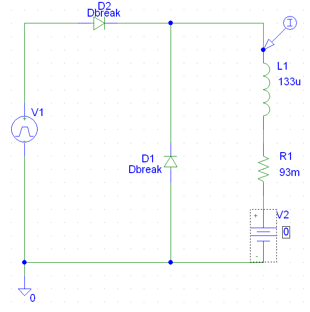
I wish to test my ebike next monday, with S12S on Q85 with 24V and on the other EBike with Q100 with 48V (isn't this motor failing??), and I need to use a fuse :)

Then I need to implement that startup with motor max current and test, if ok, I can close for now the motor code. I will be away mostly next week but I plan to be back on the next other.

I should also receive my new components as the torque sensor and try make it working on the firmware :)

As I am highly motivated to develop motor firmware for motor electric vehicles to help our planet, I will be traveling to German next week as I was invited by a company that develop electric light personal vehicles like eskates, ebikes, escooters, etc. I am really happy but that will mean I will have less time to this project. Let's see what happens but I wish to finalize a good working firmware!!

Also I am happy because I did read some news saying that Europe is pushing for electric cars not because of Tesla but because of China, because Chinese are ahead!! I want to keep participating by continue providing OpenSource knowledge and tecnhology :)
I came from my own startup about desktop 3D Printing using OpenSource technology like RepRap project that shaped the 3D Printers and is very relevant on the market.
 
You were right. If I set the controllertype to S06S, it works. There's just a little bug in the main.h. I had to modify it:

Code:
#if CONTROLLER_TYPE == CONTROLLER_TYPE_S06S
#define PWM_DUTY_CYCLE_RAMP_UP_INVERSE_STEP 30
#elif CONTROLLER_TYPE == CONTROLLER_TYPE_S12S
#define PWM_DUTY_CYCLE_RAMP_UP_INVERSE_STEP 50
#endif
#define PWM_DUTY_CYCLE_RAMP_DOWN_INVERSE_STEP 30

I wish you much success with your interview in Germany!
 
I've added a PI-control for the current to the Torque-Simulation branch now.
Code:
uint32_t PI_control (uint16_t ist, uint16_t soll)
{
  float float_p;
  static float float_i;
  float_p=((float)soll - (float)ist)*0.3;
  if (float_p>3)float_p=3;
  if (float_p<-3)float_p=-3;
  float_i+=((float)soll - (float)ist)*0.2;
  printf("soll %d, ist %d, P-Anteil %d,I-Anteil %d\n", soll, ist, (int16_t)float_p, (int16_t)float_i);
  return ((uint32_t)(float_p+float_i));
}

It works very good, you can tune the behavior of the control-loop by varying the values of the P and I factors (proportional gain is 0.3 at the moment, integral gain is 0.2).

Actually I'm struggling with the problem, that the ADC Value of the throttle is not stable sometimes. I get very much scatter then, and of course, the control loop can not work properly with this.

Regards
stancecoke
 
I've been working on a code generator for the motor commutation. This makes it easier to try different code for the motor and get it right, and make small changes that get properly implemented across all the different variations that need to exist for the different phases.

It is a python program that generates C code that you incorporate into the micro code. It uses tables for UVW and Hall signals to generate all the combinations from one template so you don't have to write all six copies, just the one.
 
Will you share that tool? Normally you set up your system by changing the hall- and phase wires by trial and error... Or are you planning a self learning procedure?

regards
stancecoke
 
stancecoke said:
Actually I'm struggling with the problem, that the ADC Value of the throttle is not stable sometimes. I get very much scatter then, and of course, the control loop can not work properly with this.
It seems that this is a problem of resonance with the lab power supply. With the battery as power supply it works without problems. Here is a plot of the control behaviour:

index.php


regards
stancecoke
 
Another test drive of 12kms, running at limited speed of 30km/h. My S12S running with my 24V battery and my Q85 24V 328 RPM motor. The ride went perfect without any fail. The startup seems very similar with original firmware.


[youtube]BTUoaUOv_OU[/youtube]

Stancecoke, maybe we can use the github issue tracker to keep a list and track of features and issues to implement and resolve -- It is easy for me to forget many little things that need to be implemented: https://github.com/OpenSource-EBike-firmware/BMSBattery_S_controllers_firmware/issues

stancecoke said:
stancecoke said:
Actually I'm struggling with the problem, that the ADC Value of the throttle is not stable sometimes. I get very much scatter then, and of course, the control loop can not work properly with this.
It seems that this is a problem of resonance with the lab power supply. With the battery as power supply it works without problems. Here is a plot of the control behaviour:
Good. And I either not having any problem with ADC readings.
Nice to see that you find a software to real time plotting :)

I can try learn with your code if you write the comments and variable names in EN, other way will be difficult. I want ASAP to start making the PAS code, as I now have one installed.
 
casainho said:
Another test drive of 12kms, running at limited speed of 30km/h. My S12S running with my 24V battery and my Q85 24V 328 RPM motor. The ride went perfect without any fail. The startup seems very similar with original firmware.
Great, I hope we have fixed the thing with the burning mosfets now!

casainho said:
I can try learn with your code if you write the comments and variable names in EN, other way will be difficult. I want ASAP to start making the PAS code, as I now have one installed.
Just ask me via PN, if I need to explain something, I fear I was not consistent all the time with using english in comments and variable names :?

regards
stancecoke
 
Bad news and I need your help

I put the S12S (after changing the drop voltage power resistor so it work on 48V) on the 48V battery and my Q100 motor. I also added a 15A fuse on the battery GND wire and the firmware controlling a max of 12A. The motor did run and when I started to test the startup torque, soon it stopped to work, by not doing any more torque... and I now remember that the other S12S just had the same symptoms when it did fail -- power mosfets seems that are not in short circuit.

I went to look with oscilloscope on the drivers signals, input lines that come from the microcontroller and the signal at power mosfets gate pins.
When microcontroller is putting out a square wave (PWM 50% duty_cycle) on the all 6 lines (3 of them with inverted PWM signal), (VBAT 48V from lab power supply) the mosfets gate pins have:
1. Q4, Q12 and Q20: square wave as expected, from 0V up to max 16V
2. Q1, Q09 and Q17: square wave from 0V up to max 64V!!

2. seems incorrect to me, as I don't see why gate pin should have even higher voltage than VBAT!! Can someone please help me find what part of the circuit is wrong? what components may be failing so I can exchange them for a new ones and test??

The full schematic is here as PDF file: https://opensourceebikefirmware.bitbucket.io/EmbeddedFiles/32-BMSBattery_S06S-Kuteng_EBike_motor_controller_schematic.pdf

Drivers stage only:
 
Wait, I just put the controller on the 24V Q85 motor but running from 48V power lab supply and it runs well the motor!! Maybe the issue is some failing of hall sensors from Q100 motor... I will need to test more.

stancecoke said:
casainho said:
2. Q1, Q09 and Q17: square wave from 0V up to max 64V!!
Seems OK to me, as these are the high side Mosfets, see "bootstrapping"
Thanks. I will need to read more and learn about this.
 
casainho said:
Wait, I just put the controller on the 24V Q85 motor but running from 48V power lab supply and it runs well the motor!! Maybe the issue is some failing of hall sensors from Q100 motor... I will need to test more.
So I connected again to Q100 and I got the same results, motor not reacting to throttle. But after some seconds there was a bad smell and I looked at the controller... the drop voltage power resistor (the correct value for 48V) were smoking and than I did quick cut the power. I guess hall sensors did fail and now probably they may be in short circuit or something and asking to much current from the controller and so the drop voltage power resistor start to burn.
I need to forget this motor. Or maybe repair the hall sensors??
 
Back
Top