how to program a sevcon gen4

Hi,
I'm doing torque control on a BLDC motor. I have some problems with getting the torque over 10 Nm. It seems like I can't get more than 50A, actual AC current (Iq,) even though I set the max amps to 100A. And the max torque is 100Nm. I'm using a battery bank, 84V, that should be able to drain a lot more. Is there some setting in DVT that I've missed to change?
Thanks!
 
frodus said:
updating the thread, since people can't figure it out after things moved on the Heinzmann site

Go here:
http://www.heinzmann.com/en/download-electric-motors/documents-software
Then navigate the tree to "Motor Controllers", then "Software" then "Sevcon Software" and click on "Sevcon Install".

You will need to login with
Username : software
Password : perm-motor2010

Hi Frodus,

Is there any chance you might have an updated username and password for the heinzmann site? Those ones posted in 2015 are no longer valid.

Regards.
 
I don't.

Basically, unless you have an OLD IXXAT cable, it won't work with that software anyway. I sell licenses and programmers at my site if you need one.
 
frodus said:
I don't.

Basically, unless you have an OLD IXXAT cable, it won't work with that software anyway. I sell licenses and programmers at my site if you need one.

Is it possible to get that software anymore? I have an old cable.
 
Hi,

I've been trying to program the Sevcon for a while, now it doesn't allow me to save a DCF or send a working DCF to unit. I've updated the firmware and still nothing. It says the Local Line contactor not mapped and Data type(15) for 4617, 1 unrecognised.

Has anyone encountered this issue, also when i try to save the current DCF it crashes.

Kind regards,
Gonçalo Olas
 
I suspect this will be a tough question to answer since there are so many experts on here with different opinions of "good enough" but I'll ask anyway.

Is it possible to get a sevcon and a motor like an ME1507 purchased together as a kit and have it just work out of the box? Most of the vendors I've seen offer them in kits so the initial programming is done but would I be dreaming to think it would actually be good enough? Basically is there a turnkey option if using a common well documented motor?

I'm in the early planning stage for converting a CR125 MX bike and the Sevcon and ME1507 seem like a good choice but I'm scared off by all the programming horror stories.

Is it matching the controller to a particular motor that requires all the effort and $$ or is it every little change? If it comes programmed for a specific motor can small things like throttle and regen ramps be adjusted without thousands more dollars worth of cables and labor? Maybe just programmed using a sevcon display?

Thanks for any guidance.
 
Has anyone been able to control a sevcon gen4 with can messages? i.e. set throttle / brake / etc. via can messages as opposed to analog signals? if so, might I ask how? (i.e. what CAN ID, what message/payload, etc.?)
 
slapshot136 said:
Has anyone been able to control a sevcon gen4 with can messages? i.e. set throttle / brake / etc. via can messages as opposed to analog signals? if so, might I ask how? (i.e. what CAN ID, what message/payload, etc.?)

Yup there is a way.

On my dual controller setup I have 1 sevcon as the master and the other is a slave getting its commands over CAN from the master.
 
hi all,

someone can help me to get my Gen4 Size6 running "WELL" with my ME1302 ?

i have no faults at he controller but the motor is running rough and slow. sounds not good. my file attached.

ThanksView attachment aktuell.rar
 
Try aligning the encoder. 9 times out of 10 that is the issue for running rough.

I emailed you the document you'll need.
 
hi all,

someone know how to change the spinning directon of a gen4 size6 wit an me1302 ?

i put switch in revers: motor turns fwd, revers switch is activated in software, rev is shown at clearviewdisplay
i put switch in fwd: motor turns rev, fwd switch is activated in software, fwd is shown at clearviewdisplay

swap sin with cos > does not work
swap M1 with M3 > does not work

any idears??
 
Can you post your wiring diagram and any screen shots. I had the same problem which I solved. The drawing I had for my ME1507 had cosine and sine labelled wrong and I had to swap the motor phase wires over.

Bernel
 
You'll have a much easier time with an oscilloscope, but it sounds like your encoder is something like 180 degrees out of alignment.

Read this: https://www.e-kart.fr/images/stories/technique/SEVCON/sevcon-app-note-pmac.pdf
If the link doesn't work, google for "sevcon app note". It explains what you're experiencing.

You probably already know, but keeping phase 1 the same, and flipping leads 2/3 will reverse the motor's direction from forward to reverse.
Next, your cos signal should lead the sin signal by 90 degrees in forward direction, so that's your order of whether or not you need to flip the sin/cos leads to the encoder. If you don't have an oscilloscope you can be very slow with a voltmeter and figure it out.

HOWEVER, if your encoder is fully 180 degrees out of alignment it can turn in the wrong direction, and sometimes it's actually rideable. BE CAREFUL though, because if you're at that point, it can be pretty unstable and race like a banshee with regenerative braking enabled and no load on the motor. This is why the scope is important to use, so you can visually see the encoder's alignment with your phases.

Finally, if everything works, and you've used a scope to guarantee it's well aligned but very rough and sounds bad, it could also be noise. (I'm still measuring PWM noise from the gen4 on my encoder as soon as the contactor closes, that throws off the position whenever I'm pulling more than 300A AC current. That's even with everything heavily shielded and shields grounded.) But it sounds like you're not at that point yet, that it's more likely just encoder alignment.
 
darseygodwin said:
You'll have a much easier time with an oscilloscope, but it sounds like your encoder is something like 180 degrees out of alignment.

Read this: https://www.e-kart.fr/images/stories/technique/SEVCON/sevcon-app-note-pmac.pdf
If the link doesn't work, google for "sevcon app note". It explains what you're experiencing.

You probably already know, but keeping phase 1 the same, and flipping leads 2/3 will reverse the motor's direction from forward to reverse.
Next, your cos signal should lead the sin signal by 90 degrees in forward direction, so that's your order of whether or not you need to flip the sin/cos leads to the encoder. If you don't have an oscilloscope you can be very slow with a voltmeter and figure it out.

HOWEVER, if your encoder is fully 180 degrees out of alignment it can turn in the wrong direction, and sometimes it's actually rideable. BE CAREFUL though, because if you're at that point, it can be pretty unstable and race like a banshee with regenerative braking enabled and no load on the motor. This is why the scope is important to use, so you can visually see the encoder's alignment with your phases.

Finally, if everything works, and you've used a scope to guarantee it's well aligned but very rough and sounds bad, it could also be noise. (I'm still measuring PWM noise from the gen4 on my encoder as soon as the contactor closes, that throws off the position whenever I'm pulling more than 300A AC current. That's even with everything heavily shielded and shields grounded.) But it sounds like you're not at that point yet, that it's more likely just encoder alignment.

thanks for your infomations!

yes the banshee effect i have had with regenerative braking^^ (the controller quits the coilpower after the motor spinns up very high)
i have a oscilloscope and align the encorder manually well.
like at this post i align the encorder (at this time I have not had gen4 but a kelly):

https://endless-sphere.com/forums/viewtopic.php?f=10&t=88647

with the kelly the motor worked ok... better then with the gen4 at the moment (maybe because i have the encoder noch aligned at the software)
 
now i got it running: align the encoder etc. (Gen4 Size6 do have mutch POWER. mutch more then Kelly 8080IPS (600A)
now my questions :

is it possible the use the Gen4 to output a Speedsignal for the Cycle Analyst?
I have mount some Halls inside the Motor but they are do not switch correctly to the speedvalue
maybe EMC noise from motor.

- i have connect a external LED at Pin 7 and 8. how can i change the LED voltage? (the output is at 103V)

- i have mount a hall sensor for the speed inside my ME1302 Motor.
To measure the Speed correctly with my Cycle Analyst i need to connect Pin 15 to Vbatt-
is that possible without damage the controller or internal circuits??


- i have paralell wired a 300W DC-DC converter with the controller.
the keywire of the converter connected also with the keywire of the controller
sometimes the controller dont precharge correctly and sends faul.
after cycle the keyswitch 3-4 times the precharge will happen normaly.
(minimum cap. voltage for the contactor to close = 90v, prechargelevel = 90%)
what can i do to make the precharge happen longer? (2sec. or 3sec.)
(if the precharge take more time, the caps can charge to the 90% level easly)


thanks :)
 
The speed outputs would be easily done via canbus by setting your TPDO's. There's a google-able sevcon app note on how to program TPDO's. If you need an analog output, I'm not sure what options you have, I haven't looked into that. Maybe an alternate component on the canbus can output analog signals, (like a screen for example).

To change your contactor details, use the Tree tab in DVT to find contactor details. For some reason, if you can't find it, then use the search button in DVT (in the tree tab) and search for keywords, such as "contactor" and read all the screens. That should find your pre-charge and pre-charge timing setpoints. Good luck.
 
hi, thanks for this informations

i need a output for my cycle analyst like a reed contakt. 0V-5V-0V-5V-0V and so on....
the cycle analyst can not handle CANbus signals.

i found the changeable contactor details but there is no time for contactor to close. only voltages and prechargesettings

like i see the LED outputvoltage is always at batteryvoltage...
 
hi all,

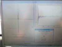
is this trace normal?

DSCF0900.jpg

i think it must be straigt up, not to the left ?!

anyone is familiar with it?
 
It's only straight up if it's aligned. What you need to do is pick the average line that best represents all of those dots. So something up and to the right a few degrees.
 
thanks!

i think its a very good alignment because when more to the right it will be curvy.
and the higher the rpm go when i record a trace, the more the points move to the right

so must it be allways in line from the bottom to the top?
 
It should be, yes. If it isn't, then you're not correctly aligned.

Try to run at a constant RPM as much as possible, 500-1000RPM maybe. I always used a drill to spin the motor.
 
ok with only up to 1000rpm the points are straigth up. only over 1000 rpms to 5000rpms the points move to the right.

ok thanks for the informations travis!
 
hi all,
recently i try to achieve the master/slave operation of the drives. But the following parameters i don't know how to configure it. I have set node 11 as master and node 33 as slave.
-how to setup the heartbeat consumer? The producer time is 250ms. Each time i set the value and run the software. It always occurs one of the problems, 'SDO timeout', 'No bootup' or'Heartbeat'.
-how to setup the SDO channels? In 0x1280 i have set 531 and 431 for node 33 and in 0x1201 i just set the default value 0x80000000.
But the problems are same as above.
-how to set the TPDO/RPDO? I have referred to the note Multi-Node-Setup written by Sevcon. And i just do as it said but another side of the wheel can not run. There muss be some problems with the configuration of the PDOs, but till now can't find any idea.
Hope the specialists here could give me some advices or someone who also deal with the Master/Slave problems can also send me the message and we could do it together.
Kind regards
Ming
 
Back
Top