
You are using an out of date browser. It may not display this or other websites correctly.
You should upgrade or use an alternative browser.
You should upgrade or use an alternative browser.
v-brake front fork mounting points?
- Thread starter Buk___
- Start date
Since they are all interchangeable (arms for Vbrake all fit all the Vbrake bosses), then yes.
But there are a number of bosses that look similar and are similarly--but not identically--placed, for other kinds of brake arms. See the Sheldon Brown site for info on the various systems. (best first place to go about basic bike-specific info)
So if you look at any Vbrake mounts you can use those dimensions to make your own, if that's your goal. If your goal is to use existing mounts and put them on your own fork, you could copy the placement of other forks' locations.
Or you can do what I did on my various bikes; I cut the brace off unusable "suspension" forks, and either welded or clamped them to better forks that didn't have Vbrake bosses. I added two sets to my SB Cruiser trike (cuz it has to stop a lot more mass, especially when hauling the trailer full of stuff, like ~600lb loads of dog food, etc).
(some threads about it, with pics; it all works better now than it did then)
https://endless-sphere.com/forums/viewtopic.php?f=2&t=67833&start=475#p1289564
https://endless-sphere.com/forums/viewtopic.php?f=2&t=67833&p=1324787&hilit=cruiser+brake%2A#p1324787
Some of the original mods to CrazyBike2 that led to the above:
https://endless-sphere.com/forums/viewtopic.php?f=2&t=67833&p=1289337&hilit=cruiser+brake%2A#p1289337
https://endless-sphere.com/forums/viewtopic.php?f=3&t=86230&p=1261632&hilit=cruiser+brake%2A#p1261632
I also added rear bosses to the Crazybike2 frame by cutting bosses off a scrap frame and welding them to the CB2 frame:
https://endless-sphere.com/forums/viewtopic.php?f=2&t=12500&p=955999&hilit=crazybike2+rear+brake%2A#p955999
some pics from a later post that show those added bosses
https://endless-sphere.com/forums/viewtopic.php?f=2&t=12500&p=1229244&hilit=cruiser+brake%2A#p1229244
Chalo
100 TW
Note that the ideal width between brake bosses is a function of rim width; if you're mounting bosses for a particular bike, take into account the rim you want to use, along with other prospective rims you might want to use at a later time.
Whatever boss spacing results in v-brake arms that are parallel to the plane of the wheel when fitted with thin pads and thin spacers is the right spacing.
Whatever boss spacing results in v-brake arms that are parallel to the plane of the wheel when fitted with thin pads and thin spacers is the right spacing.
amberwolf said:Since they are all interchangeable (arms for Vbrake all fit all the Vbrake bosses), then yes.
But there are a number of bosses that look similar and are similarly--but not identically--placed, for other kinds of brake arms. See the Sheldon Brown site for info on the various systems. (best first place to go about basic bike-specific info)
Thanks Amberwolf.
I did look at SB, Wikipedia and a bunch of other places, but as far as I saw, none of them give actual dimensions. The nearest I found was some numbers posted by someone in a google groups discussion which don't make a lot of sense to me.
(I did try searching the Shimano site for references, but none of my searches turned up anything. I mean literally nothing; which suggests their website isn't working right or my browsers aren't compatible, because I simply couldn't find any search term that would return any results at all.)
According to Shimano literature...There are two measurements....
First is the distance between the hub axle center and the brake boss
center.
The second is the height of the brake boss from the hub axle center.
For MTB frames using 26" (ISO 559) wheels: 253.5 +-1mm
For 700c (ISO622) wheels: 283mm +- 1mm, and between
For frames using 27" (ISO 630) wheels: 286 +-1mm
The "second dimension" for all is greater or equal to -8mm, and less than or equal to 70mm.
The written description of "First" and "second" leave a lot to the imagination, and there is no mention of a width. I guess as the only connection between the sides is the cable, and that is adjustable, whether the bosses are centered on the fork legs as I seen in some pictures or offset towards the wheel as on the set of forks I have isn't necessary to be fixed; and different rim widths can be accommodated by longer or shorter pad arms.
I've measured a set of dimensions from the set of forks I have; but if there was a known defined standard with tolerances, and preferably diagram(s), I'd rather use those than my own measurements of a single example, as the basis of design work. My notion is to use the redundant set of v-brake mounts on my forks (it has a a disk) to mount a friction drive; but it would be a single unit that mounted to both mounts and if it was ever to be transferable to a different set of forks, I'd need to design in some way to accommodate different widths.
It's all just ideas in my head and lines on a computer screen at this stage, but if anyone knew of a definitive standard, it would be a nicer starting point than my one-off set of measurements.
dogman dan
1 PW
I would guess that height above the rim for the boss could be measured right off the particular v brake you plan to use. Or just copy a fork, or rear stay measurement. Distance from center of axle to the center of the boss, for that wheel size.
Then like Chalo said depending on the wheel you plan to use, mount so the v brake is not set cocked tilting in, or out, to reach the rim. Make them pretty much straight up and down, when the brakes are touching the rim. this is tilted out some on the top when the brakes are off, but not a lot.
For side pull brakes, I have found you really need to have the brakes in hand, before you weld on the piece you plan to bolt them to. Lots of differences, particularly modern vs vintage.
dogman dan said:I would guess that height above the rim for the boss could be measured right off the particular v brake you plan to use. Or just copy a fork, or rear stay measurement. Distance from center of axle to the center of the boss, for that wheel size.
Then like Chalo said depending on the wheel you plan to use ...
Yeah. I was hoping there was enough of a standard defined that I could design my unit flexibly enough that it would be transferable to other forks/bikes.
For that, I'd need to know defined ranges and tolerances. Maybe that does not exist; but I hoped by asking here I might find out.
I've discovered that there are at least two front axle widths: 100mm and 120mm. But that doesn't really define anything because the dropout plates can be attached inboard or in the middle, (or presumable outboard, though I haven't seen an example of that), and anywhere in-between; there are many diameters of stanchion/leg, and many are not round; and the attachment point of the pivots can apparently be in the middle of the stanchion, inset, outset or in the case of bolt-on adapters, completely inboard of the stanchion edge. A totally fluid target.
Hence, my search for a 'standard' if it existed; which its looking more and more like it doesn't.
Not sure if replying to oneself is the done thing here, but I found some further info that whilst not definitive at least seems consistent and reasonably authoritative here, which I'll post in case the title draws anyone else to this thread.
From: "goodrichbikes"
Subject: Re: Frame Canti Boss Location - Std Dimensions Available?
Date: Mon, 20 Dec 2004 13:29:51 -0600
700C(622) = 283mm
26"(559) = 253.5mm
650B(584) = 265mm
A post center to post center measurement of 80mm works best for most canti & v brakes.
Curt Goodrich
Minneapolis, MN
Date: Wed, 26 Jan 2000 01:00:11 -0500 (EST)
From: Jeff DelPapa
Subject: Frame measurements question
The last time I asked about canti spacing, the number I got was 80mm center to center, apparently from the literature of the big S. I expect it should depend on the rim width, but they didn't mention a correction. As to distance from axle, I was told 25mm less than the bead seat diameter, which worked fine for the canti's I used. (happened to be scott self energizing -- pre linear pull style.)
Subject: Re: Frame Brake Boss Location
From: "Jon_norstog AKA \"Thursday\""
Date: Fri, 14 Oct 2005 20:03:56 -0600
I'm working from the 1999 Shimano book. The spacing between canti posts depends a little on rim width. basically it's 77-85 mm, but on a road bike you could probably go down to 75 and be fine..
I use 80 for mountain bikes and 85 for BMXers and bikes that are gonna run V-brakes and wide rims.
I don't recall finding any either, which is why I recommended measuring something you have access to.Buk___ said:I did look at SB, Wikipedia and a bunch of other places, but as far as I saw, none of them give actual dimensions.
")
(I did try searching the Shimano site for references, but none of my searches turned up anything. I mean literally nothing; which suggests their website isn't working right or my browsers aren't compatible, because I simply couldn't find any search term that would return any results at all.)
Probably their site uses scripts / java / flash (or some other graphical method) to serve up the content in a non-text format, so there is nothing for a search engine to find. The internet seems to be waffling back and forth between that kind of page and more text-oriented pages over the years.
Ah. For that, you'll need something that not only has adjustable width "legs" to mount on, for different widths of fork (and tire), but also an adjustable height to clear various size tires.My notion is to use the redundant set of v-brake mounts on my forks (it has a a disk) to mount a friction drive; but it would be a single unit that mounted to both mounts and if it was ever to be transferable to a different set of forks, I'd need to design in some way to accommodate different widths.
Another thing to consider is narrow mounts but fat tires, so the "legs" would need to be angled or C-shaped to reach around the tire.
dogman dan
1 PW
Well, any fork you measure would fit any bike with compatible headset, and be suitable for typical rim widths on that type of bike.
So uhh,,, like AW said, go down to the store and measure some shit. Looks like you found the length anyway, I mean measure width, on bikes with fat and skinny rims.
Obviously, width will be different for different rims, vs a regular bike 100 mm axle, and rims around 25-30 mm. If you want fat, or even just medium fat, then you will have a wider rim than 30mm and everything will be different.
Anything you build or modify will fit any bike of that type, but of course there will be no standard width for every bike. Go measure a bike of the type you plan to build.
Or like I said, get yer rim, fork or swing arm, and brakes in hand. Then look at what it takes to make the damn thing square up with that rim, when the brakes are on. This is how you make custom shit fit, you fit it once you have the parts in hand.
dogman dan said:This is how you make custom shit fit, you fit it once you have the parts in hand.
The whole idea was to avoid having to hand fit custom shit.
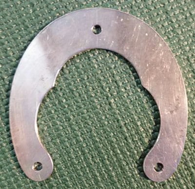
I suppose you could go with a median-fit and use a bracket like the stiffening-U braces (brake booster, booster arch, etc) for brakes; they typically have slots (rather than round holes) for the screws to go thru them and into the bosses.
\
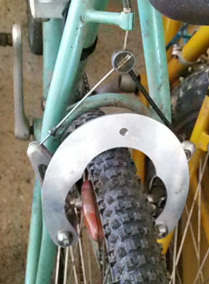
This image shows the arch I have installed on the front-front brake of SB Cruiser, with the bolts on the inner end of the slots; the arch could be used on a wider fork (or wider boss placement on a narrow fork), perhaps another 10-20mm wider than mine. It doesn't have enough vertical clearance for really big tires, though, so to get that you'd need something more like the Ohm symbol (omega) than a U.

This post by Chalo
https://endless-sphere.com/forums/viewtopic.php?f=2&t=67833&p=1289575&hilit=brake+booster#p1289575
shows a really beefy brake setup, but the idea is you could make your mounts like the front arch in that pic, or some variation of it.

This post by Chalo shows an easy way to make your own arch, with just a hole saw to cut the arch out in 3 cuts.
https://endless-sphere.com/forums/viewtopic.php?f=2&t=67833&p=1289251&hilit=brake+booster#p1289251
\
This image shows the arch I have installed on the front-front brake of SB Cruiser, with the bolts on the inner end of the slots; the arch could be used on a wider fork (or wider boss placement on a narrow fork), perhaps another 10-20mm wider than mine. It doesn't have enough vertical clearance for really big tires, though, so to get that you'd need something more like the Ohm symbol (omega) than a U.
This post by Chalo
https://endless-sphere.com/forums/viewtopic.php?f=2&t=67833&p=1289575&hilit=brake+booster#p1289575
shows a really beefy brake setup, but the idea is you could make your mounts like the front arch in that pic, or some variation of it.
This post by Chalo shows an easy way to make your own arch, with just a hole saw to cut the arch out in 3 cuts.
https://endless-sphere.com/forums/viewtopic.php?f=2&t=67833&p=1289251&hilit=brake+booster#p1289251
amberwolf said:I suppose you could go with a median-fit and use a bracket like the stiffening-U braces (brake booster, booster arch, etc) for brakes; they typically have slots (rather than round holes) for the screws to go thru them and into the bosses.
\
This image shows the arch I have installed on the front-front brake of SB Cruiser, with the bolts on the inner end of the slots; the arch could be used on a wider fork (or wider boss placement on a narrow fork), perhaps another 10-20mm wider than mine. It doesn't have enough vertical clearance for really big tires, though, so to get that you'd need something more like the Ohm symbol (omega) than a U.
Thanks amberwolf, especially for digging out the pics and threads; real food for thought there.
The (very) basic idea is something like this:

(Those motors aren't a final choice, just a possibility -- right kV and power -- but mostly a good diagram available for them.)
There are three problems to address;
- Accommodating different widths of pivot to pivot point.
- Height adjustment of the motor(mounts) relative to the pivots.
- Reach adjustment of the motor(mounts) relative to the pivots.
And that's further complicated by the desire to have the motor mount pivot in the same axis as, but offset forward from, the motors rotational axis. The idea is that they are manually engaged to the rim via the cable, but once the motors are running at the same speed as the rim, they will over-center, and lock against the rim until the power is cut or the brakes are applied.
Now I have some "standard" dimensions, it gives me an idea of the size and scope of variations that would need to be accommodated to come up with a widely reusable unit. Probably impossible to design a single unit to handle everything, and probably a waste of effort to try, but any boundaries I can define up front can't harm.
If you're going to use the brake bosses as pivot points (or have other pivots along the same axis), you have to use smaller diameter motors and in place of the brake arms, or else it won't be on the rim, it'll be on the tire at an angle to the wheel some distance from the fork.
Try it out with some lids off of juice bottles (about hte size of the motors you've shown), and see what I mean. They just can't line up with the curving rim.
You could put them *behind* the fork, parallel to the brakes, but unless the motors are smaller diameter they'll be "inside" the fork in order to be at the right angle while in-line with the brake boss pivot axis.
You'd have to "bend" the axis downward significantly more the farther away from the fork the motor gets (larger motor diameter) to keep the side of the motor parallel to the rim.
Something else to think about is the narrower the motor is, the less torque it will produce for the same conditions otherwise, and more losses it will have (more end turn copper in proportion to the less in-stator copper). Similarly, the smaller the diameter, the less torque.
amberwolf said:If you're going to use the brake bosses as pivot points (or have other pivots along the same axis), you have to use smaller diameter motors and in place of the brake arms, or else it won't be on the rim, it'll be on the tire at an angle to the wheel some distance from the fork.
Hard to show without moving to 3D, but whilst the clamping action rotates the motors around the pivot point axis, the motor's rotational axis is forward of the end of the pivot boss, and rotated forward relative to the fork. Something like this:

dogman dan
1 PW
IMO, hand fitting shit is what custom is all about. If you plan to use stock stuff, same typical rim width as mtb's and cruisers, then of course no need to hand fit anything, just make it same as you measure down at Walmart.
dogman dan said:IMO, hand fitting shit is what custom is all about. If you plan to use stock stuff, same typical rim width as mtb's and cruisers, then of course no need to hand fit anything, just make it same as you measure down at Walmart.
I don't plan to "use stock stuff", so much as design something that has the potential to become stock stuff. Ie. Whilst I'm designing for me; if I cock an eye to the possibility that I(or someone else) might want to use the design on a different bike in the future, then knowing the probable limits to which it might need to adapt just makes it easier to design that adaptability in.
Similar threads
- Replies
- 6
- Views
- 359
- Replies
- 8
- Views
- 218
- Replies
- 0
- Views
- 401
- Replies
- 5
- Views
- 439