
Build your own caps shaped the way you want? ")
Arlo1 said:Now to let everyone know.. HH is very doubtful this will work well. He let me know I am breaking all the design rules. But I know I am breaking the laminated buss design rule and my hope is because they are in side the middle it won't be such a big deal.
Lebowski said:Arlo1 said:Now to let everyone know.. HH is very doubtful this will work well. He let me know I am breaking all the design rules. But I know I am breaking the laminated buss design rule and my hope is because they are in side the middle it won't be such a big deal.
I am with HH on this one... I think a lot of attention should be paid to how the currents flow and how they change throughout the full switching cycles. Throughout the switching cycle the current should (as much as possible) stay in the same 3D space, minimizing current and voltage spikes and associated extra switching losses.
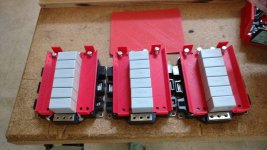
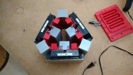
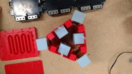
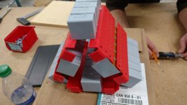
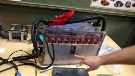
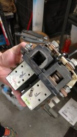

I think it will be quite awesome. Because each + and - will have 3 paths from top to bottom and a parallel link on each the top and bottom cutting inductance into 1/3 But I am well aware it should have laminated DC buss... EACH IGBT is laminated inside but the power buss I designed under the caps is not. I know this is a risky move but so far the CRX has worked without any laminated buss what so ever!marcos said:That array of snubber-like dc link could have a tenth of the parasitic inductance if you could use a laminated bus bar.
The question is if that monster cares at all about a few nH of inductance. Depends on your rise times, I guess you have heatsinking room to switch it slower.
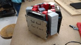
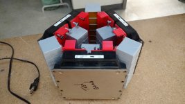
Its looking good!