Stevil_Knevil
10 kW
Yay math!
Geeks rule.
Geeks rule.
bataanjr said:To vent a hub engine is not making holes and nothing is the way or rather the angle look at this.
https://sites.google.com/site/shelbyelectro/motors/mods/ventilating-a-hub-motor
windtrader said:It does seem like a pretty simple and light finned rotor could be cast and attached to the side of the housing. Holes matching the fin placement could then be cut into the housing and thereby created a forced air flow into the hub. Exhaust could be simply some holes on the other side, maybe put in places to facilitate minimize restriction or maybe over areas that could use some more flow on that side. It's just a more manufactured way to do what has already been custom fit.
Allex said:What about car windows. When you open it(even half ways) you get a lot of air inside even tho it is flat. And when you open another window on the other side you have even more. Does it work because the opening is much bigger compared to the drilled hole in the motor?
windtrader said:OK. back to old school the scooped ram air style but no cooling when not moving. Plus if grinding up steep hill, probably not enough speed to get enough flow while motor is cranking big amps. couldn't a fan be installed in an induction tube to drive air as required at all speeds and times?
John in CR said:bataanjr said:To vent a hub engine is not making holes and nothing is the way or rather the angle look at this.
https://sites.google.com/site/shelbyelectro/motors/mods/ventilating-a-hub-motor
Too old. Venting like that has been proven to create little flow. How many fans have you ever seen that consist of holes in a spinning flat plate?....None. I was one of those big into the hole shapes and angles of cut, because I had success, but it turned out that it was my blades on the interior of the covers that made the air spin enough to get centrifugal flow worth mentioning.
Then when I had motor with no room for interior blades, I had to put my hand almost touching the exhaust holes to feel the flow. Air can't carry much heat, so you need a lot of flow to move much heat, so I added just 6 exterior centrifugal fan blades that extend 1" beyond the perimeter of the motor sheet. Now I get tremendous flow with intake on one side and exhaust on the other with holes and slots small enough that nothing larger than 2mm can even enter the motor.
bataanjr said:It will be old nor ideal but better than direct holes that's what most people.

teslanv said:Math and physics are fiction? That's news to me.
ohzee said:+1 for the smiley face.
Sounds interesting just not sure if id want to deal with a radiator and tubes.
You'd need to run that to the front of the bike to get idea airflow would you not ?
Still while my needs are pretty simple I find it very interesting.
kiwifiat said:You can play around with controller settings and wheel diameters until you go blue in the face but the one thing that remains true is that for the same current and the same diameter wheel the higher torque constant motor with generate the highest tractive force.
The takeaway from all of this is that if you ride around a hilly terrain you are better off with a higher turn count motor.

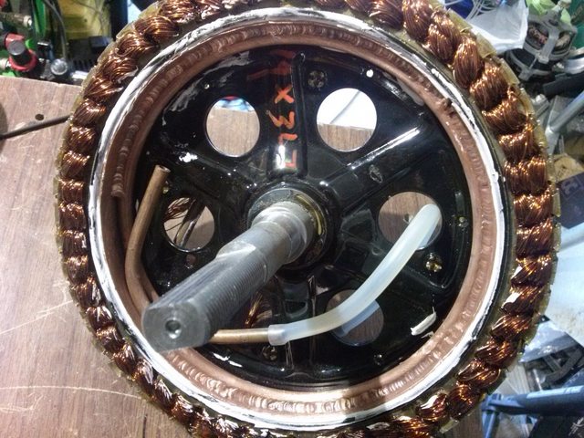
Allex said:John if I understand your text correctly we need to do something like this to "create a significant low pressure behind the blade, so air flows out of exhaust holes immediately behind the blades quite strongly, which is replaced by fresh air flowing into the intake".
View attachment 3
The only problem would be Rear caliper in the way, so probably something like this if you want to fit a brake there?


kiwifiat said:teslanv said:Math and physics are fiction? That's news to me.
There are no myths in science or maths just plenty of opportunity for misinterpretation and errors.
Lets agree that the torque constant for two electric motors that differ only in the number of turns will be higher for the motor with the highest turns. This is only a myth if the Lorentz force equation is false, which it simply is not and it can be easily verified with a strain gauge, a magnet, a length of wire and a variable current source.
So can we all agree that if you drive both motors with the same amps then the motor with the highest turn count will produce the highest torque. And it follows that in the same diameter wheel, the higher turn count motor will produce the higher tractive force at the ground since F = T/r. No myths here just irrefutable verifiable facts.
You can argue that you can push more amps into the lower turn count motor so that it produces the same torque as the higher turn count motor did at a lower current and that is quite true. It is also true that if you push the same higher current into the higher turn count motor you get more torque than the lower turn count motor. The torque constant is not a myth. You can play around with controller settings and wheel diameters until you go blue in the face but the one thing that remains true is that for the same current and the same diameter wheel the higher torque constant motor with generate the highest tractive force.
The takeaway from all of this is that if you ride around a hilly terrain you are better off with a higher turn count motor. You can be sure that the Kv of an electric motor has nothing to do with the size wheel you put it into and equally Kt has nothing to do with the size of the wheel you put it into.
Merlin said:I like those technical Battles of "iam and you are not"
My solution about efficiency?
If my Battery is empty, i'll charge it.
If i need more Juice for better Range, Update your Battery Capacity