Compact Field Oriented Controller, ASI + Grin, limited run

I am message number 1000 on this thread!!!!!! :D :D :p :p

Well, what I wanted to ask is about the upper voltage cut.
I am running a system of 3.3*25 = 82.5V 20Ah A123 prismatic cells. (3.6V@cell fully charged for a total of 90V, but I do not charge them more than 3.5V@cell)
The highest upper voltage cut on the Phaserunner is 90V. It seems that if the pack has not been discharged enough, the regen can cause the voltage (as seen by the Phaserunner when including resistance drops) to rise a bit above 90V.
When it does, it causes a high-voltage fault where you need to clear it or restart the controller.
This brings two questions:
1. I thought the regen-voltage was supposed to roll-off as you approach the highest voltage limit and not overshoot.
2. Is there a way to make the controller just show a warning and temporary shut-off/roll-off the regen, just like the Grinfineon does, instead of entering fault mode? This is very dangerous when you rely on regen during a steep downhill. (along with the mechanical brakes of course)
 
thunderstorm80 said:
1. I thought the regen-voltage was supposed to roll-off as you approach the highest voltage limit and not overshoot.
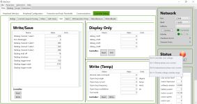
What are your settings for Max Regen Voltage (Start) and Max Regen Voltage (End)? Setting these appropriately works fine for me, although I'm not as close to the absolute limit as you are.
 
Justin
Anything else done on the generic chinese sines vs trap?

https://endless-sphere.com/forums/viewtopic.php?f=31&t=65031&p=1197760&hilit=FOC+more+torque#p1197760
 
I think I might be looking at the next motor controller for my bat-mobile trike :) Thanks to Alan B. for point it out to me...

So, has anyone tried this with a Cyclone 3000W motor already?

G.
 
thunderstorm80 said:
I am message number 1000 on this thread!!!!!! :D :D :p :p

Well, what I wanted to ask is about the upper voltage cut.
I am running a system of 3.3*25 = 82.5V 20Ah A123 prismatic cells. (3.6V@cell fully charged for a total of 90V, but I do not charge them more than 3.5V@cell)
The highest upper voltage cut on the Phaserunner is 90V. It seems that if the pack has not been discharged enough, the regen can cause the voltage (as seen by the Phaserunner when including resistance drops) to rise a bit above 90V.
When it does, it causes a high-voltage fault where you need to clear it or restart the controller.
This brings two questions:
1. I thought the regen-voltage was supposed to roll-off as you approach the highest voltage limit and not overshoot.
2. Is there a way to make the controller just show a warning and temporary shut-off/roll-off the regen, just like the Grinfineon does, instead of entering fault mode? This is very dangerous when you rely on regen during a steep downhill. (along with the mechanical brakes of course)

Me too. I've just connected my 22S lithium battery and had the issue with the voltage. I discharged it to 89.5v and now i'm trying to set up the Regen. It's not working for the same reason. I'm getting the over voltage error. However, if I switch to a 36v battery, the Regen works. Can anyone confirm if Regen braking should work with high voltage batteries?

At 36v, the Regen is not variable it seems. Does anyone know how to make it variable?

I'm using a half-twist throttle for both Regen and Throttle and even though it's the same product, i get a different voltage ranges in the dashboard. It's 0.8v to 4.2v for the throttle and 1.8v to 4.2v for the Regen brake. Anyone know why that might be?

I've found that my throttle setting do not work until I add 0.4v Deadband, regardless of the range i set.

My Autotune worked at battery voltage of 89.5, but with the rated battery voltage set to 48v. I get errors when i change the setting.

There is no connection between the Max Wats setting and the battery currents. I find this really confusing. Could it not reflect changes as all the other parameters do? Does the Max Watts not rely on the voltage reading, or does it vary the amp limit based on the voltage reading to always ensure the Max Watts limit is met?

I was also wondering if a chunky bike frame is enough of a heatsink to start hitting 70Amps Phase current.

Thanks for all the information people, I do love this product. Wish i could get the Regen working and i'm done!

IMG_3956 (3).jpg
 
markz said:
Justin
Anything else done on the generic chinese sines vs trap?
https://endless-sphere.com/forums/viewtopic.php?f=31&t=65031&p=1197760&hilit=FOC+more+torque#p1197760

Yes! :) And No :-(

I've done a number of dyno tests of given motors with sinewave controllers and also with the phaserunner, but not yet in a way that is directly comparable where the input powers in both cases were limited in exactly the same manner, with the same motor on the bench etc. so that we can super-impose the data in a fair way. At issue in part is that the chinese sinewave controllers I've had to test tend to be poorly behaved as they approach the unloaded motor RPM, it seems that they are doing overmodulation to achieve the same rpm's as a trap controller but in a way that is prone to oscillations and sudden changes in torque. Rather than a nice ramp in torque and power vs. rpm the data is kinda messy.
 
John Bozi said:
my 2 cents
This looks worse that the last model. It looks pregnant with connections and I had mine on my handle bars for maximum air flow. With that added stuff there it will be bulkier where ever you put it. With cables you got more chances to hide connections somewhere else.

Hey John, I would in fact mostly agree with you here and appreciate your frankness. This was my biggest reservation about fully connectorizing the assembly at the controller end, and if we had a way to scale up the manufacturing while leaving the full power cables coming out of the potted housing then we totally would have. To give some perspective, in the previous cabled design with someone working full time at Grin doing nothing but phaserunner assembly, we were only able to average all things considered about 2 units per day. Hopefully now it will be more like 4-6!

Anyways there are some perks and flexibility advantages to the connectorized power cable harnesses, but it won't be as neat looking as just a cable coming out. A velcro sleeve or similar can hide the plugs but the aesthetic won't ever be as slim.

The only thing that failed my on my phase runner all axle plug and play purchase was the Anderson connectors running high phase amps, something I didn't think was possible

Yeah the Anderson was a poor choice for the phase wire connector standard as above about 70A continuous they can melt, and the Phaserunner makes it easy for people to push this level of phase current in their motors. The MT60's are a lot more rugged in this regard, and we wouldn't have proceeded with them for a potted phase connector if there was any doubt.
 
davideserin said:
Me too. I've just connected my 22S lithium battery

Hey everyone, 21S is really the maximum voltage pack that you should use with the Phaserunner controller, at 22s you are over the voltage limits with a charged pack. We only anticipated it for 20S setups although with 21s at full charge things are still OK and you can do regen right to the end. The maximum you can set the overvoltage fault setting to is 89.9 volts (this setting is on the advanced tab, don't confuse it with the regen voltage), and the max regen voltage should be at least 0.5 to 1V lower than this so that you don't have any transients causing the overvoltage fault which requires the controller to shut off. So your max regen voltage start is at about 88.5V, which is way too low for a 22s battery (ie 92.4V fully charged).

davideserin is there a specific reason to be running 22S rather than the much more common 20S standard? If you can configure a 20S pack instead I'd recommend doing that for sure.

Also, please just leave the rated system voltage alone (at 48V) after you've done the autotune etc. it says so clearly in the manual and on the tooltips, there are lots of dependencies with other parameters that get affected and then clamped when you change this setting after the fact.

At 36v, the Regen is not variable it seems. Does anyone know how to make it variable?

It is completely variable, the regen phase current will vary linearly from 0 amps to the max regen amps as the regen signal (blue wire) goes from the brake off voltage to the max braking effort voltage. In your case you'll be swapping the default slope for the regen map so that it max regen amps setting his at a higher voltage than the start.

I'm using a half-twist throttle for both Regen and Throttle and even though it's the same product, i get a different voltage ranges in the dashboard. It's 0.8v to 4.2v for the throttle and 1.8v to 4.2v for the Regen brake. Anyone know why that might be?

The ebrake signal has an internal pull up resistor while the throttle has an internal pull down, such that when they are shorted the signal sits at 1V so that by default with nothing plugged in there will be no throttle or braking. If you are using a normal throttle for the ebrake, then I'd recommend putting like a 10K resistor between the signal and Gnd so that it also has a normal voltage range. Hall effect throttles are sortof like open collector devices, they can't actively pull a signal down, only lift it up.
 
justin_le said:
Hall effect throttles are sortof like open collector devices, they can't actively pull a signal down, only lift it up.

Assuming an NPN transistor, then open-collector does actively pull a signal down to ground. ;)

A PNP could pull up, though.

Only mentioned because NPN is the most common OC type, including that on switching (not linear-out) halls, like those in motor sensors and on/off ebrake lines.

But I understand where you're going with the analogy. :)


Regarding the Andersons--it's just the small PP45s that are the problem, as they're not designed to carry that much current. Going up to the PP75's or higher (or SB series, which use the same contacts) would solve that issue, as long as a version is chosen for the max phase current of that system.

Unfortunately the PP75s are each almost the size of an average pinky finger....
 
Hi Justin, thanks for the advice. I also saw the updated manual now.

davideserin is there a specific reason to be running 22S rather than the much more common 20S standard? If you can configure a 20S pack instead I'd recommend doing that for sure.

I was just trying to get the most speed from the system, but I'll just change it to a 20S as i really want the Regen function. Would be good to clarify that in the manual and website as you mention 22S working, which i took at face value.

The ebrake signal has an internal pull up resistor while the throttle has an internal pull down, such that when they are shorted the signal sits at 1V so that by default with nothing plugged in there will be no throttle or braking. If you are using a normal throttle for the ebrake, then I'd recommend putting like a 10K resistor between the signal and Gnd so that it also has a normal voltage range. Hall effect throttles are sortof like open collector devices, they can't actively pull a signal down, only lift it up.

OK, great, i'll try that out. I'm keen to also use the brake levers to get proportional regen braking. Is that possible with the Tripwire? I'm guessing not as it's only two wires. Do you have a product that can do that, or should i just make my own hall sensor setup?

If anyone knows of a good guide for the latter, let me know please! :)

Thanks!
 
davideserin said:
I'm keen to also use the brake levers to get proportional regen braking. Is that possible with the Tripwire? I'm guessing not as it's only two wires. Do you have a product that can do that, or should i just make my own hall sensor setup?
I haven't seen a commercial lever with variable output - the e-brake levers you see are either on/off halls or make/break switches. You can use something like that if you only want fixed regen. I've used a thumb throttle for variable regen.

Here's a cool idea - using a hydraulic lever and adding a pressure transducer to the cylinder:
Moped left level master cylinder, drilled and tapped for a 300psi Hydraulic pressure transducer which is used as the analogue regen input on the Mobipus controller. Feels like having a gigantic super powerful rear brake, very intuitive to use. No physical brakes on rear anymore.
 
cycborg said:
Here's a cool idea - using a hydraulic lever and adding a pressure transducer to the cylinder:
Moped left level master cylinder, drilled and tapped for a 300psi Hydraulic pressure transducer which is used as the analogue regen input on the Mobipus controller. Feels like having a gigantic super powerful rear brake, very intuitive to use. No physical brakes on rear anymore.

That would be the ultimate wouldn't it. It would really give proper feedback of the level of force applied. I've asked for more details, so let's see.
 
Mech-brake guys could switch in a dual pull lever and run the second cable to a cable-pull hall throttle. Member gwhy! used to sell such a throttle, but I think he stopped. There are equivalent units available for about $25. This lever by Fixcraft has the same long pull on both cables, but the over/under style from other manufacturers would be okay too since you can tweak in the regen voltage range regardless of the motion range. Or just use a standard single cable lever if you only want regen braking...

View attachment 1cablePullHallThrottle2.png
https://shop.fixcraft.net/bike-components/lifeline-star-dual-long-pull-lever#.WdQimzUpDmE
https://www.electricscooterparts.com/throttlesstandard.html
https://endless-sphere.com/forums/viewtopic.php?f=31&t=58801#p877794
 
so... 6 months ago my phaserunner failed. I was riding home from work, about 6 of 8 miles in, and boom... cuts out. I power cycled, checked the connections, etc but no luck. pedaled the last 1.7 miles home.
since then the bike has just sat... until today.

today I took a vacation day for myself, and since I had finally found the controller cable, I decided to fix my ebike.
since I now have a new laptop I tried the latest greatest Grin software first. connected first try, the interface was a little too tall to fit on the screen, but I managed to resize it.

with the software connected I could immediately see some faults.
Code:
Faults[0]: Controller over voltage
Faults[1]: Filtered phase over current
Faults[9]: Instantaneous phase over current
Faults[11]: Throttle voltage outside range
Warnings[7]: VdcLowFLDBK
Warnings[8]: VdcHighFLDBK
Warnings[12]: HiSOCFLDBK

hmm. so I hit clear. they dont go away.
So I unplug the motor. try to clear. No change.
I use the dashboard. but I cant see anything changing when I move the throttle.

I decide that since im unfimliar with this software, I will load BACDoor.
error.png

The errors dont clear. I disconnect the CA-v3 from it. no change. I disconect EVERYTHING from it. nothing connected to the Phaserunner except the power. They still dont clear.

Looking closely at the errors, the one that bothers me the most is throttle overvoltage. everything reads as 105% throttle, or just OVER 5v... but with the CA it should be dead on... I check the CA output with a extra connector and a voltmeter, and its spot on. not the problem. I check the 5v bus via the throttle connector. its 4.98v by my meter (not a perfect meter). hmm.

so heres my worry. I think my phaserunner is fried. I mean, I dont know how the thing is "overvoltage". I dont know how the throttle is pinned past 5v. I dont know everything is overcurrent when nothing is connected... unless.... one of the MOSFETs is fried and feeding pack voltage into the mosfet gate pin. ugh.


So before I throw it aside and order a new controller... any ideas?
 
MrDude_1 said:
So before I throw it aside and order a new controller... any ideas?

Hey MrDude, can you follow the steps outlined in this post here to do a full reset of all the many parameters to factory defaults?
https://endless-sphere.com/forums/viewtopic.php?p=1310696#p1310696

In cases where there has been a corruption of the memory settings resulting in all kinds of error messages like you had this usually sorts it.
 
justin_le said:
MrDude_1 said:
So before I throw it aside and order a new controller... any ideas?

Hey MrDude, can you follow the steps outlined in this post here to do a full reset of all the many parameters to factory defaults?
https://endless-sphere.com/forums/viewtopic.php?p=1310696#p1310696

In cases where there has been a corruption of the memory settings resulting in all kinds of error messages like you had this usually sorts it.

Just tried that.
with nothing connected to it except power and the comm cable, it shows the same errors.
I checked the box, hit save, then imported the xml file, checked that the box was still checked and hit save. it said "success" but no faults cleared. I then tried to clear the faults, it says success, but the faults remain.
I tried several times with the box clicked incase the order mattered..
no change.

is there any other file or flash I can try?
I worry that I killed it.
I ran it maxxed out, with a big heatsink.
I have a 3T X5, a motor known for eating amps.
I have a nice huge 20+ah 16s pack.
I run it flat out at around 42mph for most of my commute.

I worry that since the motor will continue to sink max current, the current is limited by the phaserunner...
the phaserunner will normally roll back power based on heat, but I have a huge heatsink... so it never gets hot.
so I worry that im just pulling way too much power through it, and fried it.
 
Generally if all sensor readings drift by some offset in some direction, it means the Vref (Voltage Reference) changed/drifted.

Your use model keeping it to cool on a giant heatsink and feeding a hungry motor sounds like winning at ebikes. :)
 
My motor seems to keep going at low amp after applying the throttle. Once it spins up and i release the throttle i still see around 60W going in. I am controlling it with a CA and it shows throttle out voltage as 1.0. The minimum throttle i have on the controller is 1.10. I dont understand why my motor keeps spinning.
 
madnut said:
My motor seems to keep going at low amp after applying the throttle. Once it spins up and i release the throttle i still see around 60W going in. I am controlling it with a CA and it shows throttle out voltage as 1.0. The minimum throttle i have on the controller is 1.10. I dont understand why my motor keeps spinning.

Open the software, go to the dash-board, and observe the actual voltages.
In some cases, the actual voltage measured on the Phaserunner is not the same like on the CA, due to calibration errors.
 
justin_le said:
You don't really need to worry about overcharging the lower voltage battery from regen, it takes a pretty contrived situation for that to be an issue and you can always tell from the voltage and accumulated Ah on the CA if you are above the full charge voltage and then just stop doing regen. But in any normal situation, you'll be consuming way more amp-hours than you are regenerating and the risk of accidental battery overcharge from regen is basically nill, unless you live at the top of a very large hill and start off with a full charge on the pack.

What can I do to prevent damage but still have some regeneration?
 
rberger said:
What can I do to prevent damage but still have some regeneration?

Easy, just set your charger to only charge to like 90 or 95% and then you'll always have plenty of room for regen energy even at the start of a trip. Otherwise I would set the Phaserunner's max regen foldback voltage to 4.25 V/cell, which will even let you do a bit of regen when the pack is otherwise 100% charged. An occasional short excursion for the cells from 4.2 to 4.25V isn't going to have much consequence.
 
justin_le said:
rberger said:
What can I do to prevent damage but still have some regeneration?

Easy, just set your charger to only charge to like 90 or 95% and then you'll always have plenty of room for regen energy even at the start of a trip. Otherwise I would set the Phaserunner's max regen foldback voltage to 4.25 V/cell, which will even let you do a bit of regen when the pack is otherwise 100% charged. An occasional short excursion for the cells from 4.2 to 4.25V isn't going to have much consequence.

Hi Robert, I generally agree with the advice Justin has given you.

But, on my bikes I have set the regen start foldback to 4.01v/cell and regen end foldback to 4.11v/cell. I tried higher voltages (as little as 0.03v/cell higher) and those settings would occasionally allow voltage spikes sufficiently high to exceed the controller overvoltage threshold (about 4.3v/cell) during regen.

When an overvoltage threshold is exceeded the controller throws an error that can only be cleared on the road by cycling the power. On my bikes this occurred with a fully-charged battery when spinning up an unloaded motor when the over voltage threshold was set too low, or while applying regenerative braking on a descent as you might do when riding into town from your house. In the second situation regen braking would suddenly (and alarmingly) release as the controller went into error mode.

Unless you plan to start your ride by heading uphill I recommend you start by charging your battery no higher than about 1.5Ah from full if you expect to enjoy full regenerative braking on your 300m descent into town. (I get about 1Ah of regeneration per 300m of descending.) You may need to experiment over multiple trials by adjusting your maximum charge until you notice slightly reduced regen braking effectiveness as the controller rolls back regen near the bottom of your descent.

The alternative is to rely more on your friction brakes that I hope you have not removed from your bike.
 
If anyone here is capable of and willing to do a post mortem on my dead phaserunner so we can tell why it failed, I would be willing to ship it. Im kind of curious.
 
As i’m still learning about advanced controlers, the BAC800 and phaserunner. Can anyone help sort and compare the function of each? Advantage Grin?

Thanks,

T

Grin responded with a link to here but I don’t find a direct comparison.
 
Back
Top