KT motor controllers -- Flexible OpenSource firmware for BMSBattery S/Kunteng KT motor controllers (0.25kW up to 5kW)

casainho said:
@geofft: nice that you got the training bike roller, would be great if you could put a constant speed and adjust the value for FOC_READ_ID_CURRENT_ANGLE_ADJUST. Can you please share with us how was the process and the final value for your motor?

I've tried this with an old-fashioned crt 'scope :-

FOC angle scope trace.jpg

..this gave a 'rough' result for my (Q128H) motor of about 150 degrees. I've treated myself to a DS212 DSO however, should be able to give a better figure when that arrives... :wink:
 
stancecoke said:
honya96 said:
@stancecoke - I am getting an error

I've fixed it, just a few minutes ago :wink:
Please download the branch again!

regards
stancecoke

measured 1,564v for cal B(before, the high value was the second controller), so I have set -320

after flashing the fw, motor started to run itself and power on lcd jumping between 40-1999w

how to set correct cal A?
 
@ stancecoke, can you send me the link to how to set values in osec config tool? I can translate to english and explain for beginners :wink: (like me) later you can add them to the tool.

edit: so there is not that much to explain, and google translates it well. + automatic calculations can be added to tool, so maybe its not worth redoing now
 
tried unplugging throttle, so its not wrong throttle min value.

First thing I noticed is better than on main branch, turning off lcd while running motor is ok. with main branch it stops the motor fast.
 
honya96 said:
measured 1,564v for cal B(before, the high value was the second controller), so I have set -320
after flashing the fw, motor started to run itself and power on lcd jumping between 40-1999w
how to set correct cal A?

Ah, a good sign!
First you have to decrease the cal b step by step until the motor isn't running at startup, values from -310 to -312 are usual. If you found the right value, please make some measurements with Battery Current max set to

First: 10-Battery Current cal b (example for Battery Current cal b =-318: 10-(-318) = 328)
Second: 20-Battery Current cal b
Third: 30-Battery Current cal b

leaving the Battery Current cal a value at the default value of 10

Then run the motor with full throttle and look at the current it's drawing and post the values of Battery Current max and the found current. Than we can calculate the right value for Battery Current cal a

Edit: You will have to put load on the wheel, to get the full current...

The german wiki can be found here:
https://www.pedelecforum.de/wiki/doku.php?id=elektrotechnik:eek:pen_source_firmware_java_tool

The new parameters are not described, yet, but I think, they are self-explaining.

regards
stancecoke
 
328 gives about 1,75A. sometimes the motor does not start slowly by throttle, but there is a delay and then hard pull. :shock:
338 gives 2,7-3,0
348 about 4A
 
honya96 said:
sometimes the motor does not start slowly by throttle, but there is a delay and then hard pull. :shock:

What was the right value for Battery Current cal b?
If Battery Current cal b is not set properly, the integral part of the PI-controller runs into nirvana with the time, then you get this delayed reaction on throttle...

regards
stancecoke
 
stancecoke said:
What was the right value for Battery Current cal b?

we need at least 3 pairs of values for Battery Current max and the refering current, to get a reliable value for Battery Current cal a

regards
stancecoke

cal b set -312

edit -311 starts weird, -313 also doesnt run the motor at startup but I feel like its still putting too much force after releasing throttle
 
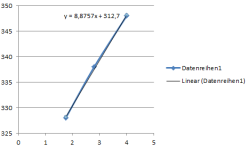
so, Excel says, that cal a has to be 8.87 and cal b -312.7


Currentsensor Calibration.PNG

Battery Current cal a =9
Battery Current cal b =-312

should be proper values.

If you set Battery Current max to 10*9-(-312) = 402 you will get 10 A maximum current.
I have to improve the code, to have the right power displayed, but that won't be a problem :wink:

honya96 said:
edit -311 starts weird, -313 also doesnt run the motor at startup but I feel like its still putting too much force after releasing throttle
can you check if the bad behavoiur occurs after longer brakes and doesn't occur, if you accelerate again, just after the motor stopped?
Perhaps you should post a video for diagnaosics.

regards
stancecoke
 
geofft said:
I've tried this with an old-fashioned crt 'scope :-
..this gave a 'rough' result for my (Q128H) motor of about 150 degrees.
I am not sure about that process of scope, I never validated, but it is interesting to see different results. Now that you have the bike training roller, you can put a constant load on the motor and adjust:
Code:
// This value at 127 is the default but a value a bit higher or lower my improve the controller efficiency
// This value can be tested with motor running at medium speed, where it is already running with sinewave interpolation (not at startup)
// A way to test: put the motor with the same mechanical load (like on a bike training roller) and with a constant speed
// changing this value will make the motor to need more or less current to mantain the same speed -- adjust to use the least current possible
// A value of FOC_READ_ID_CURRENT_ANGLE_ADJUST = 137 was found to be a good one for BMSBattery Q85 motor with S06S controller
#define FOC_READ_ID_CURRENT_ANGLE_ADJUST 137
 
stancecoke said:
can you check if the bad behavoiur occurs after longer brakes and doesn't occur, if you accelerate again, just after the motor stopped?
Perhaps you should post a video for diagnaosics.

Its ok now, seen that just a few times with wrong cal b. Thanks for the values.
 
Code:
  // (ui8_max_speed * 1000 * (ui8_motor_characteristic / 2)) / (3600 * f_wheel_size)
  ui32_temp = ((uint32_t) lcd_configuration_variables->ui8_max_speed) * 1000; // in meters/hour
  ui32_temp *= ((uint32_t) (lcd_configuration_variables->ui8_motor_characteristic >> 1));
  f_temp = 3600.0 * f_wheel_perimeter;
  f_temp = ((float) ui32_temp) / f_temp;
  motor_controller_set_speed_erps_max ((uint16_t) f_temp);
I think that code works well.
For a 46 magnets motor like yours, for a wheel of 26'' and wheel speed of 25km/h, the max erps will be: 77.
For a Q85 geared motor, for a wheel of 26'' and wheel speed of 25km/h, the max erps will be: 343.
That is a big difference... and that value will set the variable ui16_target_erps and on the speed controller MOTOR_SPEED_CONTROLLER_KP:
Code:
  i16_error = ui16_target_erps - i16_motor_speed_erps;
  i16_output = i16_error * MOTOR_SPEED_CONTROLLER_KP;
the i16_error in speed will be multiplied for the constant K MOTOR_SPEED_CONTROLLER_KP. A geared motor will always a bigger output value on that calculation...
The ratio is: 343 / 77 = 4.54. So, you can edit on main.h file and change from 2 to 9 or maybe even a little higher value:
Code:
#define MOTOR_SPEED_CONTROLLER_KP 2 // x << 5
 
I dont know what to do now, my 14s battery on the big bike is blowing 60v mosfets with main branch so I dont want to test it with the 6fet again, and I am not confident enough to risk the 18fet yet. now It has 3 shunts (can the cal a,b be set for this?) otherwise stock so like 60A max (limited by wires and traces) It has KTE-18S5-A board, 100A phase current sensor(on 12fet its 50A). only 4 things I like about running stock fw is light switch from lcd, cruise from lcd, functional reverse switch wires (great for heavy bike) and that it doesnt pull any power after releasing throttle. maybe I will just order spare 18fet tomorow so I still have one stock just in case :D

@ Stancecoke, do you think I will get that running? flashing connector is ready :twisted:
 
casainho said:
geofft said:
I've tried this with an old-fashioned crt 'scope :-
..this gave a 'rough' result for my (Q128H) motor of about 150 degrees.
I am not sure about that process of scope, I never validated, but it is interesting to see different results. Now that you have the bike training roller, you can put a constant load on the motor and adjust:

Ok, I'll try that sometime next week, will be interesting to see if it agrees with the oscilloscope result.
 
casainho said:
Code:
  // (ui8_max_speed * 1000 * (ui8_motor_characteristic / 2)) / (3600 * f_wheel_size)
  ui32_temp = ((uint32_t) lcd_configuration_variables->ui8_max_speed) * 1000; // in meters/hour
  ui32_temp *= ((uint32_t) (lcd_configuration_variables->ui8_motor_characteristic >> 1));
  f_temp = 3600.0 * f_wheel_perimeter;
  f_temp = ((float) ui32_temp) / f_temp;
  motor_controller_set_speed_erps_max ((uint16_t) f_temp);
I think that code works well.
For a 46 magnets motor like yours, for a wheel of 26'' and wheel speed of 25km/h, the max erps will be: 77.
For a Q85 geared motor, for a wheel of 26'' and wheel speed of 25km/h, the max erps will be: 343.
That is a big difference... and that value will set the variable ui16_target_erps and on the speed controller MOTOR_SPEED_CONTROLLER_KP:
Code:
  i16_error = ui16_target_erps - i16_motor_speed_erps;
  i16_output = i16_error * MOTOR_SPEED_CONTROLLER_KP;
the i16_error in speed will be multiplied for the constant K MOTOR_SPEED_CONTROLLER_KP. A geared motor will always a bigger output value on that calculation...
The ratio is: 343 / 77 = 4.54. So, you can edit on main.h file and change from 2 to 9 or maybe even a little higher value:
Code:
#define MOTOR_SPEED_CONTROLLER_KP 2 // x << 5
All this made me thinking that, doing the speed controller to control the motor ERPS (i16_motor_speed_erps) and having such big difference of that value for different motors, for the same wheel speed like 20km/h, seems not a very good idea.
Maybe the best is to instead control the wheel speed, that is independent of each motor characteristic (and even each wheel size). Still, the MOTOR_OVER_SPEED_ERPS needs to be controlled and is the same for every motor -- maybe can be controlled on fast loop, by reducing the duty_cycle every time motor speed > MOTOR_OVER_SPEED_ERPS.
 
Github user butchja (someone that seems to had register on github just to write this issue) wrote an interesting issue about improving battery reading and optimize the power output:

https://github.com/OpenSource-EBike-firmware/BMSBattery_S_controllers_firmware/issues/25
 
casainho said:
Github user butchja (someone that seems to had register on github just to write this issue) wrote an interesting issue about improving battery reading and optimize the power output:

https://github.com/OpenSource-EBike-firmware/BMSBattery_S_controllers_firmware/issues/25

"The internal resistance should be comensated so a greater range can be achieved" ???

It has nothing to do with battery level monitor but with some smart soft cut-off LVC which will lower your max amps when you start getting close to lvc voltage. Even just in theory its not easy because someone can have sag of half the usable voltage range and someone less than a volt with lipo so it will never help him.

Even with Adaptto - a really expensive controller. The soft cut-off didnt work 100% with my weak battery. Under high load it hit the lvc too fast so it just cut the power and applied back. But when not using 7kw but just 1kw down to empty battery, then it started lowering the power so I was able to get home everytime. Even just 100w walking speed at exact lvc voltage. But that way I have never run out of juice totaly, far from home

For the battery monitor, as I mentioned before, its enough to refresh only when no power applied to motor. So you go with full battery, 20km straight without ever releasing throttle, then wonder "whats my capacity left?" You release throttle, wait a second or less just so the no load voltage stabilizes. And then it changes from full (last remembered value) to 2 bars for example.

I guess it will also use less processing power than when its still jumping depending on load.
 
honya96 said:
For the battery monitor, as I mentioned before, its enough to refresh only when no power applied to motor. So you go with full battery, 20km straight without ever releasing throttle, then wonder "whats my capacity left?" You release throttle, wait a second or less just so the no load voltage stabilizes. And then it changes from full (last remembered value) to 2 bars for example.

I guess it will also use less processing power than when its still jumping depending on load.
I added this idea to that issue.
 
The issue of battery voltage sag under load is well known and documented, I think honya suggested this method of checking battery voltage only in off-load moments a few pages ago in this thread. My battery indicator (lcd3 display) is very accurate (after tinkering with the lookup table in main.h) but will often drop a battery bar beneath the true reading whilst under load and then recover when the load is removed.
I don't see this as any great problem, it's fairly obvious what's happening when you see it. It's just a minor issue really, maybe something that could be improved in the future when the major items in the code are working well.
 
geofft said:
I don't see this as any great problem, it's fairly obvious what's happening when you see it. It's just a minor issue really, maybe something that could be improved in the future when the major items in the code are working well.

I agree, actually its not even an "issue" its ok as it is.
 
"With low battery and in case of load, the raw voltage readings are be below the undervoltage threshold, but this should be permissible."

So I was right, he is talking about LVC but if I set to 2.5v per cell, I dont want the battery to have lower voltage EVER in its life time.

So no, this should not be permissible. Even under load. Think about the chemistry, if this is apliciable then you can also charge by 5 volts measure capacity charged and disconnect so you get 4.2v. But it does not work that way. PTC, CID protected cell will disconnect itself by high internal presure. Non-protected will leak or explode.

Chargers are CC CV (float charge mode is not good for lithium, rather 100mA cutoff current per cell. But most chargers still have it)

So in reverse discharging will be best that way.

Btw, with as low as 2.5v you still get decent cycle life, that voltage is not reached much often and when it is, the torque throttle helps here, you can just decrease the load. And drive home.
 
honya96 said:
I dont know what to do now, my 14s battery on the big bike is blowing 60v mosfets with main branch

@casainho: May this be a problem of too low deadtimes in PWM at higher voltages?

honya96 said:
now It has 3 shunts (can the cal a,b be set for this?) otherwise stock so like 60A max (limited by wires and traces) It has KTE-18S5-A board, 100A phase current sensor(on 12fet its 50A)....
@ Stancecoke, do you think I will get that running? flashing connector is ready :twisted:

You can try the same approach as before:
1. measure the voltage on AIN8 (Pin 23) to get a first guess for cal b,
2. find the right value for cal b,
3. measure the max current at three values of Battery Current max
4. calculate cal a out of the found values.

But you have to make sure, that we have 2.5V quite exactly on AIN5 (Pin 17), otherwise the FOC will make the commutation fail.

regards
stancecoke
 
stancecoke said:
honya96 said:
I dont know what to do now, my 14s battery on the big bike is blowing 60v mosfets with main branch
@casainho: May this be a problem of too low deadtimes in PWM at higher voltages?
Yes, can be -- maybe bigger mosfets and/or higher voltage controller version, have different power stage and need bigger dead time. I think in 2 possible ways to get it correct:
1. We would need to measure it like I documented here: https://opensourceebikefirmware.bitbucket.io/development/Motor_controllers--BMSBattery_S_series--BMSBattery_S06S--PWM_signals.html#h1-4

2. On pwm.c file, we see that 16 value that represents the 1us dead time that our firmware uses. I would increase it for 4x more, like 4us and then going decreasing up to get that problems.
I think a bigger value than what is needed is not a problem but may represents a kind of loss of efficiency.
Here is the code to be changed:

Code:
  // break, dead time and lock configuration
  TIM1_BDTRConfig(TIM1_OSSISTATE_ENABLE,
  TIM1_LOCKLEVEL_OFF,
  // hardware nees a dead time of 1us
  16, // DTG = 0; dead time in 62.5 ns steps; 1us/62.5ns = 16
  TIM1_BREAK_DISABLE,
  TIM1_BREAKPOLARITY_LOW,
  TIM1_AUTOMATICOUTPUT_DISABLE);
 
Back
Top