Mid drive vs Hub Motor for 10000 watt project

flippy said:
i would recommend using a 10K 1W resistor.

Thanks...This controller can deliver 300 amps for 20 seconds and then 100 continuous...When I re-checked on the motor stats, it is rated for 150 amps peak, but doesnt say what its rated for phase amps....
 
amps are basically the same across the board for battery and phase amps. but even that beefy motor will not survive 300A and then 100A continuous. you will fry the coils or demagniteze it well before you kill the controller.
 
flippy said:
amps are basically the same across the board for battery and phase amps. but even that beefy motor will not survive 300A and then 100A continuous. you will fry the coils or demagniteze it well before you kill the controller.

The motor on the the bike now is a qsmotor 16 inch, and no where as beefy as the one thats coming..and I pulled 65 amps peak and an easy 35-40 amps continuous with no detrimental effect...I dont think it would pull 100 amp continuous anyway especially on flat ground,but as long as the temps stay reasonable,but around 75 amps,it should handle easy considering all the copper in there.
Heck,my Crystalyte h4080 took 60-70 amps all the time with no damage.
 
You need to measure the phase-to-phase resistance of the windings. That's what will tell you the current handling of the motor. While the larger aluminum side covers and increased surface area of their sculpted shape increases the amount of heat that can be dissipated far beyond the 1kw or so that a common ebike hubmotor can shed, it still boils down to how much heat you make, and the resistance of the copper times current squared is your starting point.

The other huge factor in power handling is the load. eg I own an earliest version of the QS 273x50 motor wound for a Kv of about 18rpm/volt. I used it on a light bike in a tire with an outside diamet of 20" for a very light load on the motor. I've run that motor at over 30kw peak input on 74V nominal. The current settings were 500A phase limit and 420A battery limit. The bike had nearly uncontrollable torque and a top speed of right at 100kph with no significant heat issues. That was because the light weight and low gearing (small wheel) were a light load on the motor...so much so that it was difficult to draw the full current limits. As you add weight and increase wheel diameter everything changes in a hurry, since acceleration times increase and heat going up by the square of current becomes more apparent.

Also, while an amp is an amp, phase amps (what the motor sees) and battery amps are certainly not the same thing, and in the case of Kelly who rates their controllers based on phase current, they aren't even close to the same thing.
 
John in CR said:
You need to measure the phase-to-phase resistance of the windings. That's what will tell you the current handling of the motor. While the larger aluminum side covers and increased surface area of their sculpted shape increases the amount of heat that can be dissipated far beyond the 1kw or so that a common ebike hubmotor can shed, it still boils down to how much heat you make, and the resistance of the copper times current squared is your starting point.

The other huge factor in power handling is the load. eg I own an earliest version of the QS 273x50 motor wound for a Kv of about 18rpm/volt. I used it on a light bike in a tire with an outside diamet of 20" for a very light load on the motor. I've run that motor at over 30kw peak input on 74V nominal. The current settings were 500A phase limit and 420A battery limit. The bike had nearly uncontrollable torque and a top speed of right at 100kph with no significant heat issues. That was because the light weight and low gearing (small wheel) were a light load on the motor...so much so that it was difficult to draw the full current limits. As you add weight and increase wheel diameter everything changes in a hurry, since acceleration times increase and heat going up by the square of current becomes more apparent.

Also, while an amp is an amp, phase amps (what the motor sees) and battery amps are certainly not the same thing, and in the case of Kelly who rates their controllers based on phase current, they aren't even close to the same thing.

Wow...lol..that's insanity...30kw??..I dont even want to know what the torque numbers were..lol

Yeah,so with a high gear (16 inch motorcycle wheel) and heavy weight, it will def draw some amps on take off...Here are some of my assumptions;

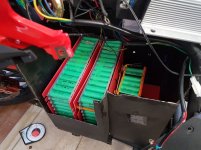
1) Battery pack consisting of 24s 14p cells capable of 20 amps discharge each=280 Continuous amps or 350 peak amps, so its inline with the Kelly Controller at 300 amps for 30 seconds.
2) I am assured that the motor can take this for this period of time as long as the internal temp is within limits.
3) After the bike starts moving this will obviously taper off.
4) As long as the motor is not within it's saturation limit, and let's say for example going 40 kph (from a theoretical top speed of 90 kph),it probably wont pull anywhere near 300 amps but should be around the 100 amp continuous limit for the controller untill you begin to reach saturation at which point amp draw falls to whatever it takes to maintain the top speed?
5) Obviously a tall gear (16 inch motorcycle wheel vs 20 inch bike wheel) is going to load the motor much more than a short gear, but I think this is minimized once the bike is moving...
6)I have already calculated (using the cycle analyst) that maintaining 55 kph on this bike requires between 1400 and 2300 watts. ..so roughly doubling the speed would require 4 times the power or 5600 watts minimum (perfect conditions) or 9200 watts at most, and that is just to maintain that speed
 
Battery build is next for this project and will start new thread for it and rest of the build

The cells came in from NKON, this time in good time and order.

batteryparts.jpg20180209_141130.jpg20180209_141112.jpg

I printed up the batt holders and nuts and bolts that hold everything together. A huge battery consisting of Samsung ICR18650 -25r cells...24s x 14p. Once I am finished with all the 3d printed parts then, the build will begin..

John
 
johnnyz said:
5) Obviously a tall gear (16 inch motorcycle wheel vs 20 inch bike wheel) is going to load the motor much more than a short gear, but I think this is minimized once the bike is moving...

16" moto wheels come in many sizes. Some of the narrowest result in an OD under 20". I have one of those, as well as bicycle tires that go on a 20" rim, but are over 21.5" OD.

Regarding the effects of a large wheel being minimized once moving, it's not the case except when coasting. At all speeds, during any acceleration, into any headwind, or up any incline, the motor will draw more current for a given level of performance than it would in a smaller wheel. With hubmotors my advice always is to run the smallest wheel you can live with in terms of ride quality and looks.
 
Well...the wheel is the wheel...and its rated for 6000 watts continuous and 10500 peak...frankly I think it will easily exceed these numbers as I have used Crystalyte hub motors in this range and they survived...

The biggest thing now is the battery build..I am not an electrician but am making educated guesses as to gauge of wire/amps drawn...since the battery is large (24 s 14 p) the only way to fit in the battery box space was to divide into 3 sections..the section housing the positive of the battery will have 8 gauge connecting to the second battery..and the second battery connecting to the first will have 2 8 gauge wires connecting it, since the first connection is very short (see pic)
Each series main wire consists of 2 10 gauge solid core copper wire soldered together (effectively making the main series wire 7 gauge (https://www.wirebarn.com/combined-wire-gauge-calculator_ep_42.html),so this out to handle the full pack amperage of 100 amp continuous and 300 amp for 3 seconds or so..
 
not to be "that guy", but you are spending quite a bit of money on this endeavour.

why not spend another 100 bucks for a proper spot welder and a roll of nickel strip and do it proper? also it makes the pack a lot flatter and more robust.

also: you need 6AWG for proper connections with these amounts of current. the pack once built is capable of vaporising the cables if something shorts.
 
flippy said:
not to be "that guy", but you are spending quite a bit of money on this endeavour.

why not spend another 100 bucks for a proper spot welder and a roll of nickel strip and do it proper? also it makes the pack a lot flatter and more robust.

also: you need 6AWG for proper connections with these amounts of current. the pack once built is capable of vaporising the cables if something shorts.

lol...trust me I know..the money is flying out of my wallet...

Spot welder...you mean this piece of shit??20180213_093406.jpg

I have been there and done that...yeah paper thin expensive nickle strip is NOT and I repeat NOT what you make a high powered battery pack from..I did this to a 24s 8p pack a while back and trying to draw 65 amps resulted in all the series connections turning blue and purple from the heat...I then doubled and tripled on the series connections to have the resistance drop from .500 ohm to about .300 ohm...I then said screw this and did a tesla style pack with 10g solid copper wire and 20g on the p connections and viola a full 65 amps appeared along with a drop in resistance to about .180. Since then I have built about 20 of these packs and they are beyond great..
I put together (2) 10 g solid copper wires for the series connections which brings it to 7 gauge and using 18 gauge solid copper on the parallel connections..should be ok for a 5 second 280 amp draw??.On the power positive and negative cables I am using a 10 g and 8 gauge wire which is in effect 6 gauge.I am taking an educated guess here I admit...but I know this easily survives 100 amp prolonged current.

Thanks for the comment!
 
Well...here is the first or should I say the smaller module done..it has 3d printed mounts that will be bolted to the frame battery box on the bike..thick plastic covers front and rear so that nothing will touch anything that isnt suppose to touch.
20180213_131624.jpg
20180213_131607.jpg

The 3 battery modules place loosely in the battery box so i can see if they will fit in this orientation,which they just do...
 

Attachments

  • 20180211_142409.jpg
    20180211_142409.jpg
    52.8 KB · Views: 2,820
johnnyz said:
flippy said:
not to be "that guy", but you are spending quite a bit of money on this endeavour.

why not spend another 100 bucks for a proper spot welder and a roll of nickel strip and do it proper? also it makes the pack a lot flatter and more robust.

also: you need 6AWG for proper connections with these amounts of current. the pack once built is capable of vaporising the cables if something shorts.

lol...trust me I know..the money is flying out of my wallet...

Spot welder...you mean this piece of shit??20180213_093406.jpg

I have been there and done that...yeah paper thin expensive nickle strip is NOT and I repeat NOT what you make a high powered battery pack from..I did this to a 24s 8p pack a while back and trying to draw 65 amps resulted in all the series connections turning blue and purple from the heat...I then doubled and tripled on the series connections to have the resistance drop from .500 ohm to about .300 ohm...I then said screw this and did a tesla style pack with 10g solid copper wire and 20g on the p connections and viola a full 65 amps appeared along with a drop in resistance to about .180. Since then I have built about 20 of these packs and they are beyond great..
no, mean a proper welder like this:
https://malectrics.eu/product/diy-arduino-battery-spot-welder-prebuilt-kit-v3/

the regular cell interconnects only see the current flow between it and the next cell. do there is not 100A+ flowing tru a strip, only the ~10A or so that each cell is discharging at to the next cell. a regular real nickel strip 8x0.15 can manage that without issue and duration.
now at the end of the pack were the current off all cells come together to need to use bus bars as you have. but for between each cell group you dont. just 15 strips to the next set and one additional trip across them to equalize the group.
example here:

PlgW55Cl.jpg

this way you spread the load equally over all strips and each strips only sees a fraction of the total current. not a problem for nickel strip. much faster, cleaner and less suseptible to breakage.
if you use low P numbers of cells and go beyond 10A constant load per cell you need thicker strips like .3. doubling up .15 does not work because the current still has to go tru the first strip.
 
Here is a list of the conductivity of various metals...


Material IACS (International Annealed Copper Standard)
Ranking Metal % Conductivity*
1 Silver (Pure) 105%
2 Copper 100%
3 Gold (Pure) 70%
4 Aluminum 61%
5 Brass 28%
6 Zinc 27%
7 Nickel 22%
8 Iron (Pure) 17%
9 Tin 15%
10 Phosphor Bronze 15%
11 Steel (Stainless included) 3-15%
12 Lead (Pure) 7%
13 Nickel Aluminum Bronze 7%

As can be seen copper is 5 times the electrical conductivity of nickle. Between each group of PARALLEL cells which by definition is the SERIES of the battery pack, sees the FULL current of what ever is coming out of the positive and negative ends of the pack.

Example: My pack which has 24 SERIES of 14 Parallel strings of cells. If I am drawing 100 amps through the negative and positive ends of the battery pack, the the parallel group of cells will see 100/14=7.1 amps each, hence the connections between them has a relatively light amperage load. The series connections will see 100 amps flowing through it, on EACH and every series connection.
If I draw 250 amps then the P connection of cells see 17.8 amps and the series connections 250 amps!. If you think you can put that kind of amperage through ANY kind of nickle strip on the series connection, I would like to see it. Besides I said that I tested the resistance of the first pack I made using nickle strip and the resistance was huge (as measured through the CA)..so much so that the bike would only pull about 20 amps (controller set for 65). and a resistance of .500 ohms!..when I tripled up on the series connections, the resistance dropped to about .300 ohms and the amps I could pull increased to about 32 amps. When I ripped it all off, and replaced the series with 12 g solid copper the resistance dropped to about .220 ohms...I then re-did it using tesla style connections and 10 g solid copper wire and 18 g p connections the resistance fell to .180. I have made many batteries using this formula and the average resistance is .140 ohms.

I will make this battery in this way and then test it after when the new controller and motor arrive. Will give results and data.

Ya its a pain to do it this way but I want the best results.

By the way, after 330 cycles using the Panasonic cells, that were soldered 3 different times, abused, drawn more current then their rating, overheated,etc..I tested 3 cells out of the pack, and the capacity was still around 92 %. The only thing I can attribute this to would be that I never really fully charged the pack and almost always charged when it got to about 84-86 volts (86/24=3.5 volts each).

Thanks for the comment!

John
 
Well....the Controller, Contactor and cable for communication port for controller to computer arrived..20180221_080020.jpg

However, a number of things are wrong already and this really really annoys me..

First, there is no converter to tie in the RS232/USB plug they sent to the Kelly Controller.20180221_080108.jpg

Second, the "kit" to connect all the wires via the DJ7091Y connectors are incorrect...There are 2 female and 1 male connectors on the controller and in the kit they have only 2 female connectors not three, but just 2 and the body of each wont fit into the body of the Kelly connectors anyway..lol..am I missing something here?20180221_080031.jpg20180221_080230.jpg20180221_080215.jpg

Also, I told DAMON I have a 100 volt battery and he sends me the KLS8430H. Rated for 24-84 Volt..He asked me what the max charging voltage for my pack and I said it would be 99 volts (I only charge to 4.15 volts), and he said this controller would be fine...why do I have a bad feeling about the longevity of this connected to my new pack???
 
The motor is here....wondering if anyone can tell me (as Damon isnt answering my emails)...if this added wire coming from the hall sensor plug is the temp sensor in the motor?..it also has an extra hall set..I did ask them to install one and they said they would, but then again I asked for a disk brake and they said yes, but alas, no brake..motor.jpgView attachment 2View attachment 1extrawire.jpg


Thanks
 
the middle wire should be the temp probe.

you can plug the negative and the temp wire directly into a multimeter that has a ktype sensor input. if you get weird readings you have the polarity reversed.
 
flippy said:
the middle wire should be the temp probe.

you can plug the negative and the temp wire directly into a multimeter that has a ktype sensor input. if you get weird readings you have the polarity reversed.

Hey ...thanks for the response..yup you are right..Damon contacted me and confirmed that this is the temp probe...

I have to say this motor is HEAVY!!!...I took it to a motorcycle shop today and they are gonna put a new tire on it tomorrow...it is .75 inches wider and the phase wires are 6 gauge!!, compared to the 10 g on the old QSMOTOR hub motor. I am getting so excited to get this thing working...still havent finished the battery, but when thats done then the controller,and motor hookup...
 
I would love to see the inside of that thing. And see the difference between this and a standard chinese motor.
 
flippy said:
I would love to see the inside of that thing. And see the difference between this and a standard chinese motor.

Its big and heavy, I would say 20 pounds more than the qsmotor that was on it..here is what the side looks like...although it is offset, its a full 3 inches wide vs 2.1 inch for the old motor.

Will post more pics and battery build when I get time..

John
 

Attachments

  • motorside.jpg
    motorside.jpg
    38.2 KB · Views: 2,634
Been so busy with everything...have not had a chance to post...the bike is done and have had to limit the speed for compliance. I made the bike because I had someone who wanted it for the street (he will licence it). I will be posting results, pictures, mileage,etc very shortly...the bike is beyond my expectations...


John
 
Back
Top