Battery amp Vs phase amp?

macribs

10 MW
Joined
Jul 22, 2014
Messages
3,702
I got into a jam today, after riding I let a couple of guys test ride it. All well and good. They got the grin and was all happy.
There was one that was rather tech savvy and he fired questions to me as fast as I could answer. But two I couldn't explain. So I can of goofed it laughed about it and told him to google it. Truth was I was out of my league and didn't know.

Assume that wires are fat, motor is big and strong enough to take all what the controller is delivering lets say a dragstrip.

1: What is the relationship between battery amp and phase amp?

2: To max out a controller that has max phase amp say 350 A or even 600 A, how much battery amp is needed?

I did as best I could and tried to remember what I've read here. So I told the controller will up the battery amp for each cycle of the three phase. So that one phase get as much amp as needed, load low slow turning motor uses less voltage more phase amp and vice versa. Then I said something about a rule of thumb being phase amp are 2.5 - 3.0 times battery amp. Thinking of this now I am not sure what I said made any sense at all :)

And the second Q I could not answer at all :oops:

A little help would go a long way so I will be more enlightened next time around. And not end up standing like stuttering fool.
 
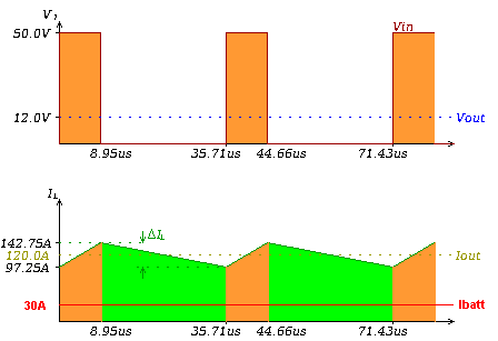
Maybe this picture helps:
buck_plot.gif

In the bottom diagram the battery current is shown in orange colour and the phase current is shown in orange and green colour.
The phase current is 120A and the battery current is only 30A...
Usually phase current is limited through peak current (in this case ~143A).
It is obvious that peak phase current is passing through the battery. The capacitors inside controller cannot reduce this peak current much as aluminium capacitors are useless at high frequencies.

The picture above is in fact diagram of the buck converter, but it is applicable in this question too.
The battery current limit is simply sorted through limiting average current and the phase current limit is achieved through limiting the peak current through the output stage.
 
I had a few minutes to kill, so I scanned some ES Googles:

from NeilP
I would say...use XPD rather than Lyen /keywin software..then you can turn block time down to 0.1 seconds

Greater phase current gives more acceleration....I think......try various settings and see...up to about 2.5 to 3 times the battery current. So try phase current up to 90A with your battery current set at 30 amps...I have my 18 FET lyen 4110 set at...80 or 90 amps battery, can't remember what the phase is set at. I do see peaks of 130 amps battery even with over-current detection set to 0 seconds

from madin88
roughly you can say:
High phase amps = good acceleration from zero to mid speed
High battery amps = good acceleration from mid to top speed
You don't have to set up phase to 2,5 x battery amps. Just do it how you like.

For higher efficiency, lower phase amps is better. You can also save some energy if you pedal from a dead stop to a few km/h and then very slowly open up the throttle

from gwhy!
There is really no right or wrong answer for the amount of phase current limit...a ball park figure is 2.0 - 2.5 x battery current, The trick is to get the right balance and the best way ( well my way, and it may not be the best )to do this is to start with around 1.2 x battery current then go out for a ride ( with a watt meter fitted ) and see if the current limit set in the controller is being reached, if the max current is below the set current limit then up the phase current to 1.4 x battery current and so on until the max battery current limit is being reached this will then be your optimum phase current level. The motors and gearing I use this is normally around 1.4x battery current, but...on a hub motor I would expect this to be a higher level more like 1.8x battery current. You can go a little higher and this, and it will improve the low speed torque but this will very much depend on other factors. I have yet to find any benefit going over around 2.2x battery current on any of the motors/setups that I have played with... but that's not to say that will not benefit all setups...

...if you go too high with the phase current you could pop your controller if the motor is really chugging and the throttle speed is being dragged down to much, a standard 12fet controller should be ok for around a safe max of around a total of 150A phase current ( can be ok up to around 200A, this depends of the type of fets in the controller and the setup ( motor and gearing ) if I was you, I would play it really safe and do no more than 100A phase current. So if your Battery current is 50A, set phase current to no more than 150A ( 3x battery current ) or be extra safe and use 50A battery and a phase of 100A ( 2x battery current ). As NeilP said set the block time down to 0 this will ( should ) limit the current as fast as possible if a over current situation occurs. The optimum settings will just be the less stressful ( but working 100% correct ) settings for the controller...

from John in CR
The way I do it is to first determine the proper ratio for that motor controller combination. Set the battery limit at modest power and set the phase limit the same, 1:1 ratio. No field weakening or overspeed settings. Spin it up no load, and also give it a road try up to max speed, so you can hear and feel what the motor is like when starved of phase current on takeoff and at the top end. Often it won't even spin up to full no-load speed. In small increments increase phase current until it doesn't sound or feel starved of current, but you're not looking for hard launch yet. Once it seems to be functioning and sounding correct at that modest power level note the phase:battery limit ratio.

Now start turning both up at the same time and maintaining that ratio until you get to the desired power and thrust on takeoff that you want. The end result will be higher power than you had the other way, but the motor and controller will be less stressed, ie less heat, especially under load at lower rpm. FWIW, Zombiess used a similar approach to come up with a 1.8:1 optimum ratio for his 4t Cromotor...

...It sounds like your battery is the limitation, because the controller can go higher. The relatively soft acceleration is the lower Kt, torque per amp, of a high Kv motor, which needs proportionately higher current. The already warm controller is in large part due to that controller brand struggling with the lower inductance of high Kv motors.

The penalty of using high phase/battery current limit ratios is excess motor heat. More torque means more heat. When you tune so high that launch torque can easily flip the bike or throttle response is too jerky, then what seems cool and powerful comes back around and bites you in the ass in the form of heat, especially at partial throttle under higher loads like off road up hills.

Instead of extra waste heat at low speeds your new settings gives you more real power and acceleration through the mid-range where making some extra heat isn't such a danger to your motor.

ghwy!
set battery current to something safe i.e 40-50A , set over-current detection to 0.0s ( this is very important ) set phase to approximately 1.5x battery current. You need a watt meter, or amp meter or calibrated ca on the bike. On a slightly uphill ( maybe a 2-4% grade) piece of road accelerate hard ( from stop ) up to top speed or until it stop accelerating but throttle is at WOT( this may take a while so you need a longish stretch of road ) then check watt meters max current pull, if the max current pulled is less than your set battery current then you need to increase the phase current, maybe by 10A or if the set battery current is reached then reduce phase current by 10A. You keep increasing or decreasing the phase current until the max current pulled from the battery is what you have set it to. Once you have found a battery/phase ratio where the max battery current is always reached then this will be the ratio you would use when increasing the battery and phase current together.

If the phase current is too low, then you will never reach full speed or max battery current. My controllers use a ratio of around x1.7 for the motors, gearing , my riding style and total weight of my bikes

Another method I have used is set at a much lower battery limit maybe 20A and a phase limit of 30A with the wheel off the ground go WOT and then start applying the brake to slow the driven wheel down ( loading the motor ) when the wheel is appox half the max speed, watch the battery current on the watt meter this should go to your set max battery current and should stay there as the driven wheel gets slower and slower until the controller cuts out ( locked rotor fault protect ) and the same applies increase or decrease phase current until you see the set max battery current limit hit, always just before the controller cuts out. Each test only needs to take around 5 secs so its a much quicker method of finding the optimum phase setting for the motor.

Once you have found your optimum phase ratio you can always turn the battery current down and keep the phase limit at the optimum.
 
The phase (motor) current to battery current ratio is changing all the time, it is not fixed. It is the result of battery voltage being down converted to drive the motor.

The phase current controls torque and resistive heat generation which dominates motor efficiency at low to moderate RPM. Phase current can be 10 or more times the battery current at low speed.

Phase current makes torque, up to magnetic saturation. Then it still makes torque but it increases at a much lower rate (per amp). It is best to set max phase current to no more than the point where magnetic saturation begins (and is compatible with wiring and connector capacity), though you might want to set it slightly higher, but heat is going to be a problem if you run at that level very long. Don't worry about the ratio, worry about the max current. Calculate the i squared r heating and think about your motor dissipating all that heat and how hot it will get.

Phase current squared makes heat in the motor. So you quickly overheat with high phase currents for only a modest improvement in torque, because the square grows so fast.

The battery current determines the max power, and should be set for battery, BMS and wiring capacity (or less).

I set the phase current to control the front wheel lift (if nothing else limits it first). No point in throwing the front wheel skyward too quickly, that's just wasted torque.

Then you set the battery current for the maximum power you want.

If that doesn't accelerate quickly enough you need to start changing equipment.

Setting the phase amp limit doesn't directly control the phase amps, it just causes the controller to limit PWM when the phase current approaches the limit. Only PWM is controlled. That is effectively controlling the voltage the controller sends to the motor. If either the phase current or the motor current exceed their limits the PWM is what is actually limited, which causes both battery current and phase current to stop increasing.
 
Sorry I couldn't help.

BTW, just doing a search on topic title for the title of this thread finds several other threads about this:

https://endless-sphere.com/forums/search.php?keywords=Battery+amp+Vs+phase+amp&terms=all&author=&sc=1&sf=titleonly&sk=t&sd=d&sr=topics&st=0&ch=300&t=0&submit=Search


Another search just for
Battery Phase
finds
https://endless-sphere.com/forums/search.php?keywords=battery+phase&terms=all&author=&sc=1&sf=titleonly&sk=t&sd=d&sr=topics&st=0&ch=300&t=0&submit=Search
 
Hello, Can some one start from the basics for me as i'm trying to work out what the battery / phase ratio is all about???

- I'm still trying to work out the obvious question (well obvious to me) of how the phases do or can flow more current than the battery does.

- if the battery isn't supplying this extra current then where is it coming from?
- is it the presence of capacitors which can give a spike to the phase current?

can anyone explain with a basic circuit diagram. i'm used to the old rule that you follow a current around a circuit which stays the same unless it splits and then you split it. it' doesn't grow bigger after leaving the battery!!
 
OK i read this on another thread. Are we talking about a step down transformer in the controller???? Hence the step up in current?

"The controller can be viewed as a voltage converter, down converting the battery voltage to the motor voltage. There is a power balance so battery current times battery voltage equals motor current times (back EMF plus motor current times motor and wiring resistance)(minus the small losses in the controller itself)".

Shouldn't it be.... (Vbattery * current) = (phase back EMF * current) + (total circuit resistance * current^2). The current should be the same all the way through.
 
Hi esust.
I'm no electronics expert so this is not an accurate answer.
From what I read, the controller and motor windings act like a buck converter (similar to a transformer) which causes the motor to get higher current at a lower voltage. The power (voltage X current) stay the same because of energy conservation.

the subject was discussed on this thread:
https://endless-sphere.com/forums/viewtopic.php?f=2&t=35278&p=1243283&hilit=phase#p1243283

Avner.
 
ferret said:
From what I read, the controller and motor windings act like a buck converter (similar to a transformer) which causes the motor to get higher current at a lower voltage. The power (voltage X current) stay the same because of energy conservation.
Yup, read up on the buck converter on Wikipedia or your preferred electronics resource. Power (V*I) is the same on both sides, but on the battery side you have higher V and lower I, and on the motor side is lower V and higher I.

This is a switching circuit, so there are two different states - there's not just a single loop around which the current has to be constant. When the switch is on, the battery feeds current to the motor, but with the switch off, the battery current is zero while the motor current continues to circulate. Thus if you average over a switching cycle the average currents can be different. It's more complicated than this with capacitors and inductors (actually the motor winding) to store energy and smooth things out over a cycle, but the average-over-a-cycle principle holds.
 
The motor is not fed by the battery. It is the controller that is pulling DC current from the battery, then is feeding current bursts to each phase alternatively. The controller program is managing how and when the current is fed to the phases, and can be set to feed a certain (battery to motor) current ratio, among various other settings. This alternative power feeding pattern to the phases is determined in the form of waves, that can be defined in length and amplitude.
 
MadRhino said:
The motor is not fed by the battery. It is the controller that is pulling DC current from the battery, then is feeding current bursts to each phase alternatively.
When you turn on a lamp, do you say that the switch pulls current from the wall and feeds it to the light bulb? OK, potato, potahto.

The controller program is managing how and when the current is fed to the phases, and can be set to feed a certain (battery to motor) current ratio, among various other settings. This alternative power feeding pattern to the phases is determined in the form of waves, that can be defined in length and amplitude.
Since the question was about current conversion, I figured I'd focus on regulation switching and not muddy the waters with commutation switching. Explaining how these interact in different types of controllers is an interesting subject, but I think we're looking for the basics here?
 
cycborg said:
When you turn on a lamp, do you say that the switch pulls current from the wall and feeds it to the light bulb? OK, potato, potahto.

No I don’t, because the lamp would work without a switch. Your logic would make me say that water is making this text on my computer screen, since power is coming from a hydro turbine and my computer is plugged on the grid.

If your motor could be fed by the battery, the ratio would be 1:1, minus circuit losses.
 
cycborg said:
MadRhino said:
The motor is not fed by the battery. It is the controller that is pulling DC current from the battery, then is feeding current bursts to each phase alternatively.
When you turn on a lamp, do you say that the switch pulls current from the wall and feeds it to the light bulb? OK, potato, potahto.

If the switch is electronic and is doing conversions and controlling the bulb, like with a CFL or LED, then yes, that is exactly what it does.

Exactly like a motor controller.

A motor controller is not a "lightswitch" feeding a simple incandescent bulb, and that is why it is more complex than you think it is.


Since the question was about current conversion, I figured I'd focus on regulation switching and not muddy the waters with commutation switching. Explaining how these interact in different types of controllers is an interesting subject, but I think we're looking for the basics here?
If you want the answer, you have to talk about all of it, becuase that is why it is the way it is. In a multiphase motor controller, that *is* the basics.

If you had a brushed motor controller, then it would be simpler as the commutation is handled inside the motor, mechanically.

The thread you posted this in the first time already has some good explanations of what is going on, as does the one Ferret linked above.

There are also threads about how motor controllers work that will tell you more. Check the Sticky Index threads in the Motor Technology section.
 
amberwolf said:
If you want the answer, you have to talk about all of it, becuase that is why it is the way it is.
OK. Give me a few years to construct and solve the quantum wave function for the battery-controller-motor system and I'll get back to you. If someone beats me to it, awesome. But don't post anything else, because you won't be talking about "all of it".
 
I'm sorry, that's not how I meant it--just that from the reply about the switch / lamp, it seemed that you didn't understand the conversion that's going on, and I guess I missed that you did. :oops:

I also meant part of my reply (about the previous thread posted in) to be for the OP of this thread, and not you; the way the forum displays posts now after the "upgrade" I sometimes miss who posted what and I probably mixed up his questions with your replies when I was replying. :oops: :(

I've gone ahead and edited my previous post down to itsy bitsy text with an "ignore" note (since the post history feature doesn't exist anymore) so the context of your reply to me isn't lost (otherwise I'd just delete my post, since it's messed up and wrong anyway). If you like, you can ask a moderator to just remove these three "OT" posts entirely, as irrelevant to the thread, and I'll just stay away from it.
 
No worries, just a difference of opinion on too little vs. too much information. For an OP with a post count of 3 who asks to start from the basics, I'm inclined to err on the side of the former. I also try to give some clue that my knowledge extends beyond my answer, but I may tend to err on the side of subtlety.
 
I agree that I could have made it more basic:

‘Motor phases are fed more Amps than supplied by the battery, for the same reason that flushing the toilet does release more water than the tap.’

:mrgreen:
 
I recommend this article:

https://en.wikipedia.org/wiki/Buck_converter

During the off state, current flows through the diode (or FET in a synchronous system) and keeps the current going through the motor winding even though the battery is disconnected at that point. I've done measurements on one of my motors and could get about 3x more motor current than battery current at low speeds.
 
Back
Top