Common pack design mistakes, how to avoid?

As promised, the schemas of my connections:
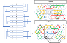
Parallel connection.png

And the final result on my bike will look like that:
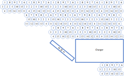
Bike triangle.png

In the first picture, you can see the connections. The positive of the 15P pack will come out of the cell no5 and the negative out of cell no13. In theory, if the motor wants to draw 30A, the gray strips connecting cell no5 to cell no2 and no10 will carry 15A each direction. Then, the yellow strips connection no2 to no1 and no4, as well as the ones connecting no10 to no7 and no15 will carry 7.5A on each branch. etc, etc. You get the idea.

Each 15P pack will be connected in series to the next and also give a small feeback to the BMS for the voltage balancing. The complete triangle pack will have one input at the back for the charger to go to the wall socket as well as one output cable that will reach to the rear bike rack and connect to the motor controller.

As I previously mentioned, I need a material that can cope with the 15A. I don't want the packs to overheat or the cells to get burnt because of the strips.

Any feedback is highly appreciated! :D
 
I landed here for my 1st build, I have to admit that this is a very informative thread to thoroughly read through should you proceed to build your own pack.
There's one section that is more important that this thread does not cover ... Failures. Reviewing failures over the vast resource called the internet, eliminated over 60% of the builds that have been posted here, and the other 40% of well designed packs can have their best attributes extrapolated for a near perfect build.
Cells really do dictate the builds as to hoe they should be setup so not to over tax or wear them out due to poor current flow design.
Eliminate the fails in your designs and that leaves you with the good builds to draw from.
 
brumbrum said:
Maybe ok for 30a draw, but you may find over time that the cell voltages begin to drift apart as some cells are taking the strain more than others.... In theory.

I really have to wonder about this "theory". If the cells in a parallel group started to "drift apart" -- by which I take it you & others) mean some cells will discharge more than others, thus reaching up at a lower voltage than those others, then the moment the demand eases off -- you shut the throttle -- the differential in voltages within the parallel group will cause a current flow from those with the higher voltage to those with the lower, effectively self-balancing the group.

I find it almost inconceivable that the tiny extra resistances between the cells at one end of a parallel group, and those at the other would be in any way sufficient to affect the long term health of the individual cells, regardless of whether the serial connection to that group is made at one end of the pack or the other.

And nothing I've read on the subject outside of this thread has even mentioned this as a possibility.

It seems to me that someone -- the OP? -- had the notion and posted it here, and it has gradually gained currency based purely upon that supposition. And the idea that people are inventing ever more elaborate connection schemas to try and counter a theoretical possibility that no one to my knowledge has provided the slightest piece of actual evidence for, just seems crazy.

Update: I just saw the link below where there are some calculations suggesting that in a 4P group, one cell is drawing 35.9% of a 100A draw, because of a 0.0015 Ohm resistance in the links between the 4 cells. Did anyone with good math/EE knowledge verify those figures, because they do not look right to me.

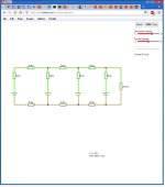
Update 2: I drew up a circuit equivalent of a 4P group connected to a load drawing 100A via 10mm x 0.15mm x 18mm long connections at http://www.falstad.com/circuit/circuitjs.html which can be recreated by importing this text file:
Code:
$ 1 0.000005 10.200277308269968 50 5 43
r 48 128 160 128 0 0.000008388
r 224 128 320 128 0 0.000008388
r 384 128 464 128 0 0.000008388
r 48 320 160 320 0 0.000008388
r 224 320 320 320 0 0.000008388
r 384 320 464 320 0 0.000008388
w 16 128 48 128 0
w 16 320 48 320 0
w 160 320 192 320 0
w 192 320 224 320 0
w 320 320 352 320 0
w 352 320 384 320 0
w 464 320 496 320 0
w 496 320 576 320 0
w 160 128 192 128 0
w 192 128 224 128 0
w 320 128 352 128 0
w 352 128 384 128 0
w 464 128 496 128 0
r 576 128 576 320 0 0.0295
v 16 320 16 208 0 0 40 4.2 0 0 0.5
r 16 208 16 128 0 0.05
v 192 320 192 208 0 0 40 4.2 0 0 0.5
r 192 208 192 128 0 0.05
v 352 320 352 208 0 0 40 4.2 0 0 0.5
r 352 208 352 128 0 0.05
v 496 320 496 208 0 0 40 4.2 0 0 0.5
r 496 208 496 128 0 0.05
w 496 128 576 128 0

It looks like this:
PgroupEquivCircuit.jpg

And when I mouse over the 4 cells, the current draw from each of them, left to right is:

24.97A
24.98A
25.00A
25.02A

I find it hard to believe those differences would be significant?
 
I really like your tool Buk! I'm gonna have some fun with it as soon as I get some free time. :)

I don't know if it's actually a big problem or not... however, even you see differences between the cells in just 4P. I know they are very small, but I have 15P to build and some people build insanely big packs with many parallel cells. Don't you think there might be some truth in what the article I posted says? If you want to get the absolut best out of your cells, I believe you need to consider all the posibilities.
 
I think in the link to the SmartGauge 4P-example they have 20 cm length between each battery? With 18650 cells it is more like 2 cm? And they add resistance to each connection but if you have like in my example lika a "bus bar" there is only one connection to each cell regardless of how many P. And they use 100 amps on 4P... I dont use that but I guess many other people here do.

But I guess they talk about paralell connect several battery packs, not cells?

http://www.smartgauge.co.uk/batt_con.html
 
Buk, it looks like you have modelled the interconnects as 8.4 micro-ohm resistors? Your earlier mention 0.0015ohms (1.5 milli-ohms [1500 micro-ohms]).
 
For 18650 builds where each cell is somewhat limited in how much current it can push, I don't think the current sharing is a big deal. I would be much more concerned with keeping the current below the safe limit for the nickel strips. If each cell has its own series connection to the next cell, very little current needs to flow in the parallel connection (except for the pack ends).
 
Thanks for the replies! Fechter, I have to put the batteries in parallel first because I want to place them in the bicycle triangle.
The main problem with that is that I would need more than one BMSs (In fact, up to 15 BMSs).
Connecting them in parallel first, I only need one BMS to capture and manage the voltage of each 15P pack.
I agree with you that the nickel strips is a bottleneck and more serious issue. For a 30A draw, what would be the ideal size of the nickel strips to avoid temperature issues and have the least voltage drop at the same time?
 
Punx0r said:
Buk, it looks like you have modelled the interconnects as 8.4 micro-ohm resistors? Your earlier mention 0.0015ohms (1.5 milli-ohms [1500 micro-ohms]).

The earlier value came from the link above. The 8.4 uOhms is my own calculation based on 10mm x 0.15mm x 18mm nickel between cell centers using Pouillet's law:

R = p * l / A = 6.99×10−8 * 0.018 / ( 0.01 * 0.00015 ) = 0.0000000012582 / 0.0000015 = 0.0008388 Ohms

Which suggests that I must have made a mistake when cutting and pasting from the calculator to the simulation :( It should be 838.8 uOhms.
 
Punx0r said:
Buk, it looks like you have modelled the interconnects as 8.4 micro-ohm resistors? Your earlier mention 0.0015ohms (1.5 milli-ohms [1500 micro-ohms]).

Okay. Having corrected my transcription error, this is how the simulation looks: Falstad simulation of 4P group drawing 100 amps.

And the individual cells draws are:

23.09 A
23.86 A
25.44 A
27.86 A

A bigger (18%) difference end to end, but hardly the 200% difference shown in the link.

And if you make the cell internal resistances a more realistic 100 mOhms rather than 50 mOhms, then the end to end difference drops to less than 10%

4P 100A 100mOhm cell resistances.
 
tsourorf said:
I agree with you that the nickel strips is a bottleneck and more serious issue. For a 30A draw, what would be the ideal size of the nickel strips to avoid temperature issues and have the least voltage drop at the same time?

I'm sure this has been figured out by someone already but I don't know the answer. 0.15mm nickel, 8mm wide is good for 5A from experience.

One approach I've seen used is to use a sheet of nickel that covers all the cell ends you want to connect. This can save some time not dealing with hundreds of little pieces.
Another approach is to use nickel strips on each cell, then solder copper wire to the strips. 12ga copper can easily handle 30A.
 
Buk___ said:
And the individual cells draws are:

23.09 A
23.86 A
25.44 A
27.86 A

A bigger (18%) difference end to end, but hardly the 200% difference shown in the link.

And if you make the cell internal resistances a more realistic 100 mOhms rather than 50 mOhms, then the end to end difference drops to less than 10%

4P 100A 100mOhm cell resistances.

I like this simulation. It shows what many battery builders don't know.
But a realistic IR value for high current 18650 is about 20mOhm :wink:
 
madin88 said:
But a realistic IR value for high current 18650 is about 20mOhm :wink:

Hm. I checked the Samsung specification document for the cells I have ICR18650-26H, which reads:
7.3 Initial internal impedance
Initial internal impedance measured at AC 1kHz after rated charge.
Initial internal impedance ≤ 100mΩ

I also read about various methods of measuring DC resistance rather than AC impedance, but there seem to be as many methods as there are people doing independent tests; and even performing the same method seems to produce variable results and always higher than the manufacturer's AC impedance values.

In the end, the nice thing about the simulation is that its free and easy to change the values, so anyone can change them to suit the cells and connections they are using.
 
I can believe the 100mohm figure if these cells really are 5A max discharge like this link suggest (proper datasheet is hard to find)! http://www.candlepowerforums.com/vb/showthread.php?389665-Samsung-ICR18650-26H-2600mAh-(Pink)

You say the ~5A spread in current across the cell group you simulated isn't significant, but calculate the difference in voltage that would represent. Also consider a constant discharge in that scenario. Normally we consider paralleled cells as being at equal state of charge but in your simulation they are not, before the BMS detects the average cell voltage of the group is at LVC, some of the cells will have been driven well below it. Fast charging represents an opposite scenario. Intermittent discharge means the some cells being rapidly charged by the others when the current demand on the pack is reduced. All these effects cumulate to mean the cell(s) closet to the discharge connection get hammered and die early.

Your calculation of 0.8mohm for a 18x10x0.15mm nickel strip is correct but I think slightly optimistic. Cell holders will make the strip a little longer and the spot welds will contribute something.

Consider something like the Samsung 30Q which will easily burst 30A (short circuit current of 130A) and has a DCIR of 20mohms.

Low power packs will be more tolerant of poor layout as the ampacity of the nickel strip will be better compared to the discharge current. But people on here like to push the power envelope ;) FWIW a 200% difference in current sharing between cells would probably be a disaster on the first cycle!
 
Punx0r said:
I can believe the 100mohm figure if these cells really are 5A max discharge like this link suggest (proper datasheet is hard to find)!

This is where I got my copy of the Samsung spec for my cells.

Punx0r said:
You say the ~5A spread in current across the cell group you simulated isn't significant, but calculate the difference in voltage that would represent. Also consider a constant discharge in that scenario. Normally we consider paralleled cells as being at equal state of charge but in your simulation they are not, before the BMS detects the average cell voltage of the group is at LVC, some of the cells will have been driven well below it. Fast charging represents an opposite scenario. Intermittent discharge means the some cells being rapidly charged by the others when the current demand on the pack is reduced. All these effects cumulate to mean the cell(s) closet to the discharge connection get hammered and die early.

I think that anyone attempting to draw 100A from a 4P pack of 2600mAh cells would be getting what they deserve :) That really is a "worst case scenario" done because it approximated the example given in the link and thus served to highlight that even worst case, the figures given in the link are way pessimistic.

Use 2 layers of nickel to halve the connection resistances and the spread drops to 1.2A:

http://tinyurl.com/ybng3bqt

Anyone serious about pushing the envelope with 100A draw is going to be using wider P-groups and higher capacity cells. The additional number of links end to end will exacerbate the problem, but the lower per-cell draw acts in the opposite direction.

My point is simply that people taking this problem at face value and starting to develop "solutions" based on ever more complex connection topologies should be wary of taking bare figures supplied without reference as sacrosanct.

Outside of the few drag racers, the maximum draw most of us use is momentary or very short lived. And as soon as we roll back the throttle, any voltage differences that have arisen between individual P-group cells will tend to self balance pretty much as fast as the other cells in the group can deliver the current. Even faster for high C rate cells. Maybe this is more of a problem with the very high C-rate chemistries like LiPo, I have no knowledge at all of those.

Anyway, the tool is there for anyone to use, perhaps people can simulate their scenarios and act accordingly.
 
Buk___ said:
And as soon as we roll back the throttle, any voltage differences that have arisen between individual P-group cells will tend to self balance pretty much as fast as the other cells in the group can deliver the current.

Yes, at a rate limited only by the small IR of the cells and the resistance of the interconnects. Even high-power cells have very limited maximum charge compared to discharge, so this will be an issue. It also means introduces multiple micro charge/discharge cycles within each proper discharge cycle of the pack, which will prematurely age the pack.

I see what you are saying: at some point, a compromised pack layout gives an acceptable reduction in performance and cell life from improper current sharing. However, this point is subjective and arbitrary. Whereas designing it properly gives perfect current sharing, which is simple and uncompromised. It's a nice absolute answer. I would only stray from such principles of good design if there was a good reason and then I'd start quantifying the downsides and seeing if they're acceptable. Ensuring proper current sharing is usually only a little extra work. if it's easy why not do it? I guess we all have our own comfort zone and level of desire to "do things properly".

FWIW I ran up to 120A peak on a 4P pack of Samsung 30Q.
 
Punx0r said:
It also means introduces multiple micro charge/discharge cycles within each proper discharge cycle of the pack, which will prematurely age the pack.

Hm. Unlike say NiCad and NiMH, I haven't seen anything suggesting that "micro charges" are in any way detrimental to Li-ion cells. Do you have a reference for that?

And how would that be any different -- especially as it is on a much smaller scale -- than feeding back regen current?
 
Punx0r said:
I see what you are saying: at some point, a compromised pack layout gives an acceptable reduction in performance and cell life from improper current sharing.

I certainly wasn't saying that!

What I was asking is: has anyone actually tested that elaborate parallel connection schemas like this actually serve the purpose they are intended to address?

And is there any non-anecdotal evidence to support the need of that purpose?

On the evidence of my crude simulation, I'm suggesting that the common practice of reducing the resistance of 'simple' interconnects, by soldering some copper wire across them, is likely to be far more effective than complex connection topologies.

And even that may be completely unnecessary for anyone using a controller drawing 25 or 30A or less, from one of the commonly available 4/5/6P battery packs.
 
fechter said:
tsourorf said:
I agree with you that the nickel strips is a bottleneck and more serious issue. For a 30A draw, what would be the ideal size of the nickel strips to avoid temperature issues and have the least voltage drop at the same time?

I'm sure this has been figured out by someone already but I don't know the answer. 0.15mm nickel, 8mm wide is good for 5A from experience.

One approach I've seen used is to use a sheet of nickel that covers all the cell ends you want to connect. This can save some time not dealing with hundreds of little pieces.
Another approach is to use nickel strips on each cell, then solder copper wire to the strips. 12ga copper can easily handle 30A.

Like this. Part of my build from the past week...
2hcf71v.jpg


2qnmcm0.jpg


5 of these modules will be connected in series for 20s
 
Buk___ said:
On the evidence of my crude simulation, I'm suggesting that the common practice of reducing the resistance of 'simple' interconnects, by soldering some copper wire across them, is likely to be far more effective than complex connection topologies.

Well, it can't be "more effective" because if the purpose of the former is to achieve perfect current sharing then the later can only do as well. On that, I agree, if a simple solution with chunky, low-resistance interconnects can give an acceptably low current-inbalance (there's that subjective/arbitrary thing) compared to a hideously complex "perfect" arrangement of thin nickel strips then I'd consider the former. It would be "good enough".
 
Punx0r said:
a hideously complex "perfect" arrangement of thin nickel strips

But what evidence is there than these arrangements are "perfect"? Or even "better"?
 
Punx0r said:
Well, it can't be "more effective" because if the purpose of the former is to achieve perfect current sharing then the later can only do as well. On that, I agree, if a simple solution with chunky, low-resistance can give an acceptably low current-inbalance (there's that subjective/arbitrary thing) compared to a hideously complex "perfect" arrangement of thin nickel strips then I'd consider the former. It would be "good enough".

Not quite perfect!

A simulation of the 15p complex connection topology at the top of this page using the lowest IR suggested (0.02Ohms/cell), 10mm x 0.15mm nickel connections and connection lengths read from the physical layout.

The per cell results when drawing 100A from this p-group:

1. 6.82A
2. 6.82A
3. 6.82A
4. 6.82A
5. 8.19A
6. 7.17A
7. 5.06A
8. 6.23A
9. 5.39A
10. 5.53A
11. 5.89A
12. 5.89A
13. 8.54A
14. 8.54A
15. 7.17A

Care to hazard a guess to the results of using a simple topology from the same nickel strip with 10awg copper overlaid?
 
Back
Top