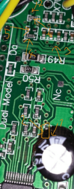
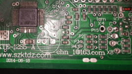
KT motor controllers -- Flexible OpenSource firmware for BMSBattery S/Kunteng KT motor controllers (0.25kW up to 5kW)

stancecoke said:
see my last edit, XS is AIN3 / Pin 19 on the 6FET, can you check this with your board and your XS1

regards
stancecoke

XS(1) to pin 19 is 0.9Mohm, looks like pin 19 is empty or going under the stm8 same on my bms battery 12fet

What is your voltage on x4? Have you tested with 12fet?
 
Can you find the Pin on the µC XS1 is connected to on your board?

honya96 said:
What is your voltage on x4? Have you tested with 12fet?
The voltage is 0V on the open X4 on the 6FET. I have no Kunteng 12FET. My 12FET is a Lishui....

regards
stancecoke
 
stancecoke said:
Can you find the Pin on the µC XS1 is connected to on your board?

honya96 said:
What is your voltage on x4? Have you tested with 12fet?
The voltage is 0V on the open X4 on the 6FET. I have no Kunteng 12FET. My 12FET is a Lishui....

regards
stancecoke

So, I will try to find any pin from AIN which is near 0v

I Can try on bmsbattery 12fet also so we may find one working for all. But it will take some time...

12fet board is simplier, see here. I wonder why its not connected all the same :roll:
https://drive.google.com/folderview?id=1MvJXz5b1dkX-HgpiXSiNgrJx5EFpt4z5

When I receive another 18fet I can teardown the first one a bit so I see the traces better. And take lots of photos....
 
honya96 said:
So, I will try to find any pin from AIN which is near 0v

there are no more possibilities, as we know the function of all AIN pins, see the schematic.

AI0,AI1,AI2 --> MOSFET low side
AI3 --> "XS" on 6FET
AI4 --> Throttle
AI5 --> Current Phase B
AI6 --> Battery current unfiltered
AI7 --> "X4"
AI8 --> Battery current filtered
AI9 --> Battery voltage

You can try to solder a wire directly to AI3 if you have a really steady hand :D But to be honest, I don't know if we get in trouble with using AI3, as there is the alternative function "TIM1_ETR" on this pin...

Perhaps we should use the existing wires for the linear regen: With pulling the brake lever slightly, use the normal throttle signal as linear regen signal. I don't know if you like this option to handle brake lever and throttle syncronously, it's easy to implement this in the code....

regards
stancecoke
 
Well, if its easy also I suggest doing the x4 regen as an option in java app + we will document somewhere how to get it working on 18fet and 12fet.

Brake signal + throttle regen can be option too but its not for me, I need left hand rear brake for doing wheelies. I am braking slightly while holding throttle so I have connected my lever brake signal in series and active only when both levers pushed.

Maybe adding a switch to deactivate brake signal while doing wheelies will be ok, so I can try it too if it will be just optional.
 
I checked the voltage on the open X4 at my 6FET again, there are 5V on it, too. With a ~10k Poti connected to gnd and +5V and the wiper to X4, it should work with the 18FET as well! Sorry for that confusion :oops:
It works with the poti, but it doesn't work with the thumbthrottle, as it can't pull the voltage down...
So i will try it on AIN3...

Potentiometers-Construction-768x404.png


regards
stancecoke
 
stancecoke said:
I checked the voltage on the open X4 at my 6FET again, there are 5V on it, too. With a ~10k Poti connected to gnd and +5V and the wiper to X4, it should work with the 18FET as well! Sorry for that confusion :oops:
It works with the poti, but it doesn't work with the thumbthrottle, as it can't pull the voltage down...
So i will try it on AIN3...
I wounder what are the differences on the S06ST torque sensor version, that has an input for throttle and another analog input for the "throttle" of the torque sensor........
 
@Stancecoke - try to get it working on X4 by easiest mod. possible so anyone can use it. AIN 3 looks empty on 12 and 18 fet and not everyone can solder to it.
 
My notes for S06ST torque sensor version:

The green wire from the torque-signal goes to the pad that's marked with "X4" on the circuit board (board revision KTE-6S3-B). The pad is connected via a RC-filter to pin 15, AIN7.

https://opensourceebikefirmware.bitbucket.io/development/Motor_controllers--BMSBattery_S_series--BMSBattery_S06S--S06ST_(torque_sensor_version).html
 
Yes, that's the configuration on my S06ST. The problem is, that the linear hall-sensor is not able to pull down the voltage, pehaps we can pull it down with a e.g. 1k resistor from X4 to gnd, and the Hall sensor is able to pull it up against this resistor, I'll try...
But maybe it is better to remove the pullup on the PCB....

regards
stancecoke
 
stancecoke said:
Yes, that's the configuration on my S06ST. The problem is, that the linear hall-sensor is not able to pull down the voltage, pehaps we can pull it down with a e.g. 1k resistor from X4 to gnd, and the Hall sensor is able to pull it up against this resistor, I'll try...
But maybe it is better to remove the pullup on the PCB....

regards
stancecoke

And maybe easy enough for everyone if we document which resistor it is. I will try it now.
 
Done, 0.047v at x4 with 18fet

1. Going to back side
2. Capacitor to ?
3. Back to front
4. 2.2K resistor in line to X4
5. Removed 2.2k to 5v
6. 100k to GND
7. Directly to X4
 

Attachments

  • 20180203_195526-274x693.png
    20180203_195526-274x693.png
    120.6 KB · Views: 2,263
honya96 said:
Done, 0.047v at x4 with 18fet

Great!! Then the thumbthrottle should work now as a "break pedal" :)

I tried a 1K as pulldown between X4 and gnd, this works also, but shifts the voltage level a little...
So the user can decide, which way he wants to go to use regen throttle...

Is the motor running with regen activated now?

regards
stancecoke
 
Done on 12fet also, arrow to which needs to be removed.

12fet has no 100k to GND so maybe better to remove on 18fet also.

Will try if the 18fet works now :)
 

Attachments

  • 20180203_201136-479x270.png
    20180203_201136-479x270.png
    93.4 KB · Views: 2,257
honya96 said:
12fet has no 100k to GND so maybe better to remove on 18fet also.

You can keep the 100k pulldown, it's good to have defined conditions, if x4 is left open!

regards
stancecoke
 
I received my new toys (didn't pay taxes):
1x S12S
2x S06S-BL (with Bluetooth)
1x torque sensor

Now my all my 3 ebikes have a torque sensor only and this means I will need to improve the torque sensor code as currently is far from perfect.

The Bluetooth version of S06S, because I hope to start play with it when the firmware is stable.

 
Anyone knows what is the max current of this controllers?

The LCD accepts 8 bits to represent the motor current and I think each bit represents 0.25A, meaning it would be 255 * 0.25 = 63.75 amps.

Should we consider the motor max current possible to be 63.75 amps?
 
casainho said:
Anyone knows what is the max current of this controllers?

The LCD accepts 8 bits to represent the motor current and I think each bit represents 0.25A, meaning it would be 255 * 0.25 = 63.75 amps.

Should we consider the motor max current possible to be 63.75 amps?

I have the S12SN controller from BMSB and a KT-LCD3 display. I don't think that my display shows Amps. It has a Watts display which I have seen show > 999W, and I believe goes up to 1999W.

HTH

Buk.
 
casainho said:
Should we consider the motor max current possible to be 63.75 amps?

I need more than 64A

24fet 70A stock is running that amperage continuosly cold to touch I guess..

Just shows 1999w on lcd.

I plan to run 100A+ with my 18fet.
 
honya96 said:
casainho said:
Should we consider the motor max current possible to be 63.75 amps?

I need more than 64A

24fet 70A stock is running that amperage continuosly cold to touch I guess..

Just shows 1999w on lcd.

I plan to run 100A+ with my 18fet.
So, I = P / U; 1999 / 48 = 41,645833333 <--- maybe the LCD was built to max of 48V and 40A. And maybe there are other versions of LCDs that can show higher power values... I guess a more powerful controller like 70A, can have double of shunts of the 40A (to handle max of 80A but can be programmed to handle the 70A) version and the LCD would just need to consider each bit = 0.5A instead of the 0.25A.

This are the shunts on the S12S 48V 40A controller I just received (didn't touch on the board, it is original):
 
casainho said:
The Bluetooth version of S06S, because I hope to start play with it when the firmware is stable.
Great! Can you check the name of the BT-module that is shown in connect screen of the Kunteng app? Here a screenshot with the Lishui BT-module (that doesn't work with the Kunteng App of course)

Thanks
stancecoke


Screenshot_20180206-203246.png
 
On My Android 7, it just shows sometimes a device (LanQianTech) and also on Linux I saw just for some seconds a device, sometimes, when I reset the S06S:


Trying on the Kunteng app, it does show another Bluetooth device but did never show the correct device.
And on Android, after clicked on the device, it seams to paired it however I never saw the LED of the module turned on.
I tested on 2 different S06S-BT controller and exchanging 3 different Bluetooth modules I have (1 extra from an old S06S-BT controller I bought before).
 
Does this mean, that you can't connect the app with the module?

The connection works for me, the Bluetooth Symbol is highlighted in blue colour in the upper right corner of the home screen. But there must be a handshake protocol, as the app sends "0x57" to the module in recent time intervals. If I send bytes from the module to the smartphone, they are received, but not processed.
Example from the log-file analysis by wireshark (btsnoop_hci.log created by the sniffing function in the developer tools of android):
Code:
host	controller	HCI_CMD	7	Sent Unknown 0xfd57

If you could log the communication when connecting the app with the module successfully, we could analyze, what's the right answer for the handshake...

regards
stancecoke
 

Attachments

  • Screenshot_20180206-212955.png
    Screenshot_20180206-212955.png
    47 KB · Views: 3,157
So finally I found a way to get it connecting very well, for that I had to increase the controller input voltage to at least 29V!! So I would say this Bluetooth modules only work for 36V input voltage even if they are connected to a S06S that says "24V/36V". I tested this controller and it works well with the LCD5 down to 20.5V input voltage (when the battery symbol is empty on LCD5).

Also without LCD5 connected, the Bluetooth module works -- I will later test if the controller can run the motor only with the Bluetooth module.
The Bluetooth module works even if the LCD5 is connected and working.
 
Back
Top