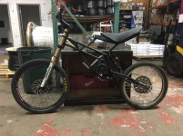
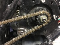
Kuberg Freerider Extended Swingarm Project

Aebrennan said:
I have 10 vids on YouTube under A e-bikes
Have over 500kms of testing completed
Never hear a “loud cry“only chain noise.

500kms of downhill? Link to a vid of a actual hill climb please?

Just because you rode 500kms now that means it can climb hills good??

Every video of the sur ron sounds very loud and whiny, that again is my opinion based off youtube video sound.
 
The thread is about your build not the Sur-ron.
My videos are linked on the appropriate threads and YouTube as mentioned.
My comment was regarding your “opinions” based on videos, but no links to the mentioned videos.
Thanks for your opinions.
 
Well either way ive watched your vids and the bike looks like lots of fun. I just call it like i see it
 
jonnydrive said:
Is not my idea :) I read it somewhere in Cyclone 3k mega-thread.
For combination Kelly Controller + Cyclone, it is suggested to use 12volt for power the hall sensors instead of a traditional 5v.

Revolt use SS411/41F that from datasheet support this power: 5V/9V/ 12V/15V/18V/24V.

My bet: more voltage in hall sensors is equivalent to a widest signal range, maybe it can overhang the white noise, parassite currents, etc....
In fact, my controller faults only when high amperage is required, that match with a stronger magnetic field generated by the engine. Can be this interference the cause of fault in the sensors? I am no sure.

It can worth a try....as soon I can get my hands on my motorcycle I will do it.

I'm going to keep you updated.

Does anyone know if the ground on the hall sensors has to be common with the controller battery input ground? Or can you run your hall sensors off a 9volt battery completely separate and be fine with the signal they output?

Thanks in advance, still pondering this 12v to halls things
 
skeetab5780 said:
Does anyone know if the ground on the hall sensors has to be common with the controller battery input ground? Or can you run your hall sensors off a 9volt battery completely separate and be fine with the signal they output?

Thanks in advance, still pondering this 12v to halls things

Each signal needs a reference, so you must connect the ground. I am not sure if the ground from the hall wires is same as battery -, but i believe so (if your multimeter beeps than it is same).
 
madin88 said:
skeetab5780 said:
Does anyone know if the ground on the hall sensors has to be common with the controller battery input ground? Or can you run your hall sensors off a 9volt battery completely separate and be fine with the signal they output?

Thanks in advance, still pondering this 12v to halls things

Each signal needs a reference, so you must connect the ground. I am not sure if the ground from the hall wires is same as battery -, but i believe so (if your multimeter beeps than it is same).

Yes they have continuity unfortunately, just tested batt ground to hall ground

so I will have to attempt running it off the 12vdc output from the controller. I wanted to try and run it off a small separate battery pack at like 8 or 9v but not going to happen.
 
Hi Skeet,
If there is continuity between battery negative and hall sensor negative, that is good.. connect the negative of the 9V battery to either the battery negative or the hall negative, and the +9V of the battery to the hall sensor supply Positive. (You will have to disconnect the hall sensor + from the controller before connecting the battery +.)

I don't know the max voltage your hall sensors are rated to, but if it is higher than 9V they should be ok.

I also do not know what the effect of the raised voltage of the hall signal will be on the controller, but I doubt 9V will fry anything..

There has been a bit of evidence scattered around a few different threads on ES that faulty or missing signals from hall sensors are known to occur, and some problems have been solved by relocating hall sensors, replacing with new ones or changing to a different type.

If you know anyone with an oscilloscope (preferably with 3 or more channels) and you can rotate the motor at a steady speed (using a big, slow drill or lathe etc) you could apply + and - power to the halls and connect the oscilloscope to the hall outputs and see whether:
- the output voltages are regular or variable;
- the switching occurs quickly (steep leading edge to the signal on the screen) every time; and
- the spacing between the hall output signals is regular (wave forms spaced evenly across the screen).

Any irregularity would indicate poor performance of the hall sensors.. the wave forms must be even height, regularly spaced and fast switching every time. Missing or irregular signals would make it very hard for the controller to do its job well.

You could test at 5V and at 9V and see if there is any difference (other than the output voltage of course).

There are others here on ES with a lot more knowledge and experience than me who might like to comment here...

I believe that accumulating more knowledge about Hall sensor performance, testing methods, problems and solutions would be useful. Maybe a thread dedicated to Hall sensors would be good. (Thinks to self.. maybe I should have looked in other sections of ES.. there may already be a thread somewhere??)

Definitely interested to see what you come up with. Good luck.

Dave
 
Hi guys,
I contacted Kelly (Fany) for other problems with the controller, but..the interesting thinks is what I am quoting:

"We need to use pin11 (12v) to power hall sensors of Cyclone motor instead of pin5 (5v)."
and
"As of KBS-X controller,it is better to use pin11 to power hall sensors of Cyclone motor."

Sincerely I do not know if it is worth also for other troubled hall sensor engine.

I made a lot of tries with home-made oscilloscope try to understand if the halls are good, but when you put a lot of kw in the engine thinks is quite different compared to a work bench testing.
 
Thats wierd they are saying to use 12v pin out on both kbs and kls series...my motor only has this issue with the kls.

Makes me wonder if its the same issue...afterall im not using a cyclone motor. Im still going to have to try it. Im just going to be mad if i ruin my halls on my fav motor
 
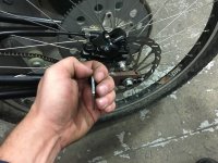
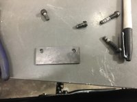
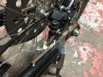
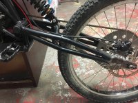
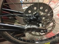
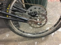
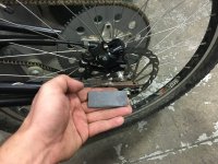
Had a few minutes to get some work in so started working on a rear disc brake bracket for the bike finally! at first I grabbed a piece of steel and worked on it for about 20 minutes cutting and filing it to size...then I realized it was way to thick of a steel bar and it was oversized, so I started over. Have it pretty much done just need to tack it on the frame
IMG_1893.JPG
IMG_1899.JPG
IMG_1900.JPG
IMG_1901.JPG
 
About time you got some rear brakes on that thing! :D

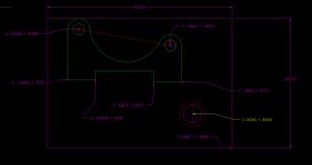
If this helps at all here is the dimensions on the jig plate I use to position the brake mount on the genesis swing arms. You can lay these dimensions out on a plate and drill the 2 brake holes as well as the axle hole. Install the jig on the axle and use washers to space the brake bracket to suit your rotor position axially. Since its relative to the axle you can clock it in any position and grind the caliper mount plate to sit on any shape swing-arm.
brake dimensions.png

I can also email you a cad file that you could print at 1:1 on some card stock to use as a jig if you need it.

Probably doesn't need to be that precise but it seemed like a waste of a perfectly good file sitting here on my hard drive.

Attached is also a PDF you can print at actual size and use as a jig. In the past Iv'e just used photo mount glue to stick 1:1 print outs onto the material and just grind and drill to created complex shapes at home without fancy tools.
 

Attachments

  • Scan of bracket.pdf
    983 KB · Views: 122
Awesome Tyvm Dan! I will save it so its taking up space on both our PC's :)

I never get to see my brother so when I can get him around maybe this weekend he will weld the two thing I want welded

first thing is I want one more motor support tab welded to the frame
and secondly the rear caliper bracket
 
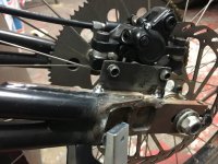
So we tacked the disc caliper adaptor in place and then we took the rear wheel off to get a good bead front and back, my brother wasn't proud of his weld on this piece since he is a perfectionist! I said IDC
IMG_1904.JPG
IMG_1905.JPG

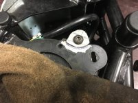
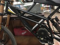
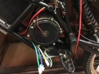
Then while letting the rear end cool down before putting the wheel back on we also took this chance to make another motor bracket for the LRHDD motor. When I lined it up where I wanted it the two larger bolts ended up being useless...this could have been my fault but either way we welded a quick tab in place to support the torque better.

IMG_1909.JPG
Watch vid to see pro welds

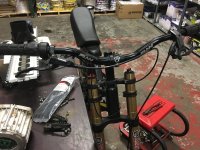
Also put a slightly shorter stem on the bike to make it not look so akward...
IMG_1912.JPG
 
Last edited:
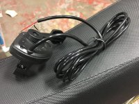
So since I was putting a brake lever on the right side of my bars I figured I would attempt to put a new thumb throttle on similar to the one on my Apollo dirt bike, but the second I tried to line everything up and use it I hated it. I ended up putting the half twist back on for now, but I think I will change to the older gray short thumb throttle again later...such a pain to find the perfect throttle for every different bike and its ride style.
IMG_1914.JPG
Loosely fit the brake caliper on place so I could run the hydro lines and zip tie them into submission, they never like to bend where you want them they just do their own thing!
IMG_1915.JPG
I just ran the lines up the frame for now not sure if it will stay this way since this one is a bit longer than it needs to be...go figure the front is too short this one is too long!!
IMG_1916.JPG
I ended up having to change out a few of the bolts and washers to line it up perfectly, here is the end result. My brother is not happy with his weld but I told him I don't care much
IMG_1917.JPG
Cable is a bit long but will work fine for now until I get a barb/hose kit
IMG_1918.JPG
 
Is that a personal thing? Rear brake lever on right and front on left, or is that how bicycles are setup in the states? Have always run front brake lever on right and Rear on left. Seems more natural especially when swapping between bicycles and motorbikes.
 
Its just how bicycles are setup around here in new England anyway...Its what im used too even though motorcycles and dirt bikes have front on the right and rear on the foot. I like the bicycle way, the only downfall is its harder for learning wheelies with the rear on the throttle side.
 
So since there are two solutions available to get my controller and motor combo to work properly. A few threads have popped up around the forums about this.

The first solution is the try diodes between the motor and controller halls, this is what I would like to try first...but I need one more diode

The second would be to try and run the halls off 12v output of the controller instead of the 5v standard, this worries me since I would hate to fry my halls for something so stupid, but most data sheets are claiming hall sensors can take upwards of 15v without damage, im not sure which are in the LRHDD motor

Either way I am attempting to put the bike back together with the KLS controller now. Hopefully we can sort the issue out later on
IMG_1919.JPG
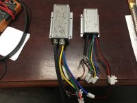
This tiny little controller is really really awesome, I will likely use it on the Vector lite now to run higher voltage. But it is too small for this bike
IMG_1920.JPG
KBX 55a Vs KLS 80a
IMG_1921.JPG
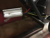
Nevermind the 80a KLS fits perfectly into the frame and looks beefier!
IMG_1922.JPG
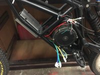
Here is another shot of the new motor mount, it makes me feel so much safer about the mounting, the LRHDD bolt pattern is in a much smaller diameter than the motor Kuberg must actually use...but I made it work obviously
IMG_1923.JPG
 
Mad Matt said:
Is that a personal thing? Rear brake lever on right and front on left, or is that how bicycles are setup in the states? Have always run front brake lever on right and Rear on left. Seems more natural especially when swapping between bicycles and motorbikes.

Yeah every single bicycle I've had is set up this way, it gets ingrained in your head and is actually pretty good for ebikes if you just have a front ebrake lever-it's like a clutch to kill power when needed. When I jump on a motorcycle I automatically revert to shifting on left side, braking on right side.
 
skeetab5780 said:
Its just how bicycles are setup around here in new England anyway...Its what im used too even though motorcycles and dirt bikes have front on the right and rear on the foot. I like the bicycle way, the only downfall is its harder for learning wheelies with the rear on the throttle side.

How true! doing wheelies is really hard if rear brake and throttle are on the same side.

I have a question: Whats the axle diameter of this motor and where can i buy such sprockets which fit on this motor?
 
madin88 said:
skeetab5780 said:
Its just how bicycles are setup around here in new England anyway...Its what im used too even though motorcycles and dirt bikes have front on the right and rear on the foot. I like the bicycle way, the only downfall is its harder for learning wheelies with the rear on the throttle side.

How true! doing wheelies is really hard if rear brake and throttle are on the same side.

I have a question: Whats the axle diameter of this motor and where can i buy such sprockets which fit on this motor?

Madin I don't have the specs of the motor on hand, but I purchased it from forum member lightingrods and its the best. it has a smaller diameter shaft but he includes a aluminum slipover sleeve and the 219 sprockets in all sizes. it allows for quite a bit of adjustments/configurations
 
OK SO JUST AN UPDATE...I SPENT THE DAY YESTERDAY PUTTING THE KLS CONTROLLER BACK ON THE BIKE WITH MY NEW BATTERY AND I PUT PIN#11 (12 VOLTS PLUS) TO MY HALL SENSORS IN ATTEMPT TO FIX THE SIGNAL LOSS ISSUE BUT IT DIDNT DO ANYTHING AT ALL, if anything its the exact same if not worse (even more dangerous to control/stop) this fix was for cyclone motors with Kelly controllers and it does nothing for the LRHDD I use.

So there is one useless option out of the way...now I need to find a electronics store around that has a diode for sale so I can try the other so called proven solution!

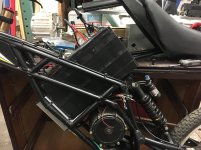
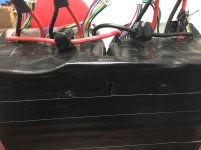
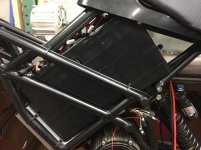
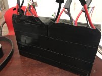
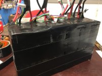
Taped my packs up to get them in the Kuberg
IMG_1925.JPG
IMG_1926.JPG
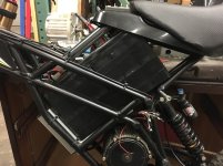
Sized it up real quick to see if it will fit, it is so extremely tight!
IMG_1927.JPG
I had to squish the pack about 1/4 inch to lock the subframe into place...hopefully it doesn't blow up!
IMG_1928.JPG
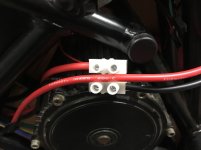
cut my Polaris connectors to let me parallel my packs how I needed
IMG_1929.JPG
locked it in place, and protected any wiring that could possibly short
IMG_1930.JPG
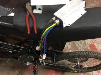
Started wiring the KLS controller yet again...this is getting old
IMG_1931.JPG
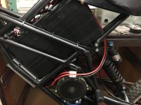
Routed my new battery 10awg 200deg wires to the controller, they are slightly longer now due to the 24ah pack. You can just barely see my charging xt60 under the seat
IMG_1934.JPG
Brought the positive wire which is the last one to connect. I temped it out while trying to program the bike and the motor is completely dangerous and uncontrollable now...hopefull the diode fix works next!
IMG_1935.JPG
 
Well I found a 20x pack on the 1n5404 diodes for $3 bucks

so I will find out soon if this is a good solution or not, if this does not work im buying a new KBS controller and out goes $200 wasted!
 
Got the Diodes in the mail today, hopefully I can try to solder them in tomorrow if I get time

Im very curious to see if this solves the problem...at this point Im skeptical but Im willing to give it a shot before I spend another $200 on a KBS controller and try to sell this one used.
 
How or where do you install the diodes exactly?
 
Back
Top