KT motor controllers -- Flexible OpenSource firmware for BMSBattery S/Kunteng KT motor controllers (0.25kW up to 5kW)

honya96 said:
lizardmech said:
Basically you have to configure any software based on the mV/A value but keep in mind the sensor is only accurate within its listed current rating.

@casainho - So if we you use the value from sensor, we need parallel resistor as you said.

The resistor hack works, however you need a power resistor with that can handle quite a bit of heat depending on how much current you want it to take. Accuracy is also degraded due to temperature impacting resistance. The ACS + resistor hack use to be popular because there was no compact SMD ACS sensor for higher currents, recently they released a small SMD ACS sensor with 100V isolation and +/- 100A sense ranges so its no longer needed.
 
lizardmech said:
The resistor hack works, however you need a power resistor with that can handle quite a bit of heat depending on how much current you want it to take. Accuracy is also degraded due to temperature impacting resistance.

It will take almost no voltage drop so kind of any smd near zero Ohm should do the job.

100A is good enough for stock 6fet for sure (easier to add resistor still..), but I have one modified and want to try 72v/60A,120pA :twisted: (once the phase current limiting is ready)
 
honya96 said:
100A is good enough for stock 6fet for sure (easier to add resistor still..), but I have one modified and want to try 72v/60A,120pA :twisted: (once the phase current limiting is ready)
The phase current limit is now done, as I explained in my last post.

Now I want to try it on a real ride and I don't know which should be the limit for motor phase current, for this S06S 6 mosfets controller, that says max of 15 amps on the specification - I guess 15 amps is not the phase current as this seems a very low value, I think 15 amps are the battery current. Anyone knows which value should I configure as max motor phase current value??
 
casainho said:
honya96 said:
100A is good enough for stock 6fet for sure (easier to add resistor still..), but I have one modified and want to try 72v/60A,120pA :twisted: (once the phase current limiting is ready)
The phase current limit is now done, as I explained in my last post.

Now I want to try it on a real ride and I don't know which should be the limit for motor phase current, for this S06S 6 mosfets controller, that says max of 15 amps on the specification - I guess 15 amps is not the phase current as this seems a very low value, I think 15 amps are the battery current. Anyone knows which value should I configure as max motor phase current value??
Almost certain it will be 15A motor phase limit, its rare to see high side DC bus current sense used for controller rating. 36V x 15A = 500 watts, similar to the hoverboard motors, I found those saturate at around 20A. For a 250watt controller 15A can quite easily be the absolute max motor current. If the mosfets can survive the current you will still have to check the voltages on the high side mosfet drain are staying well away from their maximum voltage, because the controller only has bulk capacitance quite a way from some of the mosfets high currents can create a situation where inductance results in voltage overshooting as the top mosfet turns off.
 
lizardmech said:
Almost certain it will be 15A motor phase limit, its rare to see high side DC bus current sense used for controller rating. 36V x 15A = 500 watts, similar to the hoverboard motors, I found those saturate at around 20A. For a 250watt controller 15A can quite easily be the absolute max motor current. If the mosfets can survive the current you will still have to check the voltages on the high side mosfet drain are staying well away from their maximum voltage, because the controller only has bulk capacitance quite a way from some of the mosfets high currents can create a situation where inductance results in voltage overshooting as the top mosfet turns off.

the 'good' thing about these cheap controllers is that they switch quite slow. so less overshoot effects (but more switching losses i.e. heat)
 
honya96 said:
lizardmech said:
The resistor hack works, however you need a power resistor with that can handle quite a bit of heat depending on how much current you want it to take. Accuracy is also degraded due to temperature impacting resistance.

It will take almost no voltage drop so kind of any smd near zero Ohm should do the job.

not true. lets say you want to double the amperage. so half of the current is flowing through the resistor. the resistor needs to be 1.2mR (because the element in the ACS712 is also 1.2mR). at 30A that's 1.08W (30*30*0.0012)
 
nieles said:
honya96 said:
lizardmech said:
The resistor hack works, however you need a power resistor with that can handle quite a bit of heat depending on how much current you want it to take. Accuracy is also degraded due to temperature impacting resistance.

It will take almost no voltage drop so kind of any smd near zero Ohm should do the job.

not true. lets say you want to double the amperage. so half of the current is flowing through the resistor. the resistor needs to be 1.2mR (because the element in the ACS712 is also 1.2mR). at 30A that's 1.08W (30*30*0.0012)

Well, I dont consider 1w to be quite a bit of heat, its only for a second at startup or uphill 5km/h full throttle, and we dont need to double it.
 
lizardmech said:
Almost certain it will be 15A motor phase limit
Can bet anything that its DC limit, actually I know it for sure.

@Casainho - look at your mosfet specs, thats the limit, but it will be a huge kick from standstill even at 15A DC, you dont need that. STP80NF70 is 98A,

Try 30A phase first with throttle, then you can adjust to get the start torque you expect when pulling full throttle fast.
 
casainho said:
...
3. The mathematical model says that: battery current = duty_cycle * motor phase current. As the duty_cycle was 33%, so the motor phase current should be (battery current / 0.33) = 2.5/0.33 = 7.6 amps <--- the measured values seems to be inline with the mathematical model.

To be honest, I don't understand that approach.
If it is as easy as battery current = duty_cycle * motor phase current there is no need to measure the phase current, we can just calculate it.

regards
stancecoke
 
stancecoke said:
To be honest, I don't understand that approach.
If it is as easy as battery current = duty_cycle * motor phase current there is no need to measure the phase current, we can just calculate it.

regards
stancecoke
But maybe its true, FOC controllers need it to run FOC, we dont.
 
honya96 said:
lizardmech said:
Almost certain it will be 15A motor phase limit
Can bet anything that its DC limit, actually I know it for sure.

@Casainho - look at your mosfet specs, thats the limit, but it will be a huge kick from standstill even at 15A DC, you dont need that. STP80NF70 is 98A,

Try 30A phase first with throttle, then you can adjust to get the start torque you expect when pulling full throttle fast.
15A DC link limit is much too high, that's 50A+ at 20% duty cycle, there's a decent amount of headroom on those fet voltage ratings between that and the slow switching it's probably fine, 30A is should be good for small bursts but will probably burn if continuous. Small 250W motors will saturate quickly, once the stator reaches the maximum flux it can handle additional current no longer generates torque. A 36V or 24V motor rated for 250watts should max out around 15A so a more powerful motor may be needed to test it well.
 
stancecoke said:
casainho said:
...
3. The mathematical model says that: battery current = duty_cycle * motor phase current. As the duty_cycle was 33%, so the motor phase current should be (battery current / 0.33) = 2.5/0.33 = 7.6 amps <--- the measured values seems to be inline with the mathematical model.

To be honest, I don't understand that approach.
If it is as easy as battery current = duty_cycle * motor phase current there is no need to measure the phase current, we can just calculate it.
That is a good question that I did to myself. Since "battery current" uses a low pass filter on the circuit and adds a considerable delay, I think we can't use it to read each PWM cycle and protect the fets due to high current value (motor phase current). Maybe this is what is mentioned on the app note:
Any effort to compensate the average DC link current data with the duty cycle to obtain average phase current will be impaired by a filter time constant, rendering this option ineffective.

So, current code should be good to protect powerful fast motors as Onya is being asking, I hope.
 
Alert!!

Some S06S controllers has a phase B current sensor ACS712 instead of ACS711. The ACS712 output voltage for 0 amps is 2V and not 2.5V as on ACS712 and this means the "very low resolution FOC" code must be adapted for this difference -- my current code:

main.h:
Code:
//#define ADC_PHASE_B_CURRENT_ZERO_AMPS_FOC_MAX 127 // for phase B current sensor that outputs 2.5V at zero amps (ACS711)
//#define ADC_PHASE_B_CURRENT_ZERO_AMPS_FOC_MIN 125 // for phase B current sensor that outputs 2.5V at zero amps (ACS711)
#define ADC_PHASE_B_CURRENT_ZERO_AMPS_FOC_MAX 102 // for phase B current sensor that outputs 2.5V at zero amps (ACS712)
#define ADC_PHASE_B_CURRENT_ZERO_AMPS_FOC_MIN 100 // for phase B current sensor that outputs 2.5V at zero amps (ACS712)

motor.c
Code:
  ui8_motor_rotor_angle += ((uint8_t) FOC_READ_ID_CURRENT_OFFSET);
  // make sure we just execute one time per ERPS, so use the flag ui8_flag_foc_read_id_current
  if ((ui8_motor_rotor_angle >= ((uint8_t) FOC_READ_ID_CURRENT_ANGLE_ADJUST)) && (ui8_flag_foc_read_id_current))
  {
    ui8_flag_foc_read_id_current = 0;

    // minimum speed to do FOC
    if (ui16_motor_speed_erps > MOTOR_ROTOR_ERPS_START_INTERPOLATION_60_DEGREES)
    {
      // read here the phase B current: FOC Id current
      ui8_adc_id_current = UI8_ADC_PHASE_B_CURRENT;

      if (ui8_adc_id_current > ADC_PHASE_B_CURRENT_ZERO_AMPS_FOC_MAX) { ui8_angle_correction++; }
      else if (ui8_adc_id_current < ADC_PHASE_B_CURRENT_ZERO_AMPS_FOC_MIN) { ui8_angle_correction--; }
    }
  }
 
casainho said:
So, current code should be good to protect powerful fast motors as Onya is being asking, I hope.

So how is that "phase current limiting" implemented now? If its the simple calculation and there is a delay in dcA there will be delay in limiting..?

Can we get rid of that low pass filter? Optional: stock or without?

My 6fet has Cs712T so its wrong? Means just that I need to use different FOC angle value right? Because it worked ok after setting..
 
honya96 said:
casainho said:
So, current code should be good to protect powerful fast motors as Onya is being asking, I hope.

So how is that "phase current limiting" implemented now? If its the simple calculation and there is a delay in dcA there will be delay in limiting..?

Can we get rid of that low pass filter? Optional: stock or without?

My 6fet has Cs712T so its wrong? Means just that I need to use different FOC angle value right? Because it worked ok after setting..
The S06S has 2 signals from shunt, one filtered (battery current) and other not filtered (motor phase current). I wrote before, about battery current were I thought it was motor current -- please see: https://opensourceebikefirmware.bitbucket.io/development/Datasheets_and_application_notes--Endless-sphere.com_forum_messages--2017.09.19_-_measuring_motor_current.html

And now I wrote on how to measure motor phase current: https://opensourceebikefirmware.bitbucket.io/development/heets_and_application_notes--Endless-sphere.com_forum_messages--2018.02.20_-_Reading_motor_phase_current_from_the_DC_link_current_(shunt).html

The code is not clean yet, it is not on master branch but on other. I just did a ride and it went well, as expected.

Although FOC works considering that 2.5V not real value, it should run motor not efficient.

When I have the new code clean and ready, it will also have a #define to choose ACS711 or ACS712.
Also, I think signal for battery current and motor phase current, are different, as I did measured before 1.59V with 0 amps but on this "old" controller I did measure 1.5V with 0 amps....
 
casainho said:
The S06S has 2 signals from shunt, one filtered (battery current) and other not filtered (motor phase current).

I'm not happy with this wording at all. It's not the real battery current, as the shunt is placed between the gnd of the MOSFETs and the big capacitors. And it's not the real phase current, as the shunt is not placed in the phase line. We should consider this to avoid confusion....

there are 6 pages of discussion concerning motor current and phase current on the vedder.se forum (VESC) :wink:

regards
stancecoke
 
stancecoke said:
casainho said:
The S06S has 2 signals from shunt, one filtered (battery current) and other not filtered (motor phase current).

I'm not happy with this wording at all. It's not the real battery current, as the shunt is placed between the gnd of the MOSFETs and the big capacitors. And it's not the real phase current, as the shunt is not placed in the phase line. We should consider this to avoid confusion....
I don't know which words to use. Can you please suggest? I will soon (in next hours) clean the code and I should use correct variable names, to make clear for anyone that reads the code.
 
I've no suggestion, as I'm struggling myself at this topic.
A quite interesting plot from the discussion linked above:
file.php


As you can see, the current in one phase can be quite high, while the current in the other two phases is negative... So I don't understand the simple formula battery current = Duty Cycle * phase current

With block commutation (6Step), where always one phase is floating, the formula may be OK...

regards
stancecoke
 
stancecoke said:
casainho said:
The S06S has 2 signals from shunt, one filtered (battery current) and other not filtered (motor phase current).

I'm not happy with this wording at all. It's not the real battery current, as the shunt is placed between the gnd of the MOSFETs and the big capacitors. And it's not the real phase current, as the shunt is not placed in the phase line. We should consider this to avoid confusion....

there are 6 pages of discussion concerning motor current and phase current on the vedder.se forum (VESC) :wink:

regards
stancecoke

It depends where the current sense is placed, if its between the source of all 3 low side mosfets tied together and ground then a single shunt can measure the total motor current, if you have only one individual low side source connected you could still measure the current however only when that specific mosfet is in use, you would miss over current or shorts when the other two are being used.

On hardware like the VESC 4 with twin low side current sense you can do additional things such as motor detection, twin low side current sense still has one significant weakness, it can't detect over current or shorts on the mosfet without a sensor. The DRV chip on the VESC has some circuits to try and detect this if it happens. All low side current sense options have the limitation that they can only measure motor current when the low side mosfets are conducting.

With in phase current sense you should be able to detect everything with only two sensors and have more opportunities to sample motor current as it's possible to measure it when both high and low side mosfets are conducting. Additionally any over current issue or short will show up on in phase current sense. 2 in phase sense vs 3 in phase is less clear, in theory 2 should be the same but using all 3 might allow slightly less noisy data, I haven't seen a detailed comparison anywhere.
 
So I want to implement limit max motor and battery currents. Do you guys know if I should do also limit battery and motor max currents? -- because before I were just limiting battery current for regen...
 
casainho said:
So I want to implement limit max motor and battery currents. Do you guys know if I should do also limit battery and motor max currents? -- because before I were just limiting battery current for regen...

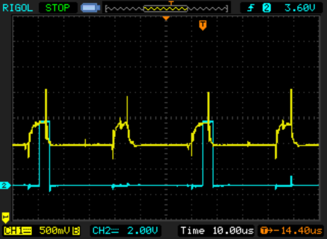
After last lizardmech's post I wonder how does the ouput of the shunt look like, will get an osciloscope. Suggestions? Would like USB to PC app only.

Anyway to your question since until now you was succesfully limiting DC - battery current to set value, can stay same for now. Is it using filtered value or not? If filtered, it should use not filtered and filter by fw so theres no delay at start..?

Phase current - I dont know which way you want

The simple calculation phase/pwm=battery
or some calculation from 1 phase hall (not good enough)

Or maybe shunt reads phase current combined and we were limiting just phase current? (I dont believe that beacuse starting torque will be low)

Geoft has probably tested more than me so he can tell and say what Amp setting he used vs stock

Or maybe stock fw reads shunt phase current combined and calculates battery current the simple way, but then no way battery current limit can work now since you wrote the code so you know what it does?

I am thinking where is the change happening from 10 battery amps to 30 phase amps, if 30A is top of sine wave, possibly capacitors taking care of that, so when shunt is between caps and fets it sees phase current combined then? Not battery current that should be measured before capacitors?

I see a lot of good info in lizardmech's post, maybe he can help.

Am I wrong that everytime there is a current to motor it goes through one low side and one high side mosfet? :shock: If Iam right then lizardmech is wrong in that part about combined phase current not being able to detect short (overcurrent in normal use)

All above just my assumtions, not knowlege.

Hope it hepls and I would like someone to review and discuss.

Edit: if stock fw limits phase current combined only, I lived in a lie :D will test well tomorow
 
I already took the shunt oscilloscope screenshots: https://opensourceebikefirmware.bitbucket.io/development/heets_and_application_notes--Endless-sphere.com_forum_messages--2018.02.20_-_Reading_motor_phase_current_from_the_DC_link_current_(shunt).html

But yes, the yellow line is the voltage on shunt and amplified by the opamp:
118-3.png


For now, I will stick with the information from ST: AN2267 - Implementation of current regulator for BLDC motor control with ST7FMC.pdf and I will consider that I read battery and motor currents.
 
So yes, both regen motor and battery currents should be controlled. Motor regen current depends more on hardware so it probably is the same value as motor current. Battery and battery regen currents are different, because batteries charge at lower rates.

Here is a VESC configuration tool showing all this: http://www.electric-skateboard.builders/t/vesc-faq-regen-braking-configuration-bldc-tool-brake-force/353

 
casainho said:
Motor regen current depends more on hardware so it probably is the same value as motor current. Battery and battery regen currents are different, because batteries charge at lower rates.

Here is a VESC configuration tool

My smaller "big" bike can take 50A battery regen current if overvoltage limited... just saying

VESC config looks good, would love to have same with kunteng :) and I hope the way you are implementing will do the job for this summer.

Edit: absolute max value seems unnecesary, the one set should be absolute max.
 
honya96 said:
My smaller "big" bike can take 50A battery regen current if overvoltage limited... just saying

VESC config looks good, would love to have same with kunteng :) and I hope the way you are implementing will do the job for this summer.
At slow loop 10Hz, using PI controller, only motor phase current is being controlled for the value defined by the rider, using for instance, the throttle.

The max values limits are controlled every PWM cycle. I think is easy to understand my implementation, because it seems "quick and dirty". And as you can see, controlling battery overvoltage is done:

Code:
  /****************************************************************************/
  // PWM duty_cycle controller:
  // - limit battery overvoltage
  // - limit battery max current
  // - limit motor max current
  // - limit battery max regen current
  // - limit motor max regen current
  // - ramp up/down PWM duty_cycle value

  if ((UI8_ADC_BATTERY_CURRENT > ui8_adc_target_battery_current_max) || // battery max current, reduce duty_cycle
      (ui8_adc_motor_current > ui8_adc_target_motor_current_max)) // motor max current, reduce duty_cycle
  {
    if (ui8_duty_cycle > 0)
    {
      ui8_duty_cycle--;
    }
  }
  // verify if there is regen current > 0 (if there is happening regen) and
  // if battery voltage is over or equal to absolute battery max voltage, and if so
  // reduce regen current -- the idea is to avoid overcharge the battery
  else if (((ui8_adc_motor_current < ui8_adc_motor_current_offset) &&
      (UI8_ADC_BATTERY_VOLTAGE >= ((uint8_t) ADC_BATTERY_VOLTAGE_MAX))) ||
      // verify battery max regen current limit
      (ui8_adc_battery_current < ui8_adc_target_battery_regen_current_max) ||
      // verify motor max regen current limit
      (ui8_adc_motor_current < ui8_adc_target_motor_regen_current_max))

  {
    if (ui8_duty_cycle < 255)
    {
      ui8_duty_cycle++;
    }
  }
  else // nothing to limit, so, adjust duty_cycle to duty_cycle_target, including ramping
  {
    if (ui8_duty_cycle_target > ui8_duty_cycle)
    {
      if (ui16_counter_duty_cycle_ramp_up++ >= ui16_duty_cycle_ramp_up_inverse_step)
      {
	ui16_counter_duty_cycle_ramp_up = 0;
	ui8_duty_cycle++;
      }
    }
    else if (ui8_duty_cycle_target < ui8_duty_cycle)
    {
      if (ui16_counter_duty_cycle_ramp_down++ >= ui16_duty_cycle_ramp_down_inverse_step)
      {
	ui16_counter_duty_cycle_ramp_down = 0;
	ui8_duty_cycle--;
      }
    }
  }
  /****************************************************************************/
 
Back
Top