Converting a hubmotor to a middrivemotor

Mind sharing where you found such an awesome deal on that BPM? Inquiring minds want to know.

Also, is this the staton inc. adaptor you're talking about?

http://www.staton-inc.com/store/index.php?p=product&id=1931
 
I found it trawling alibaba and after a considerable amount of back and forth communication me and the chinese sales guy finally know what we are talking about and understand each other as to the exact specifications I wanted, they sell front, rear freewheel threaded or cassett versions of the BPM with 4 different winding speeds the freewheel and front mount ones have a disk interface and are the same price at $86 and the cassett version $96 usd plus freight, I dont know what it would be to BC

they sell many different windings

figures are for no load speed at 36v, these are the four fastest windings available they may do slower ones as well but I only have the data for the fast ones (0.5mm lams)
first number is number of strands wound second is number of turns

winding rpm speed on a 26"wheel (kmh)
9x11t 260 32
10x10t 280 35
11x9t 305 38
12x8t 336 42

they also do the swx(o,f,h,g) motors 250 or 350w with windings from 7t (420rpm) counting up to 15t (213rpm) for the 250 with weaker magnets and the 350w with stronger magnets from 10t (288rpm) counting up to 14t (188rpm)
the smaller motors have the 0.35mm lams the bpm has 0.5mm lams

the bpm can be found here
https://www.alibaba.com/product-detail/Greenpedel-36v-48V-BPM-500w-brushless_60672455555.html?spm=a2700.7724838.2017005.2.2909385aq73BdM

Talk to Jack Jiang he was very helpful with photos and specifications, his english is not the greatest but we managed to get on the same page fairly quickly. if you hold off any further purchases from this seller until I have the one he is sending in hand I will pull it down and post pics and measurements, it should arrive two to threeweeks.
 
yes that is the staton adapter i was talking about , they also do it in 5/8 and 3/4 shaft size my preference is to make a rotor holder like crossbreak did and a custom shaft with keyways not flat sides.
 
thx for that info. so can this seller do an 8T? that would be great. I never got an 8T. 10t was the fastest i was able to order. A 9T would still be worth converting for a 48V setup. I have lasered BB brackets for this conversion left i can send you. I still have an 11T BPM collecting dust which would be still good for a 72V drive but had no time yet to convert that one. Sadly i have no M30x1 freewheel adapter parts left anymore...all sold. hope you have a lathe to make the freewheel adapter? my lathe cant do this thread yet, need to retrefit but also little time for that..
 
mechhead said:
yes that is the staton adapter i was talking about , they also do it in 5/8 and 3/4 shaft size my preference is to make a rotor holder like crossbreak did and a custom shaft with keyways not flat sides.

ok with a custom shaft you will stillt need an m30x1 adapter or something that takes a small freewheel. the shaft that comes with this motor isnt that bad, i dont know if its worth to swap, depends on the tools you have access to
 
HIi Crossbreak, the one i have ordered is an 8t the naming system this factory uses is number of strands, number of turns
for example 12x8t is 12 strand winding of 8 turns, this is the one I have ordered.

I have access to a lathe and milling machine.

i was thinking to copy your design with the rotor carrier seperated from the shaft and either lathe the shaft down to pass through the rotor holder or if its the single keyway shaft fabricate a whole new shaft with key ways and a keyway out put instead of the double flats. The staton adapter looks good for this it takes a 1.37x24 tpi thread not sure how this converts to metric, but acs freewheels are available in this thread.

I did some calcs and came up with a 56t chainring pedal to 17t freewheel with 19t motor output sproket, sunrace 11-40t 8 speed cassett for maximum torque band at speeds of 70 to 100 pedal rpm and wheel speeds of 1st gear 15kmh @peak torque 20kmh no load and 28 kmh T peak to 38kmh at no load speed. Based on peak torque at 75% noload speed. based on your thoughts of no more than 1.5x bat to phase amp ratio.

I like the look of the BB mounts you had laser cut, can you post some photos of the brackets you've got and we can work out something for you in return if I like them and they will fit my frame.

I may be off the net for a few days as we are moving house and it will take time to get the net on at the new place.

it will be interesting to see how the vesc-x handles this motor, when i get it to self test and probe the motor for parameters I will post all the motor self test specs, this controller is clever as it pings the motor with pulses to assess its properties ,inductance r and l values and phase to phase resistance. It will probably need higher initial current injection to get it moving sensorless than the tiny 6354 friction motor it is now feeding, or i may need to hook up the halls, i would much prefer to run it sensorless if the controller will do it though. supposedly the vesc is good for 80 amps if it has a good cooling at 70a 22v the friction motor would eat the tyre with the grip tape and the bpm at 44v 70a amp may do wheelies, i plan to test at 20a bat 30 phase to start and work up from there.

im also thinhing of a hollow heat bridge for the coils that has a thermosyphon driven fluid loop to a large cpu radiator and minimal fill of atf for the gears and clutch lube and additional cooling as I live near mountains and the summer heat here goes into the 40s and it will tow heavy trailer thats why the 40kmh ish top speed.
 
Its funny the seller was telling me that this motor is louder than others, fastest winding they do and he said he could not accept a return if it is too loud if I change your mind but assured that fastest motor works very well is just more louder than other speeds and the 10t is the most popular one they sell and the 15t for cargo haulers is popular to in china.

I think he is just a little perplexed why I wanted the fastest winding, I tried explaining the mid drive concept to him but he got confused and thought I ment for him to supply me a mid drive and offered me a bbs02 instead, so I gave up and told him its for a 16" wheel and he said "yes yes 8t is good for small 16" and 20" wheels works very well but is a bit louder"
 
talking to chinese people isnt always easy. nice that you'll get the 8t. with 12x.5mm you get almost 2.5mm² of copper in the motor. should run well with 56t/17t x6 (6 is the reduction AFTER conversion, 5 the orginal) you get a 15.2 reduction from pedals to the motor. You could go higher if you would use a 13t freewheel that fits the smaller 30mm threads. Thats why i mentioned that smaller M30x1 freewheels. Then you could use a smaller chainring for more ground clearance. I landed at ~44t

Nice find on this 11-40t cassette. Something everyone should consider who uses a middrive as chain cost for 9-11 speed cassetes is high, i use those 4€ 8speed chains from SRAM with a 11-32t cassette and an upgrade to 11-40t is welcome. I changed my chain 4 times last year, so...

The idea of a hollow stator holder and oil might work worse than just a nice thermal path using as much material to just conduct the heat through metal. the heat path isnt that long.

those sheets i can sell you if you state your address in a PM. You need a 83mm bottom bracket to fit them into a 73/68mm wide frame if you wanna use them. they are quite thick, i cut them from 5mm stainless steel i think (laser, not plasma), so that adds up to BB width of your frame. you can see pics in this post: https://endless-sphere.com/forums/viewtopic.php?f=28&t=45245&start=775#p879041
the big plate in the left side was cut from 4mm alumnium with plasma, its also a heat spreader for an additional heatsink. i used a 83mm ZEE crank (hollowtech2) for this 68mm wide frame, but there are 83mm ISIS BBs that are both cheaper and stiffer
 
So using this data as a point of reference and according to my math a code 8 BPM @ 48 volts should get a person 442rpm at the output sprocket.

Bafang BPM data.jpg

398*5/36=55.277kV
55.277*48/6=442.222rpm

To get a reasonable pedal cadence of say 80rpm we would need to gear down by a ratio of 5.527:1

Does this check out?

Thanks for sharing that source! I'll be sure to hold off until you get that unit in your hands, but it still seems like a screaming good deal.

Cheers.
 
this is unloaded rpm, you should calc a factor of 0.75 for the loaded rpm. Or better find that factor using the ebikes.ca/simulator

You need to know the output power though, you can calc with 2000W (50A@48V with 20% loss) or what you want to get in the end
 
Greenpedal make bafang knockoffs, the data from them says 336rpm no load @36v for the 8t motor they do their own testing and use n38h magnets these may be different magnets to the bafang bpm they claim their magnets are a higher quality than the other manufacturers use so this may be the reason for the lower kv than expected from the bafang rpm chart. they also dynamically balance their motor magnet rotor after magnet ring assembly, how true their ratings are remains to be seen with some tests.

When I have the motor in hand I will run some tests with the vesc-x direct fet version controller as its software includes oscilloscope and other data capture functions, this is my favorit controller which although not hugely powerful does 80 amps peak and will eat voltages up to 52 max and has sensorless field oriented control and nice throttle settings (speed throttle, current throttle, govenor, cruise control regen and if you write a little program it can run your solar pump when panel voltage is available and can even do MPPT with the panels using the low voltage battery cutoff throttle limit ramping and protect motor from overheat with temperature ramping this is another off topic project...)

I plan to limit motor rpm in software and current limit to keep the motor in its high efficiency rpm area ( top 25% of no load rpm ) A noload test at multiple rpm points should be able to plot the end of the efficiency rpm range and then program the controller to provide a shorter ramp than the natural noload current falloff as it reaches programmed max. this will let it act like a speed maintainance govenor if ridden at the peak rpm as little slowing will occur and maximum torque is available just under the peak rpm this should be great for hill climbing without slowing down
 
I should clarify the 336rpm is their noload motor speed @36v for the 8t with the normal 5:1 reduction with 6:1 and 48v would be 373 rpm at shaft, motor kv of 46 and motor 2240rpm comutation frequency 298hz for 8 pole pairs right near the end of the efficient switching region for 0.5mm laminates, looks like the best match winding for lower voltage setups like my vesc with its 60v components.

only testing will tell how good their figures are...
 
sounds good so far. the bafang rotors are also balanced, i think not dynamically balanced though as this might not be worth it for such a shape and application. So sad that they dont use .35mm laminations as the CST, which has a little smaller airgap and less stator width.

I'd really like to use the VESC, too. The old version with only 2 phase current sensors didnt run so well, so i am back to the kellys. Never tried 13s with the VESC as i didnt want to fry it. 12s sound more save, then it should not see more than 50V max.
 
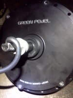
The motor arrived promptly, shipped in 4 days from Nanjing to Adelaide, South Australia, it was delivered when the tnt tracking widget said it was still in sydney. To external appearances it looks well made, now lets open it up to check inside.

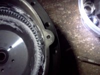
Dissassembly revealed several small defects from poor care during assembly, notable two of the casing cover screws were stripped from misalignment during insertion and the holes in the side cover were not properly countersunk and had been hand ground out larger to make the screws fit, an easy to fix defect but still a defect.

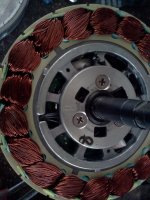
Internally everything looks good except for three small dents in the stator teeth from rough handling, probably tossed into a bin full of unwound stators after the centre is die cast in to the laminate stack, lams are 0.5mm

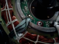
One hall wire was poorly positioned and crushed when the windings were pressed as part of the compaction process

The shaft could have been machined better as on one end the threaded section extends within the axel seal where there should be a smooth section for the seal to run on and the other end there is a smooth section but it is 0.3mm too small for the seal lips to actually touch and seal.

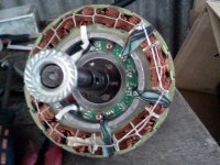
the stator is not perfectly concentric in the magnet bowl with the air gap varying around the circumference from extreemly close but not touching to about 0.6mm on the other side, the excentricity stays on one side of the stator so is not bowl wobble.

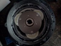
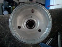
The magnet bowl looks well made but does not have the lightening slots of the bafang unit only three small 10mm holes in a solid alloy disk that holds the steel magnet backing ring.

IMHO these are all small defects and can be dealt with

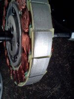
the stator has an 8 stamped on it for 8 turn and the phase bundles are substantially thick, much more so than the pissant wires that exit the axel, i took Spinningmagnets suggestion and chopped them of at the end of the axel prior to dissassembly.

On the bright side the rest of the assessment looks good andthere is nothing that would have prevented the motor from running.

It came with well positioned hall sensors and included what appears to be an integral temperature sensor glued to the stator the stator is 17mm wide and the magnets are 18mm wide there is a little flux leakage through the bowl backing but it is small holding a paper clip but not a screwdriver.

There was a small squeek from rotation the magnet bowl that turned out to be an overly long piece of winding packing paper that was scraping on the magnet bowl side plate.

Gears are the white nylon type with unsealed bearings

One side plate had an unsealed bearing and the other had a sealed one, there are standard industrial lip oil seals pressed in to both side plates but they are useless as the shaft land is too small in diameter to touch the seal lips.

The roller clutch works flawlessly and is smooth with little resistance in the freewheel direction and grips in the other like it should

The other supprise is the shaft is keyed to the clutch with 2 keys opposite each other not the 4 milled into the shaft or singly key like other models that have been examined on ES before, greenpedal says they can supply replacement clutches and gears if they are needed so this should not be a problem.

The biggest flaw IMHO is the shaft not having the right diameter polished lands for the oil seals to function as this makes using it as a hub motor with ATF difficult although they could be sleeved for a perfect seal if that was needed.

Will post testing details soon
 

Attachments

  • IMG401.jpg
    IMG401.jpg
    170.5 KB · Views: 2,703
  • IMG409.jpg
    IMG409.jpg
    121.6 KB · Views: 2,703
  • IMG416.jpg
    IMG416.jpg
    119.6 KB · Views: 2,703
  • IMG419.jpg
    IMG419.jpg
    204.3 KB · Views: 2,703
  • IMG423.jpg
    IMG423.jpg
    102.5 KB · Views: 2,703
  • IMG426.jpg
    IMG426.jpg
    241 KB · Views: 2,704
  • IMG428.jpg
    IMG428.jpg
    123.6 KB · Views: 2,263
  • IMG436.jpg
    IMG436.jpg
    154.4 KB · Views: 2,703
Sorry but I lack some of the basics to understand this conversion.

Please add a sentence or two about how the hubmotor works before conversion. Like

The magnet rotor is normally connected to the carrier by a one-way clutch? The motor stator is keyed to the axle and the wires led out the axle. The sun gear is fixed to the axle?

And then the corresponding sentences after conversion. The motor stator is unkeyed and instead bridged to the fixed hub and the wires led out of the hub. The axle is driven by the sun?

It would also help me to know the gear teeth numbers for this 4:1 & 5:1 example please. Thank you very much
 
Hi Farthingpenny your questions are all valid and all the answers and more are posted on previous pages, this is more of a quality assessment of a motor from a particular manufacturer than a general explanation of the conversion process or details. For that you should read from the beginning of the thread. At this end of the thread it is assumed that those that are particularly interested will have read the previous pages. For further details of the conversion process with this particular motor stay tuned as I will post more photos of the progress as and when I have time to complete it, these will include machining a new shaft and a new hollow magnet rotor axel through which the new shaft will pass allowing the rotor to turn on the stator and maintain ideal airgap clearance while allowing the shaft to flex minutely under load that would otherwise cause missalignment and rubbing between the stator and rotor as was found by Crossbreak and described previously on about page 23 I think. The new shaft will only have a small threaded section at the one end and have another key way machined to hold the drive sprocket and freewheel carrier that allows an either/or power by pedal motor or both to transmit force to the rear chain. There is only a need for one freewheel between the pedals and the motor shaft as the internal freewheel roller clutch allows the motor shaft to turn without the motor when un powered. The new shaft will only exit one side of the motor, the other end will be sealed, I like this particular bafang knockoff because it has a 15mm shaft inside the rollerclutch and a double keyway, this appears far stronger than the early BPMs with their four keys machined directly in to the shaft or the later ones with a thicker shaft and a single key. The reduction ratio at the end of the conversion will be 6:1 motor to shaft instead of 5:1 motor to shell.

I hope this answers your questions briefly.
 
Before conversion:

Stator is fixed to stationary shaft, motor drives planets fixed to stationary shaft with a one way roller clutch that allows free rolling without turning the motor when it is un powered and hub shell rotates in opposite direction under power,
cons poor heat shedding as the only solid conductive pathway is the axel which is steel and a poor conductor, ratio is 5:1 motor to hubshell and it has only one gear installed in the wheel centre.

Conversion:
Motor stator is unkeyed from shaft and fixed to shell, the motor drives the planet gears and they turn the shaft with the one way roller clutch at a reduction of 6:1. the shell is fixed and the new larger phase wires exit a hole in the shell not the shaft. pedals drive a freewheel on the end of the now rotation motor shaft.

Pros
Motor gets to use the gears on the rear wheel, stator can be fixed to the shell with a direct thermal pathway from the winding end turns to heatsink compound coupling to the shell allowing excellent cooling of the windings and stator.
the shaft is able to turn much faster than pedal speed through the pedal chainring to small freewheel on the shaft allowing the use of a higher rpm motor than would be suitable for in wheel use this in turn means the motor will have thicker windings of a lower resistance and the plastic gears will keep cool below the nylon glass transition temperature that kills them if the corresponding hub motor is overpowered without the extra cooling this modification affords. and as they can turn faster they can transmit much greater power levels without exceeding their torque limits .

This setup gets rid of the need for reduction ratios high enough allow the motor to drive a freewheeling crank set which is the worst weak point in many middrive setups. with the use of a 11-40 t rear cassette the ratios available compare favorably to those available from an 11-30t with a triple crank and allows the most primitive part on a bike, the front derailer to be tossed in a bin where it belongs, along with all other shitty devices that substitute precision for friction.

As Crossbreak will attest, as he is the pioneer of this conversion and the longest running user , the resultant setup is highly reliable and needs little maintenance other than new chains and sprockets and an occasional teardown clean and regrease of the motor gears.
 
Thank you for writing what I asked for. plus alot more. I had in the meantime tried to figure it myself and arrived at the following which seems to be consistent.

"In a planetary freewheeling e-bike hub motor , the outer magnet rotor is connected to the sun. The inner motor stator is keyed to the axle and the wires led out the axle. The planet carrier freewheels on the axle. The rotor drives the 16 tooth sun clockwise which drives the 64 hubring 4 times slower & anticlockwise with the carrier stopped clockwise by the freewheel to the axle. When the hub is coasting anticlockwise the sun/ rotor is not turning due to rotor cogging but the carrier follows the ring anticlockwise freewheeling.

To convert : The stator is unkeyed and instead bridged to the hub and the wires led out of the now fixed hub. The rotor again drives the 16 tooth clockwise sun to drive the carrier 5 times slower in the same clockwise direction which engages the freewheel to drive the axle clockwise. When the axle chain and sprocket is coasting clockwise axle cannot drive the carrier clockwise against the rotor drag . These directions can be reversed by turning the hubmotor unit & sprocket end for end."

I am interested in converting a small light hub motor to add electric assist to the handlebar push and pull assist I already have http://econologica.org/p2017.html. Which do you recommend for lightness, ease of conversion and price?(given that no point paying for any implied warranty as invalidated by modifying it.) (My bike to convert has an old Shimano front-freewheeling chainwheel) Thank you
 
mechhead said:
figures are for no load speed at 36v, these are the four fastest windings available they may do slower ones as well but I only have the data for the fast ones (0.5mm lams)
first number is number of strands wound second is number of turns

winding rpm speed on a 26"wheel (kmh)
9x11t 260 32
10x10t 280 35
11x9t 305 38
12x8t 336 42

Since we can pretty safely assume the same gauge wire is used for winding, then the 10x10t is the one to buy, since it has the most copper in the slot...100 strands. While the 9x11 and 11x9 have only a 1% difference at 99 strands, the 12x8 with 96 should definitely be avoided. The motors will have the same iron losses for a given rpm, so simply vary your pack voltage to get the speed you want and come out ahead using the 10x10, because it will be the most efficient motor of the bunch. Also avoid any lower speed versions with thicker lams as they will have higher iron core losses.
 
crossbreak said:
this is unloaded rpm, you should calc a factor of 0.75 for the loaded rpm. Or better find that factor using the ebikes.ca/simulator

If the best your system does is .75 of unloaded rpm, then you need a bigger motor, as you're overloading your motor. Despite wind resistance going up geometrically on my fast ebikes, I'm still able to achieve 85-90% of no-load speed with no flux weakening and speed limit set to 100%.
 
Hi John in CR,

you wrote "Since we can pretty safely assume the same gauge wire is used for winding, then the 10x10t is the one to buy, since it has the most copper in the slot...100 strands. While the 9x11 and 11x9 have only a 1% difference at 99 strands, the 12x8 with 96 should definitely be avoided. The motors will have the same iron losses for a given rpm, so simply vary your pack voltage to get the speed you want and come out ahead using the 10x10, because it will be the most efficient motor of the bunch. Also avoid any lower speed versions with thicker lams as they will have higher iron core losses."

If you read my previous posts you would note that the numbers I use from the manufacturer are (number of strands x number of turns per tooth) eg. 12x8 is 12 strands wound 8 turns per tooth not 96 strands. This means that the 12x8 has the highest kv of all and the lowest winding resistance. all versions of the BPM so far investigated on this forum have the same 0.5mm laminates and as they have a relatively low pole count, core losses are not a significant factor below about 2000rpm. this means that the higher turn counts should be used for higher voltages than 48v to keep motor rpm below 2000rpm or if the lower turn higher strand counts are used at higher voltages then the RPMs should be limited in the controller and not by the natural no load speed to below 2000 rpm .

I picked the 12x8 because it is the best match for my 80a 60v max vesc-x controller,

using the highest speed winding available allows more RPMs and so more power at the same torque as a higher turn count this is important to keep the nylon gears from being mashed although crossbreak found that the limit is shaft twisting not gears mashing if they are kept below their glass transition temperature. adequate cooling allows 2000w to be fed to this motor without problems
 
Hi Farthing Penny,

I would sugest you read this entire thread from beginning to end all 38 pages of it, for the smaller end of the spectrun i would use one of the SWX series motors like Crossbreak's original build as it seems to need the minimal amount of modification and is smaller and lighter than the ezee, mac, or bpm and also the cheapest

Further note to John in CR,
regarding noload speed vs 0.75 speed, the reason Crossbreak and others reccomend calculating drive ratios for 0.75 of noload speed is because this corresponds to the power/efficiency peak, through the use of controller based rpm limits one can set the limit to just above this point allowing application of full power all the way to the full programmed rpm with a narrower power fade ramp that that offered by the natural noload speed. If you want your comfortable maximum pedaling cadence to match the power peak of the motor this is the way to go, if you set your maximum comfortable pedaling cadence to match the noload speed you will be pedaling at only 3/4 of your maximum comfortable cadence at the point of maximum motor power availability, in the end it comes down to personal preferences about how you want the bike to feel and there is no "right" way to do it. But I like my legs maximum power to match the motor, This becomes particularly important if you use some kind of pedal assist system for motor throttle control.
 
Thanks Mechheead.

Planetary conversion is on single stage so motor still quite heavy around 4kg. Lighter (and smaller) hub motors have higher double reduction ratios as much as 17.5 on 1.4 kg YTG. The wires come out the Left side so can't they can be used as midmotors??
(Provided the mounting/adjustment slots for the axle can take the torque and the spocket is locked anti-clockwise. eg the YTG RH 35mm freewheel thread can be 3-splined with ¼” end mill and fitted with a SA 18tooth 1/8” sprocket ground down to 3/32. If the internal freewheel drag is too high, might work as keyways on a normal 16tooth freewheel mounted inside out. )

The waste heat dissipation is less than a normal motor or Crossbreak's conversion but might be ok at low power light weight end of spectrum.
 
I havn't seen a teardown of a ytg so dont know how hard it is to convert but i would think it an ideal candidate for ultra light weight.

the power level is low enough that using the hollow axel on the drive side should not be a problem and as the stator is fixed to the stationary shell after modification the cables can exit through holes in the side plate, this also allows more sensibly sized phase wires than those that have to fit through the axel, re read the thread for sprocket fixing solutions... the reason heat is not a problem on the converted hubs is that the stator is fixed to the casing via a thermal bridge that offers far better heat dissipation than the standard configuration. In the converted motor the shell is reversed and what was the left side becomes the right , where the pedal freewheel and drive sprockets have to be to see the rear sprockets. staton .com sell a large range of freewheel and sprocket shaft adapters the tricky bit is attaching something to the double flat shaft that will hold a sprocket and a freewheel. You can not fix to the freewheel thread as the shell does not turn in the modification, although there is no reason you could not use a hub as is other than the poor cooling that hubs normally offer hence the fixed shell and turning shaft mod.

running the hub as is with a SA or nexus sproket on the back of the freewheel thread along with a freewheel has its attractions namely no mods to the hub at all and you get the benefit of gears you could even seal it up properly and add atf to cool it better

I cant remember the thread name but there is someone on ES that used a small DD hub this way as a mid drive but the weight was over 4 kg

the best weight to add to an electric bike is magnets copper and iron as they do work the more the better i would not be too concerned about weight as there is power in it. I Suggested the swx series because they are lighter 3.3ish kg and can take about 1200w before the edge of saturation leads to runaway heat and increasing losses this is why crossbreak moved to the BPM
 
Thanks MechHead for underlining the heat disadvantage of just running hub motor spokeless to drive sprocket attached to hub. Thanks for filling with ATF light oil suggestion. YTG drawings were posted topic 93087 and I find it will just fit with their front axle in their rear hub between the one piece crank the shimano Front-freewheeling was sold with in North America in the 1980's.

(Silly but true reason I have to keep weight down is I have to lift the whole bike over a 3' high highway median on my normal trip.)
 
Back
Top