150A BMS "blown" at 110A during lab test. Video attached. What next?

EddySPalm

100 W
Joined
Mar 30, 2017
Messages
115
Location
Drammen, Norway
Hi,

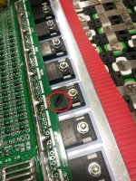
I bought the only 16s BMS I could find that was supposed to handle 150A continuous, and the other day I was testing my battery pack for temperature rise, only to find out that the batteries did fine, but the BMS did not! After roughly 1/2 minute (1 minute 25seconds into the video) at 110A we heard a "pop" from the battery, which revealed itself as being one of the transistors literally blowing up/exploding :lol:
So I am trying to get a replacement from Supower/Batterysupports, but how can I be confident that a new identical BMS will behave any differently?
Now I know I've asked this before, but can someone please recommend me a good quality 16s BMS that can handle contiuous current draw close to 150A?

Now use this golden opportunity to learn some Norwegian, and watch the ever so boring video of our battery test :D

https://www.dropbox.com/s/nd3348g3sw4wick/2018-02-23%2020.05.21.mp4?dl=0

2018-02-23 20.06.20.jpg
 
I looked up the datasheet on those FETs:

http://boorzia.com/download/HY5208W_.pdf

I don't see why that one should have blown based on the ratings. Possibly just a defective part. Most likely you can just replace (or remove) the bad one and the unit will work fine. The only other reason I could see for it blowing was if it was in the process of turning off or if the gate voltage is too low, which is easy to check.
 
EddySPalm said:
After roughly 1/2 minute (1 minute 25seconds into the video) at 110A we heard a "pop" from the battery, which revealed itself as being one of the transistors literally blowing up/exploding
A few questions -

Was this a pass transistor rather than a balance transistor? (i.e carrying the 110A)
What was the part #? It's pretty easy to look up the RdsON and current ratings and verify that they are OK. If not, perhaps replace then with better FETs.

If you can't get a FET based system to work, try a relay. There are plenty of very high current relays that should work. Arcing is an issue and will significantly reduce life, but for a BMS the relay should never open (except in a catastrophic failure, like a dead short.)
 
billvon said:
What was the part #? It's pretty easy to look up the RdsON and current ratings and verify that they are OK. If not, perhaps replace then with better FETs.

A link to the datasheet is in my post above. For sure it's the pass transistor and it should have no problems with that much current considering there are several in parallel.
 
16s 10Volt drop@110A discharge :? weak battery are poor serie connections?

The fets are more like 100A max i think?
 
fechter said:
A link to the datasheet is in my post above. For sure it's the pass transistor and it should have no problems with that much current considering there are several in parallel.
OK thanks. So the FETs are 1.7 milliohm rated to 320 amps. At 110 amps, a single transistor would see 21 watts of heat, which could cause a blowout after a while if it was the only FET carrying the load (and if it wasn't heatsunk well.) FETs should inherently current-share, but poor source or drain connections could cause one FET to carry more than its share of current.

I would look at gate drive to make sure the FETs were hard-on all the time; at those currents a marginal drive could cause a lot of heat quickly. Also at the wiring to ensure that current was really shared. And verify good heatsinking. If all look OK then I'd suspect a single bad FET.
 
Thanks for all your answers, and thank you fechter for posting the data sheet!
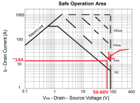
I don't understand too much of what the data sheet says, but I started studying the "safe operation area" on page 4..
At 50-60V and 110A/8 FET's = roughly 14A pr FET, is this not borderline "not safe"?? I mean, it looks to be well into the zone where you can hold the load for only milliseconds. Or am I misunderstanding something?

Safe operation FET.png
 
you are confusing the voltage across the mosfet and the battery voltage.
when the mosfet is on and conducting 14A @ 1.7m ohm x 1.5(150 ºC) voltage Vds = 35.7mV

I do not see a obvious reason for the failure

edit: what is the gate voltage?
 
EddySPalm said:
At 50-60V and 110A/8 FET's = roughly 14A pr FET, is this not borderline "not safe"?? I mean, it looks to be well into the zone where you can hold the load for only milliseconds. Or am I misunderstanding something?

Manny is correct. You only need to worry about the SOA during switching. Once it's on, it will be millivolts.

Now, if your cells sag enough under full load, one of them may have triggered an under voltage fault and made the FET turn off, at which time it could blow if the turn off is too slow.
 
Alright, so good news in the sense that I could replace the fet and possibly live happily ever after, though bad news in the sense that something might have gone wrong that I am not in control over. I can monitor the total voltage sag, like in the video, but not across every series connection. I might just have to try and see, but I don’t like the feeling of it.
I have asked Supower if they can test another BMS for me before shipping, if they are willing to replace it. If they do, then I will feel a little more safe.

What would happen if I just continued on pushing the pack after the fet broke? Because if I was out riding and this happened, I probably would never hear it.
 
Most FETs will fail shorted, so the BMS would not be able to cut off the load when it was supposed to. It could damage the pack.
If the FET failed open, then the others in parallel would take over and it might work properly.
 
First thing to check is if the nut on that FET was tight and that could be the most likely cause of it getting hot enough to pop. Second would be the thermal gasket if used or heatsink conductive paste if used (missing).
Parallel FETs usually balance the load well so that each regulate the current and heat evenly (positive temperature coefficient). A series fuse with a reverse diode if Regen is being used is another failsafe way to protect the battery pack and the controller. If that heat sink got too hot which also is likely when static testing (no movement no air flow) also something to monitor. Only other thing would be a voltage spike and an out of spec FET voltage limit on that FET.
 
https://www.energusps.com/shop/product/tiny-bms-s516-150a-750a-36

and if you really draw 100+ amps constantly you need this:

https://www.energusps.com/shop/product/lem-current-sensor-75a-750a-31

not cheap but combined with a contactor you cant blow out any mosfets as you dont use any. the contactor will act as a mosfet.

reduces your chance of the bms burning out to almost zero as the bms does not handle any current.
 
Back
Top