KT motor controllers -- Flexible OpenSource firmware for BMSBattery S/Kunteng KT motor controllers (0.25kW up to 5kW)

If I can add my 2 cents about Regen, bicycle can have their direct drive motor on front, motorcycle only on the rear, and motorcycle use Twist Throttle that you modulate perpetually. So about stability & Regen point of view, we cannot compare the two.
On top scooter or motorcycle are heavy and stable: you can lock the front brake and not fall, bicycle less likely.

This to say Regen should have variable force and be on demand, with an intuitive variable command.
This kind of command is obvious on Car and Motorcycle (where you espect anyway a natural 'slowdown' effect with their gas engine), less on Bicycle.

I sometime use the rear brake to stabilize my bicycle (going really downhill for example, or now on the ice) and would not wand an aggressive Regen, or any Regen, at that moment,
but going too fast before a stop yes please.
Last, it would be a pain if it slow you down every second you stop pedalling !

This is why pedalling backward seems so great and safe, it gives the control of when and how hard to Regen, with an intuitive command. If you have a direct drive motor, this feature is giving a very unique reason to try your Firmware ;)
 
Gaston said:
Regen, or any Regen, at that moment,
but going too fast before a stop yes please.
Last, it would be a pain if it slow you down every second you stop pedalling !

This is why pedalling backward seems so great and safe, it gives the control of when and how hard to Regen, with an intuitive command. If you have a direct drive motor, this feature is giving a very unique reason to try your Firmware ;)
My experience with ebrake by pedaling backwards is that is really useful and fun before a stop.

Current code has a small delay, like a buffer (on the PI controller I term, that slows down a bit the response of throttle. Also the regen current is configured to be 0 while running and is set to max while braking and will have a specific value by pedaling backwards. So, even with throttle 0, should not slow down -- at least I didn't feel slow downs yesterday.

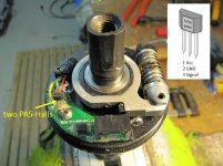
Are you aware that you will have to use torque sensor and modding it with a PAS to get that feature you like?? https://opensourceebikefirmware.bitbucket.io/development/Various--2017.12.01_-_Regen_ebrake_like_coast_brakes.html
 
casainho said:
Are you aware that you will have to use torque sensor and modding it with a PAS to get that feature you like??

You don't have to add an additional PAS, you just have to solder the yellow wire of the torque-sensor to one of the PAS-Halls directly...

Torque Sensor Hall mod.jpg


Why do you have to use the torque sensor? A "normal" PAS should work also?!

regards
stancecoke
 
Gaston said:
This to say Regen should have variable force and be on demand, with an intuitive variable command.
This kind of command is obvious on Car and Motorcycle (where you espect anyway a natural 'slowdown' effect with their gas engine), less on Bicycle.

Backwards pedaling is not the only way of variable regen, you can mod the brake lever as Stancecoke posted few months back or use another throttle (thumb or half twist) on left side. But its working only with Stancecoke's fw now.

Anyway, I have to say that backwars padaling regen is easiest (no modifications) if it will work with PAS only. Also maybe a good idea to make it activated only by brake lever sensor+backwards pedal

Thumb or lever variable regen can be as responsive as clasic brakes.

Most users have motor on rear wheel
 
casainho said:
A friend that repairs electric bicycles and motor cycles, told me what Stancecoke also told recently - some motor cycle controllers, do regen a bit when user apply throttle and the motorcycle is moving, and I think we can do that with our hardware.
The thing is, if we release the motor phases then we don't have regen. Would you prefer to have no regen while riding an ebike?? Well, for motorcycles, my friend told me it can be like when user releases the throttle, it open motor phases and when user then apply regen, it starts regen -- maybe you are riding more like a motorcycle.
I have that "bit" of regen while aplying throttle with stock fw and really dont like that, so if we are able to set the zero current that well so we will not feel resistance, then I would prefer this.

But I think its possible to release phases and when you add throttle or regen - it reactivates them with the zero current (it knows rpm from halls so it should be able to guess?) And as fast as posible when it gest enough feedback from phases it reacts to throttle/regen

All above as fast so you cant see a delay compared to as it is now.

I ride more like a motorcycle, thats true. It may not be that important for you guys.

But the controller/fw has a potencial to be used on road legal small motorcycles :)
 
ALERT!!

ADC_MOTOR_REGEN_CURRENT_MAX and ADC_BATTERY_REGEN_CURRENT_MAX, any of the them CAN'T be more than 66 units!! Other way motor will start and go to max speed!!!

This a limitation of the hardware. I was using like 120 units and that did overflow to about 200, because there is a subtraction:
Code:
ui8_adc_target_motor_regen_current_max = ui8_adc_motor_current_offset - ui8_value;

ui8_adc_motor_current_offset is about 75 on my S12S. So 66 seems to be a safe value.
 
After the last changes the switch from 60 to 360° interpolation works, so I cant even tell when it switches. Works really good.

I tested a lot on table and all the limitings are doing their job with both 6fet and 18fet

Interesting find - I tried setting rotor angle to where it shows lowest noload battery amp draw. (With interpolation switch at 200 so it never switches) and I found that for the test motor 218-219 shows almost the same current, 217 takes more, but 220+ seems like hiting some limit at high rpm, starts cutting like 2 times a second. It can't be max erps!

Is this the right way to set it or I will find lower value better at real ride?
 
stancecoke said:
You don't have to add an additional PAS, you just have to solder the yellow wire of the torque-sensor to one of the PAS-Halls directly...
Thanks for the info.
But, you mean adding an extra cable to carry the PAS-Halls signal directly?

stancecoke said:
Why do you have to use the torque sensor? A "normal" PAS should work also?!
Because I implemented for torque sensor. To be clear, I am implementing for my needs and I hope you guys don't expect that I will implement all ideas/features. And that is because I don't have much free time nor resources.
 
honya96 said:
After the last changes the switch from 60 to 360° interpolation works, so I cant even tell when it switches. Works really good.

I tested a lot on table and all the limitings are doing their job with both 6fet and 18fet

Interesting find - I tried setting rotor angle to where it shows lowest noload battery amp draw. (With interpolation switch at 200 so it never switches) and I found that for the test motor 218-219 shows almost the same current, 217 takes more, but 220+ seems like hiting some limit at high rpm, starts cutting like 2 times a second. It can't be max erps!

Is this the right way to set it or I will find lower value better at real ride?
I just know that this ways:
- https://opensourceebikefirmware.bitbucket.io/development/heets_and_application_notes--Endless-sphere.com_forum_messages--2018.02.20_-_Reading_motor_phase_current_from_the_DC_link_current_(shunt).html
- // This value can be tested with motor running at medium speed, where it is already running with sinewave interpolation (not at startup)
// A way to test: put the motor with the same mechanical load (like on a bike training roller) and with a constant speed
// changing this value will make the motor to need more or less current to mantain the same speed -- adjust to use the least current possible
 
Got the ebrake working by pedaling backards, using the torque sensor I modded as shown here: https://opensourceebikefirmware.bitbucket.io/development/Various--2017.12.01_-_Regen_ebrake_like_coast_brakes.html

It is disabled by default on the code but instructions to enable are on config-example.h. The code is on master branch.

So, while riding again, I found that the vibrations happens only at startup or at hills, so, when current is being limited.
I think the firmware on direct drive motors must be better tested and developed -- I hope to do it with time, as my main bicycle has that type of motor.
 
casainho said:
But, you mean adding an extra cable to carry the PAS-Halls signal directly?
No, just using the existing yellow wire for the unprocessed PAS signal. I guess, the raw signal is not exactly symmetrical, so the direction detection should work with just one PAS hall.

index.php


regards
stancecoke
 
Guys, I really tried to solve this without bothering you, but I cant get my bike to "soft start"

the smallest amount of power I can get with just slightly added throttle is about 500w. I tried setting like everything in reasonable range at config.h and main.h

I think it may be the problem with jump at interpolation switch point (its back with direct motor) it increases rpm when switching to 360° and also when getting back to 60°without throttle.

But I am not sure, because the start power is same with 60° only.

direct pwm duty cycle starts with extremly low power but then at some point (throttle position/rpm) it adds way too much (my throttle HW is ok)

Can it be still wrong rotor angle?

At main.h
PWM CYCLE MAX 254
PWM CYCLE MIN 20
why is min. 20 and not 1?
 
Please don't enable DO_SINEWAVE_INTERPOLATION_360_DEGREES. I don't use it, only 60 degrees interpolation - I don't know if any motor works well with 360 degrees interpolation... That is experimental.

If you find that thing happens on transition from no interpolation to interpolation 60 degrees, happens that FOC also starts at
// minimum speed to do FOC
if (ui16_motor_speed_erps > MOTOR_ROTOR_ERPS_START_INTERPOLATION_60_DEGREES)

Maybe the angle before FOC and after FOC are very diffetent... Maybe you van also adjust the ERPS at FOC starting....
 
Ok I mean from no interpolatiom to 60.. I tried values from 5 to 300 (300-never switch)

So "FOC" starting and 60° interpolation are 2 different things?
 
When I receive the controller, what I have to do to remove the read-only protection using Windows as OS? Also, how can I make a dump of the original firmware written in the ST chip?
 
honya96 said:
Ok I mean from no interpolatiom to 60.. I tried values from 5 to 300 (300-never switch)

So "FOC" starting and 60° interpolation are 2 different things?
I am almost sure your issue happens because FOC starts and not the interpolation. So, start by disable FOC:
Origonal code:
Code:
// minimum speed to do FOC
    if (ui16_motor_speed_erps > MOTOR_ROTOR_ERPS_START_INTERPOLATION_60_DEGREES)
Change to:
Code:
// minimum speed to do FOC
    if (ui16_motor_speed_erps > 1000)
    {
So, let's see if that issue happens without FOC running.

If so, probably you have a very different start angle from the one FOC setup, hence that big change in speed and current.
 
racingame said:
When I receive the controller, what I have to do to remove the read-only protection using Windows as OS? Also, how can I make a dump of the original firmware written in the ST chip?

You can't make a dump, as there is the read/write protection. That's usual to protect the intellectual property of the developer.
You can disable the protection with a click on the button "Write Option Byte" in the java tool. See here.
But with this click, the original firmware is erased and there's no way back to stock firmware.

regards
stancecoke
 
honya96 said:
Guys, I really tried to solve this without bothering you, but I cant get my bike to "soft start"

the smallest amount of power I can get with just slightly added throttle is about 500w. I tried setting like everything in reasonable range at config.h and main.h

I think it may be the problem with jump at interpolation switch point (its back with direct motor) it increases rpm when switching to 360° and also when getting back to 60°without throttle.

But I am not sure, because the start power is same with 60° only.

direct pwm duty cycle starts with extremly low power but then at some point (throttle position/rpm) it adds way too much (my throttle HW is ok)

Can it be still wrong rotor angle?

At main.h
PWM CYCLE MAX 254
PWM CYCLE MIN 20
why is min. 20 and not 1?
I'm not certain if it will work with larger direct drive motors,to do FOC you have to be able to work out where the stator flux is in relation to the d and q axis of the rotor. To do this you either have an encoder or sensorless observer to determine the rotor angle and an electrical model of the motor to estimate where the stator flux is in comparison to the rotor.

The way this firmware works is closer to an open loop sinewave controller but has a small degree of feedback via hall sensors but only enough resolution on the rotor position to determine that it hasn't totally desynced but not enough to detect minor deviations from the q axis. If you feed a BLDC motor 3 current sinewaves spaced 120 electrical degrees apart it will naturally align itself provided there is enough current and the speed isn't too high, if the motor never experiences a load that is significant enough to overcome it's torque it will remain in sync with the stator.

On a low inductance geared motor this probably isn't much of an issue, gearing means it doesn't deal with large torque loads and low inductance means there's not much delay between the hall sensor and where the controller assumes the stator flux is. On a larger direct drive motor it's very different, it's expected to produce much more torque and will desync if it drifts from the rotor q axis. Secondly the larger direct drive hub motors have significant inductance, this means they resist changes in current and magnetization is delayed. If the delay causes the stator flux to align with the rotor d axis then it's possible the controller tries to keep the rotor aligned with the hall sensor output but is wasting most of the current generating flux far from the q axis.

The original firmware must have some work around for this situation without having to use cpu intensive FOC calculations, possibly they use the current sensor to measure how long it takes for the current to rise and they have a look up table of expected results based on the inductance range most ebike motor come in. One way it might be possible to test it would be to see if the original firmware can run motors with inductance values that are very different to common ebike motors.
 
Hello, can I ask you how can I learn how to write a firmware for a brushless motor from scratch, how did you figure it out how to do it? I've always written software, but when it comes to write a firmware I have no clue where to start from or where to look for getting some information. Also, looking at your code, I can't really figure out all the physics/mathematical formulas parts. I have so many ideas, so many things I'd like to include in my firmware and would really like to learn how to implement all of them.

For example, I'd like to customise your firmware to add support for gearsensor , but how to do it? It has a HIGO connector, so first of all I have no clue where I should plug it to my S12S controller in order for it to work, also I have no clue what kind of data it sends to the controller, how do I sniff/debug those packets sent from the gearsensor (or any other device like brakes, PAS, etc.) to the controller when I change gear, and how do I create a event handle that gets triggered when getting that precise input.

Sorry for the long message, I'd like to get some help where I can start from to learn something by myself. :p
 
I've used the fine weather today to do a testride with the linear regen function :)
I found that we have to disable FOC while regen, as the advance angle runs to nirvana otherwise.
With this small change in the code, it works well now. I use a thumb throttle (thumb brake :wink: ) for controlling the regen. I used the torque sensor and rode in torquesensor-mode. Now I can confirm, that the modding of the torquesensor with the raw signal of one PAS-Hall works well, the direction detection is OK.

regards
stancecoke
 
racingame said:
Hello, can I ask you how can I learn how to write a firmware for a brushless motor from scratch, how did you figure it out how to do it?
As you are familiar with developing software, just try to understand the code in the ebike-app.c of the master branch, or the update_setpoint.c of the HighSpeedMotor fork on github.
That's the part you will need if you want to implement the gearsensor.
If you want to understand how to do the commutation of the BLDC you can find detailed information in the internet, but this is a real deep dive and not necessary for implenting the gearsensor.


racingame said:
For example, I'd like to customise your firmware to add support for gearsensor , but how to do it? It has a HIGO connector, so first of all I have no clue where I should plug it to my S12S controller in order for it to work, also I have no clue what kind of data it sends to the controller

Do you have a link to the gearsensor? I guess it just pulls the signal pin to gnd, when a gear shift is detected. So you can use the brake input of the controller to make the middrive motor stop to avoid shifting under full load.

regards
stancecoke
 
racingame said:
Hello, can I ask you how can I learn how to write a firmware for a brushless motor from scratch, how did you figure it out how to do it? I've always written software, but when it comes to write a firmware I have no clue where to start from or where to look for getting some information. Also, looking at your code, I can't really figure out all the physics/mathematical formulas parts. I have so many ideas, so many things I'd like to include in my firmware and would really like to learn how to implement all of them.

For example, I'd like to customise your firmware to add support for gearsensor , but how to do it? It has a HIGO connector, so first of all I have no clue where I should plug it to my S12S controller in order for it to work, also I have no clue what kind of data it sends to the controller, how do I sniff/debug those packets sent from the gearsensor (or any other device like brakes, PAS, etc.) to the controller when I change gear, and how do I create a event handle that gets triggered when getting that precise input.

Sorry for the long message, I'd like to get some help where I can start from to learn something by myself. :p
As I got originally this message as private, I will answer also.

First: I am really happy to see another user/developer that likes ebikes :)

I started some years learning and playing with ebikes motor controllers. I am being learning by reading application notes for how to control brushless motors, that semiconductors write and share in the hope that developers will develop motor controllers using their microcontrollers. I also learn a lot from OpenSource projects and there are some for firmware motor controllers. I am sharing my notes for the others here, including that application notes, links to projects, forum messages, etc:
- https://opensourceebikefirmware.bitbucket.io/development
- https://eggelectricunicycle.bitbucket.io/

As Stancecoke already told, motor.c is the file for controlling the motor and ebike_app.c the place were I put the things for ebike applications, however sometimes I need to put bits on motor.c that will be used on ebike_app.c.

There aren't much "physics/mathematical formulas", sometimes is more quick and dirty algorithms.

I don't know nothing about that sensor, what it should do, etc. But always start looking on forums to see if anyone already disassembled it and shared how it works, etc. Can you please share with us links, etc?? and do you know what it should do when we shift gears, what it should to to the motor, etc??
 
stancecoke said:
I found that we have to disable FOC while regen, as the advance angle runs to nirvana otherwise.
Hmmm... how did you observe that??

I remember to see on oscilloscope that the phase B current signal inverts / shifts 180º when doing regen... so maybe we need also to invert the FOC algorithm when motor current is negative!!

stancecoke said:
I use a thumb throttle (thumb brake :wink: ) for controlling the regen. I used the torque sensor and rode in torquesensor-mode. Now I can confirm, that the modding of the torquesensor with the raw signal of one PAS-Hall works well, the direction detection is OK.
Did you used "my" branch?

About that mod to torque sensor, so in the end we have an usual PAS signal and not the original torque sensor PAS signal that when we pedal backwards it keeps at high level signal?
 
stancecoke said:
If you want to understand how to do the commutation of the BLDC you can find detailed information in the internet, but this is a real deep dive and not necessary for implenting the gearsensor.
I thought this firmware uses FOC sinusoidal commutation, not BLDC?
Anyway, besides implementing extra functions on your already working firmware, I'd like to better understand how to write a firmware from scratch, I think easiest is PID controller so I'm looking into that. Do you have any EVB brushless to advise, a developer board for brushless motors with a demo firmware already written and working?

stancecoke said:
Do you have a link to the gearsensor? I guess it just pulls the signal pin to gnd, when a gear shift is detected. So you can use the brake input of the controller to make the middrive motor stop to avoid shifting under full load.

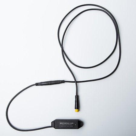
Official site: http://gearsensor.com/
1461916218_449536-original.jpg

Originally, it was connected in series to a brake, on newer motors they started making a dedicated cable for it. The problem of having the gearsensor in series to the brake was that it had a higher activation time/latency for the cutoff.

Basically, what I'd like to do is implement 10 profiles for current and speed (https://i.imgur.com/1BY5MzA.jpg) + add an extra cutoff column and change the cutoff timing for each assist level. In addition, I'd like to link this cutoff timing also to my current speed and current gear.

The reason for this is, the gearsensor is amazing, but it has a bid problem. If you go buy any motor that implements it (bafang, brose, etc.), you notice they use the same exact cutoff timing for all assist levels and gears, and what happens is that at higher gears you can feel the motor tear off. Thus I'd like to take this great tool, intercept the signal sent by it every time you change shift, but customise the cutoff time for every single assist level, for every single gear, and also based on what's my current speed

I'd be just happy to have 10 profiles with 10 different cutoff times as a starting point tbh (something like this: https://i.imgur.com/Y0CVPYA.jpg). :mrgreen:
 
Back
Top