End turns bad?

Buk___ said:
Apart from siding with/showing support for major, you don't add anything.

1) I've researched this subject before because I found myself wondering why end turns don't contribute to torque. I found a lot of credible references confirming they don't, but I couldn't much in the way of explicit explanations and those I did, I didn't fully grasp. That is a failing in my research effort and my knowledge and understanding. You are in the same boat.

2) I know from prior reading that Major is something of an expert on the subject of motor design. It is an expedient skill to utilise the knowledge of others where your own is lacking - you don't have to be right all the time.

3) Your attitude has been somewhat aggressive and condescending at times. You've flat out told people they are wrong while claiming to be simply asking for an explanation. You seem to be doing a lot more talking that listening.


FWIW, that only windings that are at right angles to the magnets generate force now makes sense and I have a few ideas as to why whereby I'm satisfied that one of them is likely correct. But I would not be confidence explaining why to someone else and answering any questions they might have. This is sufficient for me for a casual understanding - I'm only satisfying my idle curiosity. The explanations in this thread have help and I've read them with interest.
 
Buk___ said:
It ain't guesswork, assumption or speculation. It's simply fact.

Perhaps you'd like to consider a theoretical motor with the winding eliminated from the slots and conductor only passing along the side of the teeth? I'm not sure if this could actually be made (it'd maybe be like an radial flux motor winding arrangement stuck to the sides of a radial flux stator with radial magnet ring. You seem to be suggesting this kind of motor ought to work pretty well?
 
Buk___ said:
kiwifiat said:
end turns do not produce stator flux that is orthogonal to the rotor flux and therefore do not contribute anything towards torque production.

The coils do not interact with the magnets to produce torque. They are too far away.

The end turns -- as with the through-slot runs -- induce flux into the tooth core, and it is that flux emanating from the face of the tooth that interacts with the magnets to produce torque.

If BLDCs relied upon Lorentz force for torque, they would produce very little, because the closest turns only receive <10% of the magnets field strength; and those at the bottom of the tooth <0.0001%. (Check the math above or do your own!)

Beside which, the current in the half of a turn on one side of a tooth runs in the opposite direction to that flowing in the other half of that same turn. Same current but 180° opposite direction, same field strength (more or less) same direction; the Lorentz forces produced by the two sides of each and every turn cancel each other out!

It ain't guesswork, assumption or speculation. It's simply fact.

A logical extension of your argument is that a coreless motor could not possibly run since the Lorentz forces cancel. You might want to have another think about your facts and how exactly you understand an electric motor operates. In particular ask yourself over what electrical angle is force generated? And yes when a stator tooth is directly over a rotor pole there is no force generated, a fact for sure but one that adds nothing to the discussion about the usefulness of end turns. The Lorentz force equation is all about the cross product of stator flux produced by current flowing through active turns and rotor flux. In a coreless motor the force is generated directly on the copper windings and the structure that holds them. Yes in a cored motor it occurs at the air gap interface at the tooth tip. Regardless it is still a Lorentz force.

Regarding your assertion that rotor flux has no influence on stator windings, as Major proposed, how do you imagine BEMF is generated? Are you aware that using SI units Kt in Nm/A = Ke in Vs/rad. What this unequivical fact tells us is that if there is no BEMF there can be no torque.
 
kiwifiat said:
Yes in a cored motor it occurs at the air gap interface at the tooth tip. Regardless it is still a Lorentz force.

Okay. Lorentz force is a magnetic field, interacting with current in a conductor to produce a force.

If "it occurs" -- a force is produced -- "in the air gap"; it can not be a Lorentz force, because there is no conductor or current in the air gap.

When two magnets attract each other, there is also no current and no conductor; and no Lorentz force.

At the air gap interface, the flux produced within the tooth, interacts with the flux from the magnets. Simple magnetic attraction/repulsion.


kiwifiat said:
Are you aware that using SI units Kt in Nm/A = Ke in Vs/rad. What this unequivical fact tells us is that if there is no BEMF there can be no torque.

Of course there is BEMF.

If the field in the coils combine to produce a field in the tooth which completes its magnetic circuit via the magnet, the back-iron, the adjacent magnet(s) and the common core ; why wouldn't the flux flowing around that same circuit, driven by the magnet, act back on the coils?

It does, hence BEMF.
 
Buk___ said:
kiwifiat said:
Are you aware that using SI units Kt in Nm/A = Ke in Vs/rad. What this unequivical fact tells us is that if there is no BEMF there can be no torque.

Of course there is BEMF.

If the field in the coils combine to produce a field in the tooth which completes its magnetic circuit via the magnet, the back-iron, the adjacent magnet(s) and the common core ; why wouldn't the flux flowing around that same circuit, driven by the magnet, act back on the coils?

It does, hence BEMF.

So the rotor flux does interact with the windings then?

My BEMF statement needs to be qualified to if Ke = 0 there can be no torque, a motor with Ke ≠ 0 will generate stall torque at zero rpm. If as you state there is no interaction between rotor flux and the stator windings in a cored motor there can be no BEMF.

What is your explanation for a coreless motor operation if it doesn't rely on Lorentz forces?
 
Buk___ said:
Have you ever seen the classic demonstration of oscillating a bar magnet in and out of an air coil to generate electricity? Essentially, one of these:

I think it depends on the field lines. In the case of the air coil with the magnet oscillating in and out, the fields are shorting out like the magnetic field of the earth (in all directions everywhere around).
But on a BLDC motor most of the field lines are oriented radially. Or with other words: the magnet circle is different.

If voltage would be induced in the endturns, it would be also induced in the core which would mean huge eddy losses as the core is not laminated in this direction.
Thats my understanding, but i am not a motor engineer or have studied this subject.
 
honda-smc-fig-2-1.gif


Honda found a clever bus bar winding path for this SR motor topology that eliminates half the end turn resistance losses.

The current path should be as wide and short as you can achieve while still achieving the BEMF/Kt needed to work with the controller.

In some large motors the end turns are large bolted plates made as thick as they can package on the sides. Thus reduces R and improves cooling of the copper in the slot. For pancake motor geometries this potentially enables adding another turn while maintaining the R of a lower turn count motor, but requires a tremendous amount of effort to build one, and it would have a weight penalty with the added copper that likely would make a better motor by adding the same mass to increasing motor radius by whatever amount the same mass offers.
 
Buk___ said:
If "it occurs" -- a force is produced -- "in the air gap"; it can not be a Lorentz force, because there is no conductor or current in the air gap.

Just like your solenoid there is a magnetic core at the air gap... Does a solenoid stop working if the iron core protrudes a significant distance from the end of the coil?
 
Punx0r said:
consider a theoretical motor with the winding eliminated from the slots and conductor only passing along the side of the teeth? I'm not sure if this could actually be made (it'd maybe be like an radial flux motor winding arrangement stuck to the sides of a radial flux stator with radial magnet ring.

Yes. I believe that could be made. I'll look into modifying a fan motor.

Punx0r said:
You seem to be suggesting this kind of motor ought to work pretty well?

Work, yes. How well, we'll see.
 
kiwifiat said:
Buk___ said:
Of course there is BEMF.

If the field in the coils combine to produce a field in the tooth which completes its magnetic circuit via the magnet, the back-iron, the adjacent magnet(s) and the common core ; why wouldn't the flux flowing around that same circuit, driven by the magnet, act back on the coils?

It does, hence BEMF.

So the rotor flux does interact with the windings then?

The "rotor flux" -- the flux from the magnets -- interacts -- links through -- the tooth core, as a part of the magnetic circuit.

The flux in that magnetic circuit -- when passing through the tooth core in close proximity to the windings -- interacts with them. As the magnets pass by the end of the tooth, the flux in the magnetic circuit varies; waxing and waning in strength as the face of each magnet presents more or less of itself to the face of the tooth; and inverting as the different polarity magnets pass by.

It is this changing flux passing through the tooth, close to the windings, that induces the BEMF in the windings.

kiwifiat said:
My BEMF statement needs to be qualified to if Ke = 0 there can be no torque, a motor with Ke ≠ 0 will generate stall torque at zero rpm.

If you lock the rotor so that it cannot move and then power the windings, then the attraction & repulsion between the fields induced in the teeth, and the (locked) rotor magnets exists, and produces a torque that would be detected pressing against whatever is locking the rotor. No motion needed.


kiwifiat said:
If as you state there is no interaction between rotor flux and the stator windings in a cored motor there can be no BEMF.

I said direct interaction between the magnets and the windings. The rest is refuted (again) above.

kiwifiat said:
What is your explanation for a coreless motor operation if it doesn't rely on Lorentz forces?

Proximity and imbalance.

Proximity: the windings are in the airgap. As close to the magnet faces as manufacturing tolerances will allow. The coils are very narrow -- just one or a few turn wide axially -- so they are all within a few mm or less of the face of the magnets. Lorentz force is maximised by close proximity.

(In a toothed BLDC, the first (nearest) turns are often (for the Axial flux; always for the ThinGap) further from the magnets than the entire width of coil in the airgap coiled motors; and those furthest away can be 30, 40, 50 mm. )

Unaided, the field strength from the magnets falls of 1/R^3 of the distance. That means that if the field strength of the magnet is down to 50% (and it is much lower) 5mm away, then it will be 50/8 = 6.25% after 10 and 50/27 = 1.85% after 15mm. Its both more complicated and much worse than that, but it serves to illustrate the exponential falloff.

Imbalance: Two cases:

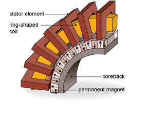
Axial flux: Firstly, air cores/solenoids act like bar magnets, just as wound teeth do, just shorter and fatter. Which is to say, the attraction and repulsion between the individual cores an the adjacent magnets as they align then switch, is just as real and powerful as the tooth/magnet interactions in a toothed BLDC.

There is also, due to proximity, Lorentz force at work. But even this is not so much as you might hope. At the single position documented in the following picture

6 of the 8 sides in one of the powered phases are producing anticlockwise torque and 2 clockwise.
5 of the 8 sides of the second power phase are produce anticlockwise torque and 3 clockwise.

Net state: Of the 16 powered sides, 10 are counterbalancing each other, leaving just 6 to produce useful torque. But rotate it a little, and the balance changes to the exact same 6 of 16 creating torque, but in the opposite direction.

:AxialFluxImbalance.jpg

And if you want to step through putting the rotor in (say) 360, 1 degree rotations and adjusting the phases and directions to suit the commutation, the end result is that over a single cycle, the net Lorentz force is going the right way half the time and the wrong way the other half.

You (nor most others) won't believe me, but please try it for yourselves. You don't need to do all 360 1deg positions; stats says that if you do say 40 or 50 at randomly chosen positions, your result will be a very strong indicator of the full result.

Thin gap: If you've ever look closely at the ironless composite stator of a ThinGap motor, you'll see that the copper angles (or chevrons) across the width of the stator. You can just make it out here and here if you blow them up and look closely. (It's clearer in the second, chevroned example image.)

In part that is done to reduce cogging, like slanting the slots in a normal bldc; but it also distributes the copper of each individual turn over a much wider area. If you could see through the chevroned stator, and picked out an individual turn, it would look diamond shaped; with one half of the diamong on the outside, and the other on the inside.And the width of that diamond spreads further around the stator than the a single magnet,

The upshot in both angled and chevroned case is, the flux strength affecting one half of each turn on the outside, is markedly different to the flux strength affecting the other side -- say, the edge of the magnet vs. the middle, or the opposing poles of two adjacent magnets. And the bottom line is that there is never a situation where the fields affecting the two halves of any given turn are in balance.

I have (or had) a copy of the ThinGap patent document that describes it in some detail; I'll try to find it.

(The same is true to an extent for normal BLDCs & axial flux motors, but it a quirk (and factor of) the mismatch of poles to teeth; not a fundamental and critical design criteria as with the ThinGap.)
 
liveforphysics said:
honda-smc-fig-2-1.gif


Honda found a clever bus bar winding path for this SR motor topology that eliminates half the end turn resistance losses.

The current path should be as wide and short as you can achieve while still achieving the BEMF/Kt needed to work with the controller.

In some large motors the end turns are large bolted plates made as thick as they can package on the sides. Thus reduces R and improves cooling of the copper in the slot. For pancake motor geometries this potentially enables adding another turn while maintaining the R of a lower turn count motor, but requires a tremendous amount of effort to build one, and it would have a weight penalty with the added copper that likely would make a better motor by adding the same mass to increasing motor radius by whatever amount the same mass offers.

It's a transverse flux machine; quite different to other topologies and far from unique.
 
Punx0r said:
Buk___ said:
If "it occurs" -- a force is produced -- "in the air gap"; it can not be a Lorentz force, because there is no conductor or current in the air gap.

Just like your solenoid there is a magnetic core at the air gap... Does a solenoid stop working if the iron core protrudes a significant distance from the end of the coil?

No. But a solenoid doesn't use Lorentz forces or create torque!

Though if you lay it loose on a table and hold the pole of a magnet near the end, it will twist when attracted to, or repulsed from that magnet depending on orientation. A torque created, but no Lorentz force in sight.
 
Alan B said:
https://www.physicsforums.com/threads/influence-of-motor-winding-end-turns-on-torque.819001/

I see we're not the only ones who can debate the topic.

I'm sticking to my theory that the end turns do contribute to the flux (and therefore the torque) as long as they are in close proximity to the stator iron. In the case of a coil with no iron, then things are quite different.

Imagine a motor where the iron pole are cylindrical and the windings are circular. The flux generated will be a function of the amps x number of turns x area. In a circular pole, the windings contribute equally from all directions and rotating the windings with respect to the core would make no difference in the flux.

Imagine a motor where the stator poles are bent at 90 degrees and the copper is wound beyond the bend. The iron will carry the flux to the pole face regardless of the bend. All the copper could be like an end turn.
 
It's PMSR (like a model 3 rear drive motor) radial inrunner not transverse flux (not that it would matter).

The end turns do obviously make magnetic fields proportional to current, but the axis they produce the field makes thrust axis direction forces on the rotor vs torque forces, and when it's symmetrical end turns on both sides of the tooth the thrust axis forces balance out.

You can do an easy experiment to find out by wrapping say 5turns around a given motor tooth as tightly as possible, applying say 10amps through that winding and measuring the torque needed to cog the motor over.

Next, wind a tooth with the same 5 turns, but have the end turns hanging way out of the slot however far you want, so the end turns are feet away from the motor if you want.

It will make the exact same cog-over torque at the same 10amps, it just means that to drive the same 10amps it requires higher voltage due to higher winding resistance from being a longer path.


Buk___ said:
liveforphysics said:
honda-smc-fig-2-1.gif


Honda found a clever bus bar winding path for this SR motor topology that eliminates half the end turn resistance losses.

The current path should be as wide and short as you can achieve while still achieving the BEMF/Kt needed to work with the controller.

In some large motors the end turns are large bolted plates made as thick as they can package on the sides. Thus reduces R and improves cooling of the copper in the slot. For pancake motor geometries this potentially enables adding another turn while maintaining the R of a lower turn count motor, but requires a tremendous amount of effort to build one, and it would have a weight penalty with the added copper that likely would make a better motor by adding the same mass to increasing motor radius by whatever amount the same mass offers.

It's a transverse flux machine; quite different to other topologies and far from unique.
 
Alan B said:
https://www.physicsforums.com/threads/influence-of-motor-winding-end-turns-on-torque.819001/

Interesting, thanks.

The last line of the last post by the OP, and the second last line of the thread:

The bottom line is that I still don't have an explanation of the effects of the end turns on these small motors that I am comfortable with.

I understand his frustration. People are so wedded to the idea that end turns have no contribution to the function and power of the motor, but it does not stand up to analysis. As I hope to demonstrate more convincingly, but damn FEA is slow.
 
liveforphysics said:
It's PMSR (like a model 3 rear drive motor) radial inrunner not transverse flux (not that it would matter).

Sorry, but this article contains the exact same picture you posted, and it is headlined:

SMC cores in Honda’s prototype Transverse Flux Motor for hybrid powertrains

And this paper by the guys at Honda that developed it:
Development of Transverse Flux Motor with Improved Material and Manufacturing Method
both call it a 'Transverse Flux motor'.

Both also contain this image which clearly show it to be a TF motor not a PMSR.

http://www.pm-review.com/wp-content/uploads/2013/07/honda-smc-fig-1-1.gif
 
They can call it whatever they like, I still see that as a radial SRPM inrunner.

This diagram is transverse flux to me, but I'm fine if due to nomenclature preferences the Honda motor is labeled transverse flux due to it using most/all of the available winding at a given moment.

RTEmagicC_ctl1102f1-Motors-fig_3-final.jpg.jpg
 
Run the above proposed test for yourself winding a tooth with massive size/length end turns and shortest possible to wind end turn lengths and see the torque required to cog it over with the same winding current.
 
fechter said:
Imagine a motor where the iron pole are cylindrical and the windings are circular. The flux generated will be a function of the amps x number of turns x area. In a circular pole, the windings contribute equally from all directions and rotating the windings with respect to the core would make no difference in the flux.

Imagine a motor where the stator poles are bent at 90 degrees and the copper is wound beyond the bend. The iron will carry the flux to the pole face regardless of the bend. All the copper could be like an end turn.

Exactly. Nice thought exp :)
 
Alan B said:
Is part of the problem here the definition of the "end turns"?

The coil around the tooth makes flux in the tooth. Flux in the tooth is good.

The lead from that coil to the next tooth is the "end turn" and, the wire, once it leaves the tooth, makes wasted, non-focused "bad" flux.

I agree, the stretches of conductor between teeth are non-contributory.

But I do not think that definition of "end turn" is what most people think when the read it or use it. Including most if not all of those contributing to this thread.
 
Current flow on opposite sides is in opposite directions and the opposite sides of the wire's magnetic field on those turns are in the core and end up being THE SAME DIRECTION so they add ... Again wrong assumption! (Your fingers are the turns and they travel in a circle, index finger is current flow and thumb is magnetic field direction.)

Sorry this reply ended up way down from the intended post...
 
Back
Top