kWeld - "Next level" DIY battery spot welder

I have done some progress in the setup of my Kweld and as predicted by tatus1969 my 3S5P LiPo is too big and I exceed the 2kA limit. I had error during calibration so following his advice I reduced the voltage.
With 2S5P I calibrated the welder and obtained a R=1.24 mR then I tested Kweld with pure nickel strips 0.2mm and 0.3mm with suggested energy level in the operation manual and the results are very good.
This is what works for me:
20180224_171502_1.jpg


With my 3mm copper electrodes I can make very close spot welds, this is what I obtained:
20180224_171019_1.jpg

20180224_171114_1.jpg


20180224_172356_1.jpg

20180224_172552_1.jpg


I also would like to spot weld copper strips 0.1mm ans 0.2mm and I read that tungsten electrodes are needed so I tried to make these copper tungsten electrodes with some tungsten wire I had that is the same used as oven resistances.
20180304_191813_1.jpg


The mechanical contact is the best I can make but I can not calibrate the welder and I have the error Timeout; R=17.11m; STD=532

Is there anybody here that succeeded to use tungsten electrodes with Kweld?
 
@bigbore, thanks for posting. That really looks impressive!
 
Today I have received EC8 connectors with housings, rated for 180A continuous it looks like great candidate to upgrade XT-90. It also accepts thick cables up to 7mm diameter.
 
Big bore, At high energy levels, the sharp tips of copper or brass electrodes can melt slightly, and stick to the nickel strip (or copper/brass strip). Tungsten is one of the options due to its extremely high melting temperature, so they shouldn't stick.

I have also read about carbon-arc gouging rods used for electrodes for the same reason when using high-amp resistance soldering for copper plumbing joints. I have no idea if these will work for spot-welding electrodes, I just wanted to point out this as an option for experiments. They come with a thin copper skin, but the core is carbon. They are easily sharpened or shaped.

https://www.ebay.com/itm/1-4-x-12-Arcair-Carbon-Gouging-Rods-Copperclad-DC-Electrodes-50pc/262213459925?epid=1994845968&hash=item3d0d23dfd5:g:mu0AAOSw5IJWhAPL

I have not had time to experiment with carbon or tungsten electrodes yet, thank you for posting your test information...
 
A variety of very good welder probes.

https://sunstoneengineering.com/wp-content/uploads/2017/08/2017-Orion-Sunstone-product-catalog.pdf
 
From my casual polling, more spot-welders like this use car batteries over LiPo, simply because they are readily available for local pickup, along with an easy-to-use charger that is very affordable.

The pack-builders who opt to use LiPo are often those people who already had a LiPo charging system on hand. If you spec a battery that provides enough burst amps, either one will work well...
 
Has anyone been successful using car batteries?

See post by tatus1969Jul 22, 2017 7:01 am
...
For me, the main rationale behind selecting a Lipo battery instead of other possibilities like a car battery or a large capacitor is size and cost. Of course the welder electronisc can also be used with all the others, I have not designed it specifically for Lipo batteries.
 
Alcus said:
Has anyone been successful using car batteries?

See post by tatus1969Jul 22, 2017 7:01 am
...
For me, the main rationale behind selecting a Lipo battery instead of other possibilities like a car battery or a large capacitor is size and cost. Of course the welder electronisc can also be used with all the others, I have not designed it specifically for Lipo batteries.
I have quite a few customers who are using kWeld with regular 65AH car starter batteries. It's just important to use fresh ones, their internal resistance goes up as they age.

Cheers
Frank
 
I been using a 5 year old fullriver 28ah agm battery, works excellent. The recommended battery was at least 40ah, definitely one of the larger agm's will work. Probably even some of the 18ah agm found on jumpstarters might work, but havent tried one yet.
fullriver.jpg
 
The hydraulic crimper mentioned a few pages back also works for crimping PEX pipe with a Superior Tool https://amzn.to/2Go4yu1 PEX Pocket Crimper. One of the dies lays flat to crimp. On the 3/4" it's 2 steps first without the press die then with. Unfortunately I think in Europe you have metric pipes so idk if there is an option for that or if PEX is even approved for water pipe.
 
The most recent batch of 150 kWeld's is shipped out, and I have now time to make some progress. Next will be the ultracapacitor module that will be part of the stationery kWeld supply (but can be used for a lot of other purposes, of course :). The design is finished and ordered, and here are some first pictures.

The specifications are:
- using Maxwell BCAP0310 cells in a 3S2P configuration
- 8.1V / 206F / 6780Ws
- balancing circuit that actually does what it is supposed to: keep the cells balanced within +-50mV (most far-east modules only have overvoltage limiters)
- temperature monitoring and control of optional 120mm fan
- separate input and output terminals
- series diode for charger to protect it from inductive kickback when welding
- dimensions 110x110x47mm (bare module), 120x120x105mm (with fan and standoffs)
- most important: the output current with kWeld is approximately 1000A
- maximum repetition rate (50J pulses) is once every 4 seconds without fan cooling, which can be lowered significantly with a decent fan

I plan to sell them at www.keenlab.de in three different fashions:
- as fully assembled board for 100€ (the module comes without a fan and the needed standoffs)
- as assembled board, but without the capacitors for 25€

If you are interested, then please leave me a message or check out https://www.keenlab.de/index.php/product/kweld-ultracapacitor-module/

guesses-on-what-i-am-attempting-here

guesses-on-what-i-am-attempting-here

guesses-on-what-i-am-attempting-here
 
Nice! The retail on these capacitors in the USA is just a buck or two less than your finished product! Well done!

My former trolling motor battery works very well.
 

Attachments

  • Screen Shot 2018-04-05 at 2.01.52 PM.png
    Screen Shot 2018-04-05 at 2.01.52 PM.png
    128.2 KB · Views: 5,891
Canada Post delivered a package from Keenlab yesterday to Ottawa, Canada.

IMG_20180410_164123~03.jpg

Shipped less than 2 weeks ago. Now I just have to see if my clients will allow me a day off work so I can put it together before my wife notices that it arrived and confiscates it until my next birthday or something. She has been threatening :)

I've been looking to buy a 18650 welder for years but until now, had not found anything suitable.
Thanks Frank. Can't wait to assemble it and put it in use.
 
Alcus said:
Shipped less than 2 weeks ago. Now I just have to see if my clients will allow me a day off work so I can put it together before my wife notices that it arrived and confiscates it until my next birthday or something. She has been threatening :)
I know what you mean :wink: If you're quick and have the right tools, then it can be done in less than one hour.
 
I am currently running an endurance test of the entire system, including the server PSU, the charger running at full power (average power delivery is around 500W), the new capacitor module with cooling fan (Scythe SY1225SL12SH), and the welder.

The system generates a 50J welding pulse into an artificial load once every two seconds. This is the maximum that the capacitor module can do continuously. It's steady state temperature is 58.5°C, which leaves enough headroom to their rated 70°C (room temperature is 25.0°C).

Without the fan, the capacitors are limited to a continuous repetiotion rate of once every 4 seconds. But as mentioned, this is the maximum average over several minutes of use, their thermal capacity is quite high and the welding electrodes heat up way quicker (I am currently working on improving this), so it is okay to make a series of welds as quickly as it can be handled.

Without a charger, the welding current measures 1050A. With the mentioned charger connected in parallel, the current is 1250A instead, as the charger helps to stabilise the capacitor voltage by delivering an additional 80A during the pulse. When using a different charger with less current, the results will be somewhere inbetween.

The 1050A is good enough for up to 100J welds or 0.3mm pure nickel strips. As the capacitors do not drop in voltage during the pulse (due to their high capacitance), the pulse duration is approximately linear: 5J = 3ms, 30J = 25ms, 100J = 94ms (each into a weld spot resistance of 1.2 mOhms).

Please let me know if you would like to get any other number that I haven't measured yet.

I plan to let the test make at least 10,000 pulses because I want to know if the capacitors experience any sort of damage or degradation from their use in this exotic application. Current pulse count is 2373, and there is no sign yet that the current would start dropping.

Here is a picture of the setup. This is actually a custom design that I am doing for a client project. The final setup will use two welders simultaneously (attached to the same one capacitor module) in an automated system.

guesses-on-what-i-am-attempting-here
 
Hi everyone.
The following is a set of questions and answers that others may find helpful. To keep it a little shorter, I have removed some irrelevant text denoted as (…).

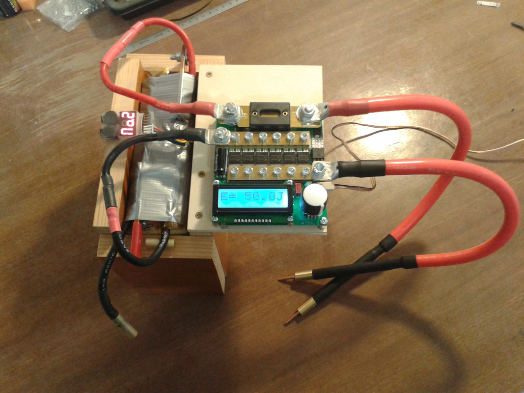
…laser-cut housing for the kWeld system. I have just finished adding the respective section in the system’s assembly manual ...
Cheers
Frank

I’ve had a look at your kWeld ultracapacitor module.
Have you given up on the HP DPS-800GB Server PSU option?

No, I’m just doing the capacitor and the charger modules sequentially. Despite the fact that the charger prototype is working reliably and just needs a PCB redesign, I went with this order because the capacitor module can be used with a regular power supply, but there is not much use of the charger without something to charge.
Cheers
Frank

...
Have you by any chance tested the same capacitors in a 6S1P configuration?

yes I had and didn’t like the result, and then decided to make a spreadsheet to find the best combination and performance/cost tradeoff. I’ve attached it here in case you want to play with it. (It’s not accurate up to the last percent, but it is good enough to compare different setups.)
Cheers
Frank

For those interested, the spreadsheet from Frank is here:
View attachment Usability estimations.xlsx

Could two boards, as designed, be connected in series to power the welder using a 12V power source?
...

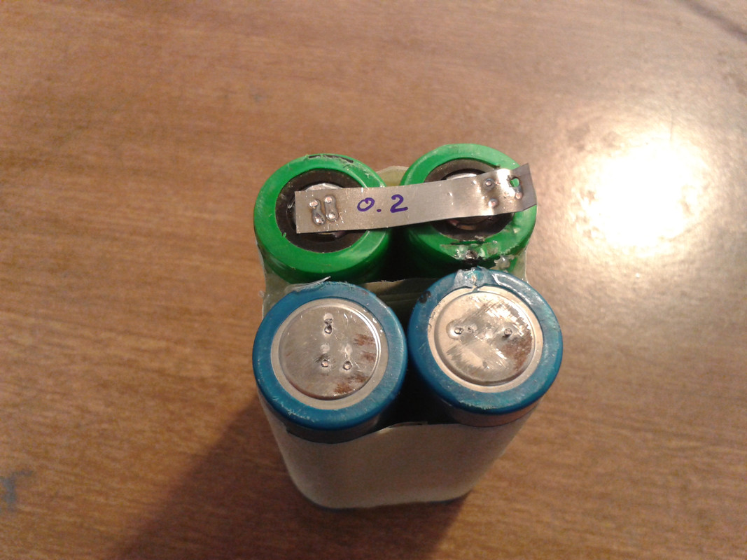
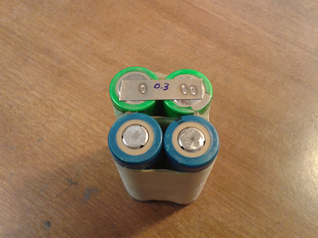
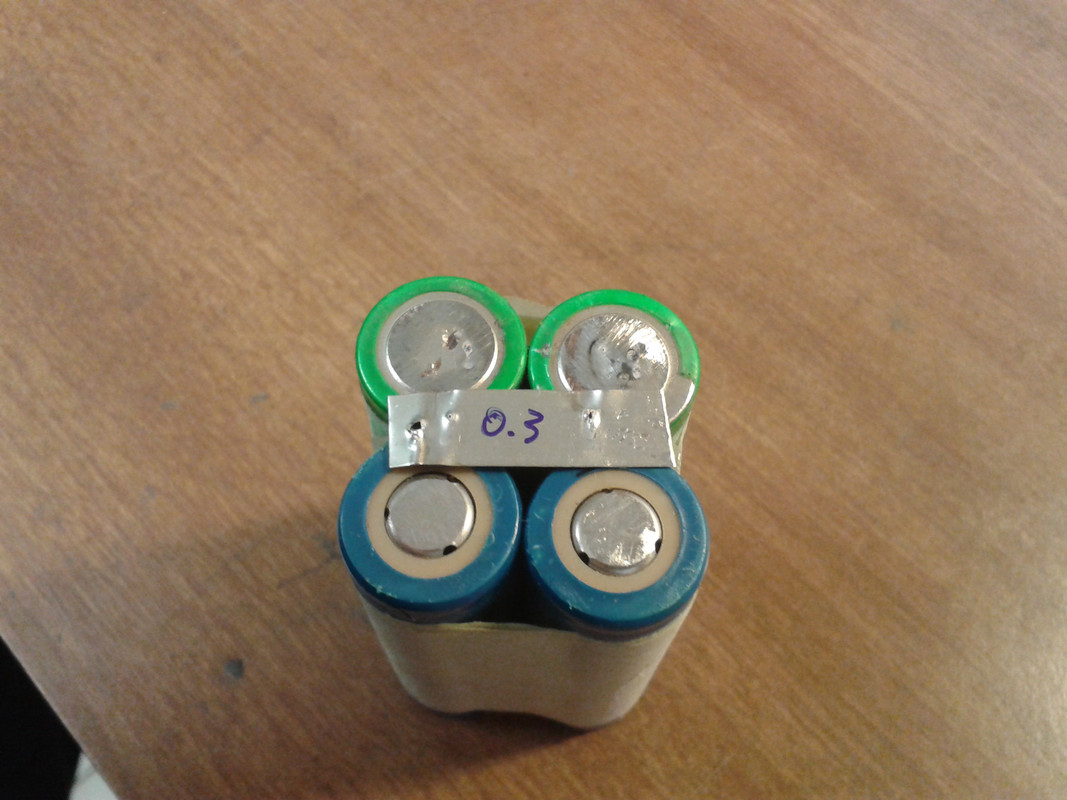
I plan to make a variation with 5S2P that will be 12V capable, if there is enough interest in that. I didn’t go for this in the first place because that adds another ~50€ cost, and the one that I am doing now will likely be good enough for up to 0.3mm pure nickel.
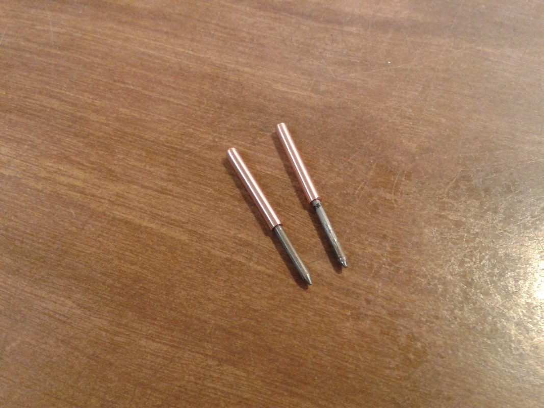
The comfort zone for kWeld is 1500A, with as little voltage as possible (that reduces the likeliness of arcing and improves electrode lifetime)
Your calculations and conclusions are all valid, and your 6S1P conclusion is exactly the reason why I didn’t go in this direction. Your 6S2P variant is certainly related to putting two kWeld-cap boards in series, even though I think that it is a bit overkill, I am sure that you won’t have any compromises with that. I would recommend also testing them in parallel, because that will significantly reduce their losses, which again improves the available repetition rate and their lifetime.
Cheers
Frank

Frank, thank you for your detailed response. It is greatly appreciated.
For welding, for me and most other people, 3S2P is more than enough. With the spreadsheet that you provided, I certainly see all the benefits and completely understand your choice. For your welder, it is clearly the way to go and a much better option than stressing a battery. I hope to be welding 30AWG and 40AWG thinned copper wire to 18650s and from what I have read, I should not need many joules and will I likely be focused on the lower settings.

A peak of 8.1V limits usability to purposes below that threshold,

The option to increase to 6S allows for even more purposes such as: boosting a car with a low battery (very common in cold climates), protecting a 12V battery on a UPS from sudden demands (two boards in series for a 24V UPS and four in series for a 48V UPS),
To place between a solar panel and the MPPT solar controller to reduce voltage fluctuations flowing into the controller,

If I understand correctly, a 6S board could always be charged to only 8.1V for welding but would have many other uses when not welding easily justifying the additional cost.
Nothing better than a tool with multiple purposes that you can use daily :)


I can follow all your arguments, except one. Why would it make sense to make a dedicated 6S2P module, when someone can buy two 3S2P modules and wire them in series. The only benefit that I can see is that an optimized 6S2P module could be made a bit smaller, and I think that I would not be able to offer that at a significantly lower cost. Maybe 180€ instead of 2x100€. And there is a negative aspect of an optimized 6S2P version: you cannot easily mount two 120mm fans. And I don’t think that it is a limitation to have two loosely coupled boards, because housing them properly is a must anyway. You don’t want to accidentally short them. If you do that with your wedding ring, you’ll likely be losing a finger. I keep removing all jewelry before starting to work with them ;) What do you think about my rationale?
Cheers
Frank

Good point Frank!
If you do not see any detrimental issues with wiring these in series, please disregard my request.
The more I think about it, the more I realise that combinations of 3S and 5S boards provide even more flexibility and target voltages.
For instance three 5S modules and two 3S modules wired in series (56.7V) would suit for a 48V UPS that charges at +-54.7V.
One question please. Does the balance feature work at all voltages or does it only activate at 2.7V to prevent overvoltage?

thanks for the fruitful discussion, much appreciated and certainly helps me with doing the most reasonable steps.
I think series wiring two 3S2P will add another 200uOhms, but that should be okay.
The balancer is actually a real balancer, unlike what you get normally (2.7V limiters). It starts working at around 4V, and balances the cells to within +-50mV (target value to be revised). The principle is quite easy. If a cell exceeds (Vtotal * 0.346), then being discharged through 15 ohms until that condition disappears (with a small hysteresis).
Cheers
Frank

...
I just had a look at the joules loss in capacitor per pulse when wiring two boards in parallel using your spreadsheet. Wow!
The difference between parallel and series is really amazing. I can’t understand why but I’ll research it to try to understand.
50 joule weld = 56.25 loss, therefore only approximately 6.25 joules lost in heat?
You should be able to run that all day even without a fan!
PS – I expect that you are probably working on a laser cut housing for these. In order to save on the shipping, I’ll wait until those are available but then I’ll absolutely take two capacitor banks from you.


I haven’t started a housing for the ultracap module yet, but as the power density of it is really high I agree that this is mandatory. I’ll start that as soon as possible.
Frank
 
Endurance testing has finished after 10,000 pulses, and the capacitors held up very well! Here is how the weld current developed throughout the test. The starting current with fresh cells is 1250A. I have extrapolated the curve, and it would hit the 1000A mark after roughly 40,000 pulses. This is at full load and running the capacitors at a permanent temperature of approx 55°C (25°C ambient temp).

guesses-on-what-i-am-attempting-here
 
[/quote]
I know what you mean :wink: If you're quick and have the right tools, then it can be done in less than one hour.
[/quote]

Well, it took me a little longer than that so I have no bragging rights :(
Much longer! Having said that, it was fun the whole time :)

I ran into a couple of delays that I want to share as it may help others.

It turned out that I had a 6mm crimper but not the 5mm. Oops!
I compromised by wrapping the fitting with a nickel strip to make up the 1mm and after some trial and error that worked really well. No need to shop for a 5mm and delay the project :)
IMG_20180413_091512~01.jpg
IMG_20180413_091650~01.jpg
IMG_20180413_091748~01.jpg

With the electrodes, my batch of XT150 fittings only had about 3mm available so the first two attempts sheered at the elbow. On my third and fourth attempts, I moved the crimper away from the elbow capturing only about 2mm, used less crimping pressure and that worked quite well. I had four so I just made it and moved on.
View attachment 3

The instructions were very good and very detailed. Of course, I made a couple of changes. One was in regards to the XT150. I decided to install one narrow black male (brass female) and one wide red female (brass male) on the welder to ensure that it cannot be connected with reverse polarity to make them similar to Anderson Powerpole connectors. I don't like having to install the housing and committing to it before crimping, I don't like that I can't change the housing upon making an error but I do love how small these are.
484715627_615.jpg

Wrapping the connectors in Kapton tape is ingenious. That worked really well. An elastic band on the plier handles was also very helpful. I used one pair of pliers and a hole in a piece of plywood to solder. I also used Kapton to hold the housing away from the solder joint.


I don’t have the recommended battery or capacitor bank so I considered framing this unit and hanging it on my wall as it is a “work of art”. Great job with the design Frank but it’s more fun to play with it so here are some results with what I had kicking around for anyone interested.
5.0 Ah SLA = 175 Amps
9.0 Ah SLA = 368 Amps
18.0 Ah SLA (2 – 9.0 Ah in parallel) = 617 Amps – This is already enough to make some decent welds at 10 Joules but far from the recommended.

I don’t want to pull my car battery so I built a 2S14P using 18650s. Please note that these are high drain tool cells and not laptop cells.
This resulted in 640 Amps so still far from the target 1,500.
5 Joules to 12 Joules took between 6.31 and 16.96 milliseconds and resulted in very solid welds.
Enough to get my feet wet.

If anyone has any suggestions in regards to an alternate pack size, I am all ears. If not, I will likely add more cells or try a similar quantity as a 3S pack (maybe 3S10P).

Here is a photo of the assembled unit.
IMG_20180414_203117~01~01.jpg
 
tatus1969 said:
Endurance testing has finished after 10,000 pulses, and the capacitors held up very well! Here is how the weld current developed throughout the test. The starting current with fresh cells is 1250A. I have extrapolated the curve, and it would hit the 1000A mark after roughly 40,000 pulses. This is at full load and running the capacitors at a permanent temperature of approx 55°C (25°C ambient temp).

guesses-on-what-i-am-attempting-here

That sounds great! Definitely more than I'll ever need.
Can't wait to get mine.
 
Alcus said:
I ran into a couple of delays that I want to share as it may help others.
...
Here is a photo of the assembled unit.
Thanks a lot for sharing that, much appreciated!
 
Really impressive work! The website says all units are sold out... Do you know when new ones will be available for purchase? Looking forward to buy one.

Also, it would be really cool if the welder would send out the measured data over a serial port after each weld. That way one could plot it with a python script or similiar and might see differences between materials, batteries, probes... and would be nice eye candy too. Just a thought.
 
sorg said:
I am also interested. Whel will you refill your shelves ?
Regarding the welder, I have placed an order of electronic modules last week. I am waiting for a definite date from my electronics assembly firm, they are purchasing components right now and it depends on availability/lead time of those. If there are no stock shortages, I expect to receive material in 4-5 weeks from now. Hence, I will be able to begin selling the kits as pre-orders every day.

Regarding the capacitor modules, I have completed redesigning the board and will order boards and component of a first batch this week. But this project has second priority, so I might not be as fast.
 
Back
Top