At the end of the day, you need to assess you comfort/skill level with these various approaches. It may be that a mechanical solution will be the most doable for you.
Anyhow, to finish up a few details on the Option 1 solution:
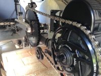
As mentioned above, Kepler reported that the BBS PAS sensor was 24 pole with 2-wire quadrature encoding (two streams of pulses slightly offset so the controller can tell both rpm and direction). The
Grin mini PAS_24P is also 24 pole with the same encoding. Justin reports that although rated for 10V for use with the CA3, it will work fine on 5V which is what you need for the BBS. I mic'd one up and it's 5mm thick - a little fat so you might have to clearance the inside of the crank to fit it.

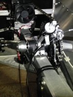
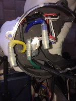
Here we see in one of Kepler's images, a hookup of the BBS PAS sensor to an ebike tester. This shows a standard JST-SM-4M connector and gives us the pinout. We see the same pin order and some color coding in
a shot from a vendor for a replacement BBS sensor part.


So, it remains to hook these together with a little adapter cable that would look like this:

So the plan would be:
- Open the BBS case (see many YouTube HowTo videos)
- unplug the internal PAS sensor from the controller
- Either
- drill a hole in the bottom or rear/downward in the case
(attach the pins to the cable for the inside connector but don't add the plastic shroud until after you thread the pins through the hole) OR
- use a small round file (chainsaw file or similar) to file a small D shaped notch in the lower case edge
(this is handy since you just plop the finished cable into the notch.)
- fabricate and route the adapter cable so there's about 8" or so external to the case
- sleeve the adapter cable with a layer or two of heatshrink where it contacts the case.
- plug the adapter into the controller and button up the case, sealing it with RTV where the cable runs through.
- power the controller and check the +5V/GND pinouts on the external adapter connector.
- plug the Grin cable into the adapter cable
- Spin the cranks to see if PAS kicks in. If it detects reverse pedaling instead, reverse pins 3 and 4 in the adapter cable external connector (Dir and RPM).
Correcting pinouts on the external adapter connector is pretty easy: press the wire into the plastic shroud to relieve pressure on the tang, then using a small flat blade screwdriver, press in the tang on the side of the connector. Holding the tang depressed, pull out the wire with connector attached. Use a small pointy object like a compass point to press into the side of the pin opposite the tang to lift the tang outward and restore its holding ability. When reinserting the pin, the tang goes to the side of the shroud hole with the little square notch. Easy-peasy.
You can get a bag of JST connectors and a JST crimper from Grin. Since the PAS sensor has miles of cable, you can start by just cutting off the connector then cutting off a foot to use as the adapter cable, then you can shorten things as you see fit and attach new connectors to the CA PAS sensor and both ends of the adapter cable. I'd get a spare sensor while I was at it so you have an unmodified one to test with (above) before you bother to shorten and put a connector on the 'tidy fit' one. If you don't feel comfortable fabricating the adapter cable, you can probably get an ES member in AU to do so and mail it to you.
With the same number of poles and no extra electronics, this should leave the BBS performing normally. You can restore it to stand-alone operation by removing the adapter cable and plugging in the internal PAS sensor. As I said above, I have no experience with these motors, but this PAS sensor stuff is pretty generic so this mod should work fine. It's actually quite lucky that Grin just released this new PAS sensor for the CA3 - I'm unaware of any other PAS sensor that sends the required quadrature encoding.
Anyhow, that's about all I've got on that scheme - hope you find a solution that works out for you.