End turns bad?

kiwifiat said:
Alan B said:
Clearly there is a lot of confusion about this topic across the web, there are similar discussions on the net that don't end in clarity. I have done many, many searches and not found a good explanation of why parts of the turns on a tooth in a BLDC core are not contributing to torque. Even a proper definition of exactly what is, or is not included in the end turns is in absentia.

I do agree that the conductor that leaves the tooth and ventures across to the next tooth is not going to provide useful flux to the tooth. Clearly that is an "end turn" and does not contribute to "useful flux". So if that's how "end turns" are defined, then I'm good with that. If somehow part of the wire wrapping around the tooth itself is discounted, I'd like to see a precise reason why.

The force generated on a conductor of length l with current i in a field of strenght B is given by F = ilBsinϕ when ϕ is 90° sin90 = 1. That situation is applicable to the turns in the slot and thus slot turns produce maximum contribution to torque production. The "end turns" are at ϕ=0 with respect to B and since sin0 = 0 there is no force generated. This fact is easily verified experimentally. If you can accept this verifiable fact it should be possible to accept that end turns do not contribute to torque production. To say they are bad is a stretch, plainly they are a necessity. End turns add inductance which is good for controllers, they also help dissipate heat and add to the heat capacity of the motor which is also a positive. As Luke points out end turns are outside the air gap and regardless of their angle with respect to B no force is generated. That is to say that force is generated only by the cross product of stator and rotor flux in the air gap. Luke has done this experiment and given that I did something similar in a physics lab many decades ago I have every reason to trust his reported results. That is the great thing about science, if you don't beleive do the experiment.

If the proof is in the pudding then every paper I have ever read that derives sizing equations from first principles and then goes on to design,build and test said motor the results have without exception agreed closely with those forecast by the sizing equations. Given that some of the brightest minds ever to grace planet earth have contributed to the collective knowledge of humanity in this field I have yet to see one reason to doubt what I read in text books, IEEE papers or doctoral theses( I had to google the plural of thesis) especially when I have verified a number of the fundamental laws first hand.

This explanation seems to ignore the effect of the high permeability core material. So it falls short of fully explaining the situation we are trying to understand. I think we have also seen direct calculations that show when there is a high permeability core the wires are no longer receiving the dominant forces, the forces act across the gap on the core directly. So the directions and angles of the conductors are removed from the dominant force equations, the stator is effectively a bar magnet at that point and the forces should all be derivable from a bar magnet equivalent of the stator tooth at that position and strength.

All the wire turns are out of the air gap in our BLDC motors, only the core and magnet poles are at the gap. The turns and current only serve to align the magnetic domains in the stator tooth which in turn produces the dominant flux. The flux from the wires alone, in absence of the core is at too great an airgap (and too weak without the magnification of the permeability) to have significance in the torque production. The mode of operation of this BLDC motor appears to change when high permeability materials are introduced into the system. This is a different motor operating on a different principle than a coreless model.

I have no reason to doubt these examples which you cite, however I have seen none of them that describe the effect of the core, and how the B field at the gap, which now comes primarly from the stator magnetic domains having been aligned by the field from the turns (and not from the turns themselves), knows anything about the directions of currents in the wires wrapped around the tooth anymore.

If any of these examples cover the complete situation and discuss the how the core materials interact with the windings and the motor poles in detail please specifically cite them, that would be of great value to this discussion.

Thanks!
 
Electric Motors and Drives - Austin Hughes - Chapter1, Page 18 (My emphasis in bold).

The final question relates to the similarity between the set-up shown in Figure 1.10 and the Field patterns produced for example by the electromagnets used to lift car bodies in a scrap yard. From what we know of the large force of attraction that lifting magnets can produce, might not we expect a large radial force between the stator pole and the iron body of the rotor? And if there is, what is to prevent the rotor from being pulled across to the stator? Again the affirmative answer is that there is indeed a radial force due to magnetic attraction, exactly as in a lifting magnet or relay, although the mechanism whereby the magnetic field exerts a pull as it enters iron or steel is entirely different from the ‘BIl’ force we have been looking at so far. It turns out that the force of attraction per unit area of pole-face is proportional to the square of the radial flux density, and with typical airgap flux densities of up to 1 T in motors, the force per unit area of rotor surface works out to be about 40N/cm2. This indicates that the total radial force can be very large: for example the force of attraction on a small pole-face of only 5x10cm is 2000 N, or about 200 Kg. This force contributes nothing to the torque of the motor, and is merely an unwelcome by-product of the ‘BIl’ mechanism we employ to produce tangential force on the rotor conductors. In most machines the radial magnetic force under each pole is actually a good deal bigger than the tangential electromagnetic force on the rotor conductors, and as the question implies, it tends to pull the rotor onto the pole. However, the majority of motors are constructed with an even number of poles equally spaced around the rotor, and the flux density in each pole is the same, so that-in theory at least-the resultant force on the complete rotor is zero. In practice, even a small eccentricity will cause the field to be stronger under the poles where the air-gap is smaller, and this will give rise to an unbalanced pull, resulting in noisy running and rapid bearing wear
.
 
kiwifiat said:
That is the great thing about science, if you don't beleive do the experiment.

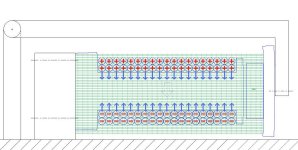
By all means let's devise an experiment. Here's my first attempt:junk.jpg

The iron core (stator) is solidly fixed to the ground. Immovable. The magnet (rotor) is attached to a hinged arm.

So, when the current (red) flows through the coil, in the presence of a magnetic field (green). Lorentz forces (blue) act upon the conductors of the coil.

First problem. the physical forces balance out. Hm.

Second problem: If there is, say as a result of manufacturing differences in the core or coil, a net imbalance in the Lorentz force generated; represented here by the shadowy purple arrow -- it could face either way -- then how does a physical force acting in that direction get transferred to rotate the magnet?

Even if Newton's 3rd were applicable, it says "equal and opposite", not displaced sideways by some unspecified & yet variable distance.

Of course, even if you arrange somehow for the Lorentz forces to not cancel out, this rig will not definitively prove that they are acting on the magnet, because the simple, clearly defined interaction between the magnetic pole created at the right-hand end of the core as a result of Faraday induction, will seek to attract or repel the magnet.

How are you going to preclude that stronger force? so that you can measure the spooky-at-a-distance re-re-reaction of the magnet to the Lorentz force acting in the wrong direction some distance away.

Quite frankly, I cannot believe that we're still discussing this 6 pages in.
 
Miles said:
Electric Motors and Drives - Austin Hughes - Chapter1, Page 18 (My emphasis in bold).

The final question relates to the similarity between the set-up shown in Figure 1.10 and the Field patterns produced for example by the electromagnets used to lift car bodies in a scrap yard. From what we know of the large force of attraction that lifting magnets can produce, might not we expect a large radial force between the stator pole and the iron body of the rotor? And if there is, what is to prevent the rotor from being pulled across to the stator? Again the affirmative answer is that there is indeed a radial force due to magnetic attraction, exactly as in a lifting magnet or relay, although the mechanism whereby the magnetic field exerts a pull as it enters iron or steel is entirely different from the ‘BIl’ force we have been looking at so far. It turns out that the force of attraction per unit area of pole-face is proportional to the square of the radial flux density, and with typical airgap flux densities of up to 1 T in motors, the force per unit area of rotor surface works out to be about 40N/cm2. This indicates that the total radial force can be very large: for example the force of attraction on a small pole-face of only 5x10cm is 2000 N, or about 200 Kg. This force contributes nothing to the torque of the motor, and is merely an unwelcome by-product of the ‘BIl’ mechanism we employ to produce tangential force on the rotor conductors. In most machines the radial magnetic force under each pole is actually a good deal bigger than the tangential electromagnetic force on the rotor conductors, and as the question implies, it tends to pull the rotor onto the pole. However, the majority of motors are constructed with an even number of poles equally spaced around the rotor, and the flux density in each pole is the same, so that-in theory at least-the resultant force on the complete rotor is zero. In practice, even a small eccentricity will cause the field to be stronger under the poles where the air-gap is smaller, and this will give rise to an unbalanced pull, resulting in noisy running and rapid bearing wear
.

Magnets to not just attract or repel face to face. Place a magnet under a piece of glass north pole uppermost. Forcibly position the North pole of another magnet face down directly above it. Let go. It will jump up, but it will also move sideways.

Now modify the experiment so that you constrain the magnet from moving up or down:junk37.jpg

Now, every time you use the stick to try and move the top magnet in line with the bottom one, it will move away. Sideways! Arrange the poles to attract, and they align by moving sideways.

Make one magnet an electomagnet that you can reverse the polarity at will, and attach the other magnet to a hinge so that its pole face rotates past the face of the fixed electromagnet, and you have a one tooth/one pole motor.

Think about why BLDCs have non-matching numbers of poles and teeth. A pure lorentz force motor (like an airgap coil motor) doesn't need (have) that constraint.

Think about how you determine the correct phasing for BLDCs. At any given positional relationship between the poles and magnets, one of the possibly next phase excitements will cause it to move in the desired direction, but the other will try to move it in the opposite direction. With the correct next phasing being determined by that which creates a net balance of attraction and repulsion that moves the rotor in the desired direction.junk38.jpg
 
Miles said:
https://www.edge.org/conversation/paul_davies-taking-science-on-faith

Update: sentence removed.

I followed the link, I saw the word "god", I didn't read.

I was not (will not ever) talking about religious faith; that's a side discussion that is the very last thing this thread needs :)
 
Buk___ said:
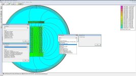
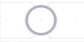
But, my simulation of your hot-rodded BionX'D just completed, with the upshot that at 20A phase current, the total losses from the tooth & hub laminations, back-iron and copper, at a conservative 1600hz, are: Tadah! A whopping great 5.5412W of waste heat per tooth, for a total of 465W!

Could that be why it kept overheating?

Care to guess what they are at 50W/phase?

Just to complete the picture, the answer is 27.8851W of losses per tooth * 84 teeth = 2.34 kW at 50A.


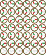
junk39.jpg
 
Buk, i guess if luke or somebody else does an experiement which would proof the effect of endturns, you still would not trust this person as you don't do other smart motor engineers who have written documents and books about that.
You really don't think that one of them could already have done such eperiment?? :wink:

It seem, as you mixing so many other things into this thread, that you don't look for a real scientific answer to your question, but rather to boast with your uber knowledge to gain fame. Sorry, but thats the way i see it.

PS: the D-motor did not overheat due to switching losses like you calculated (which was in my setup only around 1/3 of the 1600Hz), it was overheating at high load probably caused by a large drop in kT.
And it is nice that you bother with the D-motor doing calculations etc, but it doesn't belong into this thread which applies also the quotations from my thread.
 
madin88 said:
Buk, ... you don't look for a real scientific answer to your question, but rather to boast with your uber knowledge to gain fame. Sorry, but thats the way i see it.

What possible fame could a (deliberately) anonymous handle gain me?

I do not have "uber knowledge", I have questions. Anomalies (including this one) that defy my attempts to resolve. I raise them here because I expected to have those anomalies quickly resolved by the considerable expertise here.

But saying something is so, nor quoting someone else saying it is so, is not scientific. And nobody has yet produced one iota of evidence for how Lorentz force arising as a result of the interaction between the electric field in a conductor attached to a stator, and the local magnetic field, could possibly displace that force sideways to cause it to act upon the rotor.

I modeled the BionX'D (long before this thread was ever started) because your thread is one of a handful here that provides enough information -- actual measurements, and where they are missing, close-up, in-focus photographs from which accurate measurements can be extracted -- to allow me to model a real-life working motor and compare the simulators results with published data.

I referenced it here because I was interacting with you, and I thought it would have more resonance to talk in terms of something you have real-world experience of.

To me, it is easy to see how the current situation, vis-a-vis what I consider to be the misapplication of Lorentz force theory to BLDC motors has come about. Any of the many types of motor that use drum-wound coils on rotors, or even the squirrel-cage type rotors, are all, predominantly if not exclusively, powered by Lorentz forces.

But they all have 3 significant difference from BLDCs:
  1. The Lorentz force generating coils are in the rotor not the stator.
  2. The two sides of each turn of coil are on opposite sides of the axis of rotation, not the same side.
  3. The stator field, whether from PMs or generated by stator coils, is uniform across the diameter of the motor, not alternating around the circumference of it.

Which means that in this textbook simple motor:
file.php
, the Lorentz forces acting on the two sides of each individual turn, acting in opposite directions because of the direction of the current flow around the loop, and on opposite sides of the axis of rotation, act in concert to rotate the rotor.

And it is easy to see how that simple motor can be expanded to add more conductors radially and in each slot to produce a useful brush-commutated motor:LorentzForceMotor.jpg

And (so I read) some few years ago, that type of motor dominated. Then BLDCs started a revival; books were updated to mention them as they were the rising thing; but few people looked at how the basic theories that work so well for brushed motors (and other similar types) cease to make sense when applied to them.

When you:

  1. Move the coils to the stator where Lorentz forces can no longer act directly on the rotor.
    Any Lorentz forces now act on the stator not the rotor, and there is no mechanism electrical, mechanical nor magnetic, to transfer them to the rotor.
    .
  2. Wrap the coils around the core material between pairs of adjacent slots, rather diametrically around the motor.

    Now the opposing Lorentz forces created by the current travelling in opposite directions in the two axial sides of each turn, and on the same side of the axis of rotation, exactly balance each other out. Even if you could transfer them to the rotor, the net force would be zero.
    .
  3. Have alternating polarity magnetic fields around the circumference of the motor.

The two types of motor may look superficially similar; but in reality, they are starkly different.

Like I say, it's easy to see how the situation arose; what I wasn't expecting was that no one here (Alan B excepted) seems prepared to apply their own logic to analysing this, rather than just harking back to the books. Perhaps the only reason I see it, is because I wasn't formally trained in the field, so I don't have the historical baggage of that education; I'm free to look at it from a pure "how could that possibly work" perspective.

Given the hostility, and attempts to brand me a 'idiot' (or worse) by a few, what type of 'fame' am I accumulating in my anonymity? And what good could I possibly derive from it?

A few things have sustained my conviction to this thread:

  • Alan B found references to other people asking the same question.

    I did find a blog piece by one guy who touched on it, but then couldn't find it again.
    .
  • If what I was suggesting was entirely without reason -- say I was claiming that electric motors ran at their most efficient when riding along lay lines(*); or something equally ridiculous -- then nobody would be bothering to argue with me.

    (*Cue Pavlovian response from the irritants.)

    The fact that a few people are continuing, suggests (to me) that I've at least caused a smidgen of doubt to creep in.
    .
  • I have spent an inordinate amount of time trying to make Lorentz force calculations describe (simulations of)real-world BLDC motors; and they don't. Not even close.

    I have a certain amount of confidence in my own math; and a considerable amount of confidence in the simulation software; and I have modeled a variety of examples of real-world BLDCs to greater or lesser degrees of accuracy, and whilst I can get a pretty convincing torque profiles that match up to published data using a weighted stress tensor, if I calculate the Lorentz forces for those simulations, they are effectively non-existent.
    .

I apologise if my using data derived from your thread to try to make my point in this one offends you. If you have any responses to my questions about your motor above, then I'd be more than happy to respond to them in your thread if you find that preferable.

I'd love to pursue refining my model of the BionX'D with your help at some point; but it won't be right away and the sheer size and complexity of the model means each run take days, and I have limited resources. (I'd be more than happy to share the model with anyone who feels like installing FEA to run it.)
 
Miles said:
More misinformation :) http://web.mit.edu/first/scooter/motormath.pdf
From page 4 of the pdf:
The maximum torque is produced when the active teeth are right between two magnets,
This could give a differnt sight to the things. At least i wasn't aware of this. I thought the max force is if the magnet is exactly above the teeth.
 
That's an interesting MIT paper, I found it last night. I haven't had a chance to really understand it. And I found the mpoweruk paper this morning. Good work.

One problem is that the poles and teeth intentionally never match all around, so each tooth's relationship will be different.

Why is it that virtually all descriptions of BLDC motor operation never mention Lorentz and always talk about pole attraction/repulsion? The above mentioned paper is an exception, which is rare.

I think we have to figure out how to describe BLDC operation in terms of either approach. Both must be correct and equivalent, at some level.

Similar to understanding current flow as conventional current, or actual electron motion.
 
Buk___ said:
...
But they all have 3 significant difference from BLDCs:
  1. The Lorentz force generating coils are in the rotor not the stator.
  2. The two sides of each turn of coil are on opposite sides of the axis of rotation, not the same side.
  3. The stator field, whether from PMs or generated by stator coils, is uniform across the diameter of the motor, not alternating around the circumference of it.

Which means that in this textbook simple motor:
file.php
, ...

1. In the diagram rotor and stator are not specified. Just the force. And that force acts against the field (Newton's 3rd). So if one nails down the magnets, as you assume, the coil rotates. But nail down the coil and the magnet assembly rotates.

2. This is s simple diagram to explain a principle. The coil sides are at opposite sides of the axis of rotation because a 2-pole example is used. The coil sides are at 180°electrical apart which is 180°mechanical for a 2-pole machine. The coil span or pitch is 180°m. For a 4-pole the coil pitch is 90°m. For an 8-pole, 45°m apart.

Since the number of slots is often unequal to the pole count, the actual coil pitch is not necessarily exactly = 360°m/poles.

And due to the nature of the simple diagram, realize that the armature would contain a ferromagnetic core, there would be back iron, flux would be radial crossing the air gap and the forces would be tangential.

3. Again due to the simple nature of the example diagram, the commutation method is not shown. But it could well be electronic instead of mechanical (brushes), which is the same as the armatures in bldc. And if the coil was stationary makes the example a bldc, doesn't it?

major
 
madin88 said:
From page 4 of the pdf:
The maximum torque is produced when the active teeth are right between two magnets,
This could give a differnt sight to the things. At least i wasn't aware of this. I thought the max force is if the magnet is exactly above the teeth.

The simulator shows that too. And (IMO) it is easy to understand.

With a tooth directly between two magnets (with opposite magnetic poles), whichever polarity the tooth is excited with, it will be repelling one magnet and attracting the other.

If you took a motor and disconnected all but one tooth, when you excited that tooth, the nearest magnet of the opposite polarity to the excitement would rotate to align itself, and self-center directly above the tooth. Wait a second or to for it to settle, then reverse the polarity in the tooth, and that magnet will be repelled away and an adjacent magnet will self-center. They will self-center because that is the point of lowest 'tension' (short path) for the flux lines between them. (Their coenergy is minimised.)

Which way the rotor will move from the centered magnet when the tooth's polarity is reversed, is anyone's guess. It might move one way, one time and the other, the next. And the more accurately matched their strength, and the positioning of the magnets is, the more closely the odds of moving in either direction will get to 50:50.

That's why we use three phases, and only excite two at a time; it allows us to dictate the direction of rotation, once we've established a known relationship, by choosing to excite whichever combination of phases next, as will produce torque in the desired direction.
 
major said:
if the coil was stationary makes the example a bldc, doesn't it?

major

No. I refer you back to my modifications to the book diagram from page 3 of this thread. Bearing in mind that the small coils I've added each side need to be turned through 90° so that their centres align with the magnets; this more closely resembles an outrunner BLDC:

file.php


Note how the Lorentz force on two of the conductors in the small loops on opposite sides of the axis of direction, cancel each other out. No matter how many more full turns you add, only the single, half-turn each side will act to generate torque.

Now put a core through the middle and add a head on each tooth, and you've moved the coils far enough away from the magnets that the 1/R^3 rule means they no longer generate significant amounts of Lorentz force; and what they do generate, (mostly) self cancels.

However, view those small loops as solenoids, with the cores providing a low reluctance path from the coils to the face of the heads, and you now have very dense flux in the air gap; and very strong attraction and repulsion (cross-linking) between those solenoids and the magnets.

Fix the coils and allow the magnets to rotate and then you have an outrunner BLDC.
 
Buk___ said:
major said:
if the coil was stationary makes the example a bldc, doesn't it?

major

No.
... >snip<
Fix the coils and allow the magnets to rotate and then yuo have an outrunner BLDC.

First no. ... Then yes. ????

Why isn't that subject diagram a 2-pole BLDC?
 
major said:
No.
... >snip<
Fix the coils and allow the magnets to rotate and then yuo have an outrunner BLDC.

First no. ... Then yes. ????

Why isn't that subject diagram a 2-pole BLDC?

It's all in the >snip<.

You start with flour; add yeast and water and salt; kneed, prove, bake; you get bread. If you snip the intermediate stages, you do not prove[sic] flour to be the same as bread.
 
Buk___ said:
major said:
No.
... >snip<
Fix the coils and allow the magnets to rotate and then yuo have an outrunner BLDC.

First no. ... Then yes. ????

Why isn't that subject diagram a 2-pole BLDC?

It's all in the >snip<.

You start with flour; add yeast and water and salt; kneed, prove, bake; you get bread. If you snip the intermediate stages, you do not prove[sic] flour to be the same as bread.

First you say it isn't bldc.
Then you say it is bldc.

What does snip have to do with it?
 
major said:
Buk___ said:
major said:
No.
... >snip<
Fix the coils and allow the magnets to rotate and then yuo have an outrunner BLDC.

First no. ... Then yes. ????

Why isn't that subject diagram a 2-pole BLDC?

It's all in the >snip<.

You start with flour; add yeast and water and salt; kneed, prove, bake; you get bread. If you snip the intermediate stages, you do not prove[sic] flour to be the same as bread.

First you say it isn't bldc.
Then you say it is bldc.

What does snip have to do with it?

You quoted me, saying "No." then "Yes"; but you snipped everything that was between them. (That is the very definition of 'taking stuff out of context'.)

As I said, "it's all in the >snip<"; that is to say, the answer to your question: "Why isn't that subject diagram a 2-pole BLDC?" is all in the stuff you snipped out between my saying "No", then (a very qualified) yes.

If you cannot see that (individual turn of) coils that wrap around from one side of the axis of rotation to the other, are fundamentally different from coils on either side of that axis of rotation, I despair of explaining it.

Given time and the equipment I could demonstrate it physically; in less, but still not inconsiderable, time I could knock up a simulation that would demonstrate it to my satisfaction; but yours...

And to be honest, I'm kind of tired of trying to find new ways to express, what is to me, staring us all in the face. I get that you disagree, repeating it adds nothing. And my repeating my arguments adds nothing.
 
major said:
Fix = secure?

file.php


Electronially commutate, secure the coil and allow the magnets to rotate. Isn't it a 2-pole bldc?

What you would have is an ironless, air-coil motor. Like these. They work, but are quite different from the motors we put on our bikes; at almost every level.

Look around their site, and see if you can find them referring to their motors as BLDCs. They certainly don't fit most descriptions.

They are fine motors; huge power to weight ratios; superb construction. If they weren't so damned expensive they'd make great e-bike motors, but (from what I can gather, they are cagey) they need very special, proprietary, patented and expensive controllers.
 
BLDC = BLAC

PMAC = PMDC

IPMAC= IPMDC

Thin gap motors use geometry to win the specific torque game at the cost of needing some elaborate mechanical support structures to operate.

No voodoo required, magnetics doesn't come to an end somewhere that results in understanding, only a working knowledge through observed related rates between phenomena has been achieved. The same is true for all aspects of physics/science, which so far carries with it only a 100% record of being false expressions of human constructed confusion, as given development of better instrumentation every postulated scientific theory has fallen without exception.
 
Back
Top