End turns bad?

major said:
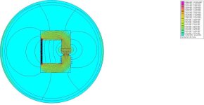
Below there is flux map of a magnetic circuit with an air gap on the right (green line) and a 4 turn coil on the left providing excitation (mmf)

Part 2:

In the following the are further small changes:
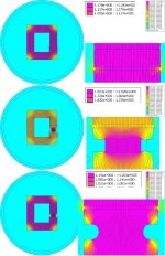
  • I've moved the coil to a position more representative of a tooth. Now the rest of the circuit more resembles the back-iron and other teeth. I've further reduced the size of the air gap to a not unattainable 0.5mm; and I've reduced the thickness of the magnet from 5 to 2.5mm, just to show that you don't need to throw lots of expensive PM into the mix.

    The results show that the maximum field density is almost unchanged at 1.2T and the fringing is further reduced.
    .
  • In the second flux map I've put a radial undercut above the coil and below the face of the tooth.

    The results show the maximum field density has climbed to almost 2T, despite the same size (now smaller) magnet and the same current.

    But, nothings for free. The extra field density is concentrated in the neck of the reduced section, and otherwise unchanged through the rest of the circuit; but now a few of the flux lines are jumping ship and bypassing the constriction through the air.
    .
  • However, in the third flux map, I've eased the constriction a little by radiusing the inner corners. This avoid the worst 'pinch point' and prevents any flux lines from bypassing the reduction.

    The maximum field density is back to 1.2T, but it is much more evenly distributed around the circuit.
    .
  • FInally (separate image), I've reduced the size of the return arm of the circuit dramatically, to make the point about how when the density in the circuit becomes too high, the path of lowest reluctance ceases to be around the circuit, and lines start jumping ship for a lower reluctance route.

There's more; if anyone is interested.

FringingFlux2(reduced).jpg

FringingFlux3.jpg
 
That's very interesting. I don't see where the location of the coil affects the flux map. And how any of that shows any contribution from conductors not passing thru the core. I suspect you're using too low of a current against the magnet strength. Maybe try 200A or more.

Trying to stay focused on end turns, which in this example are the 4 conductors outside, to the left, of the core, perhaps repeat sim 1 or 2 with those 4 conductors moved far away from the core to see that it doesn't alter the air gap flux.

My purpose using this example was to demonstrate Ampere's Law showing that only current passing through the magnetic circuit produces mmf in that circuit.

Anyway thanks for the simulations.

major
 
major said:
... perhaps repeat sim 1 or 2 with those 4 conductors moved far away from the core to see that it doesn't alter the air gap flux.

I'm more than happy to modify the sim(s), but I suspect we are again (still!) talking at cross purposes, in as much as I think you are envisioning a quite different scenario being represented by the original image you posted, to that I was/am envisioning.

To help me understand you, could you post a modified version of that image showing where the motor's axle would run?
 
Buk___ said:
major said:
... perhaps repeat sim 1 or 2 with those 4 conductors moved far away from the core to see that it doesn't alter the air gap flux.

I'm more than happy to modify the sim(s), but I suspect we are again (still!) talking at cross purposes, in as much as I think you are envisioning a quite different scenario being represented by the original image you posted, to that I was/am envisioning.

To help me understand you, could you post a modified version of that image showing where the motor's axle would run?

I'm sorry but I am hindered by my computer equipment, software, internet service and skills. I will see if I can locate an existing diagram to use. In the mean time, go back to the original posted diagram of this core. The green line in the air gap would be on a radius from the axis of rotation relating this to a motor, if that helps you.

This again was a simple example. The motors are double air gap machines with at least two parallel magnetic circuits.

Another thing came to mind when you inserted the PM into the example core. Shouldn't there be 2 magnets side by side in opposite polarity?
madin88 said:
Miles said:
More misinformation :) http://web.mit.edu/first/scooter/motormath.pdf
From page 4 of the pdf:
The maximum torque is produced when the active teeth are right between two magnets,
...

major
 
major said:
Buk___ said:
To help me understand you, could you post a modified version of that image showing where the motor's axle would run?
In the mean time, go back to the original posted diagram of this core. The green line in the air gap would be on a radius from the axis of rotation relating this to a motor, if that helps you.

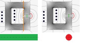
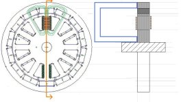
That still leaves two possibilities in my mind for how that image is orientated. The axle could run left to right below the "tooth" (as in green in left image) or front to back (as red in the right hand image)?:junk40.jpg


If it's the left-hand side as I was envisaging, then the righthand side of the C-section with the air gap, represents an axial plane cross-section through a tooth and the stator below the air gap, and through the magnet and rotor back-iron above the airgap.

And everything to the left of the orange dashed line is a dummied-up return path, a substitute for the adjacent teeth and rotor back-iron which cannot be shown in this cross-sectional view because they are in-front or behind the plane of the 2D section.

In order to simulate the flux around the end turns -- and both sets of 4 conductors would be end turns in my scenario -- it is necessary to provide this dummied-up low-reluctance circuit path as a substitute for the adjacent teeth (fore and aft) that the simulator doesn't 'know' about.

Hence the reason I moved the coil around the tooth, and added the magnet.

If however, you are envisioning the right-hand view above, then I cannot make sense of what you were trying to show.

major said:
This again was a simple example. The motors are double air gap machines with at least two parallel magnetic circuits.

Another thing came to mind when you inserted the PM into the example core. Shouldn't there be 2 magnets side by side in opposite polarity?

Not in this (as I saw it) axial plane cross sectional view. There would be another magnet somewhere in front of the screen, and another hiding behind the screen, with all three in-line (ignoring the motors curvature) in this view.

junk41.jpg
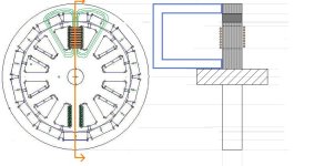
If the left hand part of the above image is a down-axle view of the type of large diameter, narrow (axially short) BLDC outrunner motor typically found in e-bike hub motors.

The copper bars at the top are the "end turns", the (crude) green loops are magnetic circuit(s) for the tooth at 12 o'clock, and the orange line shows where the cross-section is taken, then the right hand side is that axial plane cross-section.

The only way to model the flux around those end turns -- the groups of conductors on both sides of the core -- is in this cross-sectional view, but it presents a problem; no way to show (or model) the the return path for the flux flowing through this tooth, which are not in this plane.

So, to facilitate an accurate model, you add a substitute low-reluctance return path, here shown in blue outline.

And that is what I assumed the drawing you posted, somewhat represented.
 
Buk___ said:
major said:
Buk___ said:
To help me understand you, could you post a modified version of that image showing where the motor's axle would run?
In the mean time, go back to the original posted diagram of this core. The green line in the air gap would be on a radius from the axis of rotation relating this to a motor, if that helps you.

That still leaves two possibilities in my mind for how that image is orientated. The axle could run left to right below the "tooth" (as in green in left image) or front to back (as red in the right hand image)?:junk40.jpg


If it's the left-hand side as I was envisaging, then the righthand side of the C-section with the air gap, represents an axial plane cross-section through a tooth and the stator below the air gap, and through the magnet and rotor back-iron above the airgap.

And everything to the left of the orange dashed line is a dummied-up return path, a substitute for the adjacent teeth and rotor back-iron which cannot be shown in this cross-sectional view because they are in-front or behind the plane of the 2D section.

In order to simulate the flux around the end turns -- and both sets of 4 conductors would be end turns in my scenario -- it is necessary to provide this dummied-up low-reluctance circuit path as a substitute for the adjacent teeth (fore and aft) that the simulator doesn't 'know' about.

Hence the reason I moved the coil around the tooth, and added the magnet.

If however, you are envisioning the right-hand view above, then I cannot make sense of what you were trying to show.

major said:
This again was a simple example. The motors are double air gap machines with at least two parallel magnetic circuits.

Another thing came to mind when you inserted the PM into the example core. Shouldn't there be 2 magnets side by side in opposite polarity?

Not in this (as I saw it) axial plane cross sectional view. There would be another magnet somewhere in front of the screen, and another hiding behind the screen, with all three in-line (ignoring the motors curvature) in this view.
junk41-1.jpg

If the left hand part of the above image is a down-axle view of the type large diameter, narrow (axially short) BLDC outrunner motor typically found in e-bike hub motors.

The copper bars at the top are the "end turns", the (crude) green loops are magnetic circuit(s) for the tooth at 12 o'clock, and the orange line shows where the cross-section is taken, then the right hand side is that axial plane cross-section.

The only way to model the flux around those end turns -- the groups of conductors on both sides of the core -- is in this cross-sectional view, but it presents a problem; no way to show (or model) the the return path for the flux flowing through this tooth, which are not in this plane.

So, to facilitate an accurate model, you add a substitute low-reluctance return path, here shown in blue outline.

And that is what I assumed the drawing you posted, somewhat represented.

Again, the core I showed was to illustrate Ampere's Law not to model exactly a portion of a motor. But in your last diagram the added blue horseshoe best explains it. However the 8 conductors on the left side of the tooth are now passing thru the new path and are productive whereas the 8 conductors on the right side of the tooth are outside this magnetic path (core) and are noncontributing end turns (along with portions of wire connecting the 16 conductors shown. An analogy is the Gramme ring where 3 of the 4 coil sides are noncontributing (end turns).

In that last diagram you show a nice depiction of the parallel magnetic paths (in green). Each path crosses the air gap twice hence double air gap reference before. Another reason it is difficult to use a single air gap example. Also to simulate maximum torque the tooth needs to center between two magnets.

major
 
flathill said:
water seeks its own level

forget rotary motors and just think about a linear motor (unrolled rotary motor)

...

the flux "steering" happens as naturally as water finding its own level,
nothing is actually actively steering the water to reach equilibrium,
nothing is actually actively steering the flux,
balance/imbalance springs from the geometric symmetry/asymmetry
the motor moves in search of balance

I hate to leave a post where someone has obviously put a lot of effort in, unresponded; but no matter how many times I read your post, I cannot visualise what you are describing. (A picture paints a thousand words?)

Equally, without that understanding, I'm not sure from the text what point you are making -- are you in the "end turns are bad" school of thought, or making the case the other way?

Sorry, Buk.
 
End-turns are neither good or bad, they are returning the current path to the slot, that's pretty handy of them to do for us.

End turn windings make a force that balances itself out and the vector direction of the force is perpendicular to the axis that our shaft torque generation happens from.

The motors I used in my ultimate hover time multi-rotor were over half end-turn copper vs slot fill copper (due to being a large flat aspect ratio 'pancake motor'). They were selected based in prop-dynoing everything available on the hobby market that had a shot at spinning a 30in prop.

In EVs I generally run very large phase leads (00awg+), but most OEM motor phase leads are likely equal in R loss if not more than the end-turn related R loss.
 
liveforphysics said:
End turn windings make a force that balances itself out and the vector direction of the force is perpendicular to the axis that our shaft torque generation happens from.

The question really is: do end turns contribute to the torque of the motor; or is all the current they consume through I²R entirely wasted.

I take it (after several readings) from the above piece of tortuous gobbledygook that you are of the opinion that they do not contribute anything to the torque of the motor.

I have two questions:

  1. What is this mysterious "force" that balances itself out?
  2. Prove it? As in, can you provide a mathematical basis for your conclusion? (Amphere, Maxwell, Lorentz, Lenz, Newton, LaPlace...)
 
visualize the flux passing thru the Riemann surface bounded by the coil's turns

I will be not replying further as you are too rude
 
flathill said:
visualize the flux passing thru the Riemann surface bounded by the coil's turns

I will be not replying further as you are too rude

I thought I was perfectly polite to you!?

(Shame though, I wanted to ask you whether you thought that bounded Riemann was meromorphic with respect to the Stein manifold?)
 
Why don't u ask Grigori Perelman

U weren't particularly rude to me but you were to my friends

so I'm done talking to you

Peace out
 
I feel that theoretical discussions and prototype modeling can be very useful, and even fun at times. However...I've seen Lukes work, and when he says that he has dyno'ed two comparative motors and one performed better, I believe him. The fact that I don't understand why (yet), does not change the result.

He has recently been advocating for lower voltages and higher amps to achieve the same result, and such a design paradigm has complex interaction to ponder. Motor design has so many compromises. I suspect the high-Kv / Low-turn-counts that Luke is working with have (as a minor effect) also reduced the "end turn losses", due to the larger conductors having lower resistances over-all.

Years ago, there were discussions about whether it was more efficient to operate at WOT, or...to double the systems' top speed and then operate at half-throttle, but...that was focused on battery range, due to the poor range of the batteries from yesteryear.

I've learned a few things from this thread, and I hope I have contributed some small amount, but...I must confess that the technical parts have now risen above my capabilities. I still don't fully understand end turn losses and the options to address those, but...I have come to regard them as...a necessary evil?...simply a part of the cost of "doing business".
 
Here is a thread from a RC forum that is discussing the same topic:

https://www.rcgroups.com/forums/sho...all-and-thin-Case-in-point-1804-vs-1306/page6

In the thread, there was a peer-reviewed research paper that addresses this topic:
http://www.aedie.org/11chlie-papers/186-amoros.pdf
While this paper is looking at a switched reluctance motor, the effect of the windings on torque would be the same as a BLDC motor.

Bottom line: if the end turns are within the stator core's magnetic structure, they do contribute to the torque.
 
Buk___ said:
I take it (after several readings) from the above piece of tortuous gobbledygook that you are of the opinion that they do not contribute anything to the torque of the motor.

I have two questions:

  1. What is this mysterious "force" that balances itself out?
  2. Prove it? As in, can you provide a mathematical basis for your conclusion? (Amphere, Maxwell, Lorentz, Lenz, Newton, LaPlace...)

If you would be in "who want's to be a millionaire", and you would ask the audience lifeline and they would anwer with 90% for question A, i think you would not trust them, stop and taking the money :lol:
 
Firstly, let me apologise for not getting back to you earlier. I had part written a reply, when a distance memory of something I had read stirred in my brain. It took me a while to to remember where and what, re-read it -- this time trying to understand it -- and then I had to run a bunch of simulations to make sure I'd understood well enough to apply it.

major said:
Again, the core I showed was to illustrate Ampere's Law not to model exactly a portion of a motor.
Understood. I misunderstood your purpose and viewed it in a quite different way to you.

major said:
But in your last diagram the added blue horseshoe best explains it.
I'll get back to that.

major said:
However the 8 conductors on the left side of the tooth are now passing thru the new path and are productive whereas the 8 conductors on the right side of the tooth are outside this magnetic path (core) and are noncontributing end turns (along with portions of wire connecting the 16 conductors shown.

This is where we differ. I see coils wrapped around core, you see them "passing thru". Its a subtle distinction, but one which makes a (IMO) significant difference.

major said:
An analogy is the Gramme ring where 3 of the 4 coil sides are noncontributing (end turns).

I did look that up the first time you mentioned it, and beyond a few photos of some typically impressive Victoriana that didn't show enough detail to understand the principle, I didn't learn much. This time I've persisted longer and now think I get it.

The significant difference I see between that motor and the typical e-bike motors I'm trying to describe, is that the coils wind around the full diameter of the rotor (as most clearly shown in this image:
800px-Drum_Wound_Armature_-_Single_Coil_Example.jpg
.

The current flowing in opposite sides of each turn of coil, are on opposite sides of the axis of rotation, thus, when they cut the same magnetic field, the Lorentz force they generate acts to push the rotor down on one side, and up on the other. Ie. it is a true Lorentz force motor.

In the motors I've been describing the Lorentz force on either side of the same tooth are both on the same side of the axis of rotation, and so their equal and opposite nature means they cancel each other out. (They also act on the fixed stator.)

Something else has to be the source of the torque.

major said:
In that last diagram you show a nice depiction of the parallel magnetic paths (in green). Each path crosses the air gap twice hence double air gap reference before. Another reason it is difficult to use a single air gap example. Also to simulate maximum torque the tooth needs to center between two magnets.

Indeed. A single tooth simulation is useless for deriving any realistic metrics about a full motor; it only serves to explore the how the shape affects the flux in and around the tooth, magnet and airgap. Its simplicity allows me to put more detail -- individual conductors, individually modeled laminates etc -- whilst having the models process in relatively short amounts of time.

Now, back to that "blue horseshoe". For me, that horseshoe was simply scaffolding that served on to facilitate modelling an axial plane cross-section of the tooth. It was intended purely as a substitute for the return path that I couldn't show in this 2D representation. It was meant to not otherwise effect the model.

You believe it does, and on further examination you are correct! Though perhaps not quite in the way you think. (Or more correctly, not quite in the way I think, you think :) I have a bunch of connected simulations that show this, but I need to clean them up, reduce them and describe them. I'll get to it sometime if you're interested.

Now to the product of that half remembered idea, the research and some results that you might find interesting. It involves a big image. I hope the process of reducing its size so the site will allow me to upload it doesn't degrade the details too much when you view it.
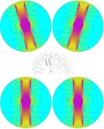
junk42.jpg

First look at the top two circles, and know they constitute a single simulation.

Then look at the partial axial view of a typical bldc outrunner below and picture that the two teeth in the top circles are radial cross-sections of the two teeth mark with green and blue lines.

(It's stretches credibility because the teeth seem oddly long, they are isolated, and the back-iron above the magnets and below the teeth does not appear to be shown. But bear with me.)

There is a mathematical device called a boundary condition, that allows you to connect two otherwise isolated parts of a simulation.

In the case of the top two circles, the upper hemisphere of the left flux map boundary, is mathematically connected to the upper hemisphere of the right flux map boundary. And ditto for the two lower hemisphere boundaries.

That means that the simulator has connected them mathematically, and the force and direction of any flux crossing the upper left boundary, re-enters into the upper right, and vice versa. Ditto for the bottom boundaries. More importantly,it means that when the solver its iterating its calculations, each side is duly influencing the other as it converges to a solution.

Why bother when you could just connect them with material in the normal way. Because it doesn't just work for boundaries that are in the same 2D plane.

That said, now look at the bottom two circles. They look the same except that they are upright, but they are actually not radial cross-sections of two adjacent teeth, but rather axial cross-sections.

That is to say, they are axial cuts through the stator teeth shown by the green and blue lines. Two sections that would normally be one behind the other in an axial plane view.

Normally, these cannot be modeled at the same time because they are in different 2D planes, but by the trickery of boundary conditions, they can be modeled side by side and connected, without resorting to crude scaffolding as represented by the blue horseshoe in my previous post.

That means that the coils shown in both images are the end turns of those two teeth, and the flux pattern (and the magnetic circuit between them) is correct; and significantly, uninfluenced by any scaffolding structures.

And the really significant part about that (IMO:) ), is that it shows that whilst there is a lot of fringing evident around the (ends of the) air gap, with the exception of a local loop-back around the ends of the magnets, every single flux line produced by the end turns, flows through the core and crosses the air gap (producing reluctance torque!).


Most of those flux lines in the core flow around the full circuit -- crossing out the top of the left map, back in top right, down through the magnet and across the air gap in that tooth, before exiting bottom right and re-entering bottom left.

And those few that exit the ends of the teeth (left and right in this view), circle back and re-enter on the other side (above or below) the air gap.

I really hope you find that as convincing as I do. If not, I guess we'll just have to agree to differ :)

Notes:
  • The reason the teeth are so long, is to allow me to make the bounding circles big enough that they do not influence the flux that circles back locally across the air gap, and so avoids 'corrupting' or compromising the model.

    (If it helps, you can think of the extensions to the teeth as my having split the back-iron mid-way between the two teeth and folded it back to put it in the same plane.)
    .
  • Although I call this a "mathematical trick", it is (so I am assured) a perfectly sound mathematical process, and is effectively the same process (periodic boundary condition) that is used when you see only 1/4 or 1/3rd of a motor simulated.

    In that case, the boundary conditions tie the two cut radials of the part motor together, exploiting physical and magnetic symmetries to cut simulation run times
    .
.

As I mentioned, I do have some other stuff pertaining to why I make the distinction between the wire coil motor and (what I now think I must call) 'wound-tooth, salient pole BLDC motors' of the type inset above; in order to avoid further alphabetty spaghetti discussions.

But that's for another day :)
 
madin88 said:
i think you would not trust them, stop and taking the money :lol:

If anyone was offering me me a million dollars for my research, I'd take the money for sure; but that's unlikely as most mathematicians consider my reliance on pictures and words rather than math, makes me little more than a storyboard writer :)
 
Buk___ said:
Firstly, let me apologise for not getting back to you earlier. I had part written a reply, when a distance memory of something I had read stirred in my brain. It took me a while to to remember where and what, re-read it -- this time trying to understand it -- and then I had to run a bunch of simulations to make sure I'd understood well enough to apply it.

major said:
Again, the core I showed was to illustrate Ampere's Law not to model exactly a portion of a motor.
Understood. I misunderstood your purpose and viewed it in a quite different way to you.

major said:
But in your last diagram the added blue horseshoe best explains it.
I'll get back to that.

major said:
However the 8 conductors on the left side of the tooth are now passing thru the new path and are productive whereas the 8 conductors on the right side of the tooth are outside this magnetic path (core) and are noncontributing end turns (along with portions of wire connecting the 16 conductors shown.

This is where we differ. I see coils wrapped around core, you see them "passing thru". Its a subtle distinction, but one which makes a (IMO) significant difference.

major said:
An analogy is the Gramme ring where 3 of the 4 coil sides are noncontributing (end turns).

I did look that up the first time you mentioned it, and beyond a few photos of some typically impressive Victoriana that didn't show enough detail to understand the principle, I didn't learn much. This time I've persisted longer and now think I get it.

The significant difference I see between that motor and the typical e-bike motors I'm trying to describe, is that the coils wind around the full diameter of the rotor (as most clearly shown in this image:
800px-Drum_Wound_Armature_-_Single_Coil_Example.jpg
.

The current flowing in opposite sides of each turn of coil, are on opposite sides of the axis of rotation, thus, when they cut the same magnetic field, the Lorentz force they generate acts to push the rotor down on one side, and up on the other.
...

The image you show is a drum style armature, not Gramme ring. It has 2 of the 4 coil sides productive.

Here is the Gramme ring:

images.png

It has only 1 of 4 coil sides productive.

Gramme ring was quickly abandoned in favor of drum armatures when designers understood Monsieur Ampere's law and were able to double the copper utilization. I mentioned it because it is an example of windings outside of the magnetic path being useless for generation of torque and voltage. Same as end turns.

No insult implied here, but your concept of coil "turns" goes back 100 years or more. "Turns" is just a convenience word so students could visualize coils when the physical quantity of current passing thru the closed magnetic path causes the mmf in that path, as expressed by Ampere's Law. In fact, "ampere conductors" is often used in machine design, especially where they are distributed opposed to the classical solenoid shaped coil. And even more abstract, there is used the term "current sheet" describing the interaction with total or average air gap flux.

After the drum armature image you again stress the coil side positioning (180°m) as being different than your single tooth wound motor. That is only because it is a 2-pole design. The coil sides or coil pitch is made close to the pole pitch of the machine (180°e). The same holds true for your 14-pole motor where coil pitch is 30°m.

I'll get back to your simulations later.

major
 
fechter said:
Here is a thread from a RC forum that is discussing the same topic:

https://www.rcgroups.com/forums/sho...all-and-thin-Case-in-point-1804-vs-1306/page6

In the thread, there was a peer-reviewed research paper that addresses this topic:
http://www.aedie.org/11chlie-papers/186-amoros.pdf
While this paper is looking at a switched reluctance motor, the effect of the windings on torque would be the same as a BLDC motor.

Bottom line: if the end turns are within the stator core's magnetic structure, they do contribute to the torque.

Thanks for the link to the paper, it makes interesting reading; and of course, I'm enamored with their findings :)

It is a shame that it isn't possible (TMK) to apply their findings or methods directly to a normal rotary motor, rather than a linear one; and modeling end turns as hemi-tori works for their test rig, but isn't directly applicable to most normal motors.

Still, it bodes well for there being a way to define the math for the rotary case.
 
major said:
No insult implied here, but your concept of coil "turns" goes back 100 years or more. "Turns" is just a convenience word so students could visualize coils when the physical quantity of current passing thru the closed magnetic path causes the mmf in that path, as expressed by Ampere's Law. In fact, "ampere conductors" is often used in machine design, especially where they are distributed opposed to the classical solenoid shaped coil. And even more abstract, there is used the term "current sheet" describing the interaction with total or average air gap flux.

Hm. I wasn't aware that I had or was using a "concept of coil turns".

My use of the term (and everyone else's on this forum from what I've seen), simply relates to one individual 360° loop (hoop, rotation, twist, encompassment) of copper wire amongst the many ...s (pick a term) that make up a coil. Nothing more than that.

  • Ampere conductors: Not a term I was familiar with; but looking it up I discover it means something quite different to the way I (and everyone else on this forum) use the terms "turn" & "turns"

    Definition: "The product of the number of conductors round the periphery of the winding and the current in amperes circulating in these conductors".

    Eg, n * A

    And it appears to be use exclusively in the context of 3-phase AC induction motors, where another term you keep using "armature" also comes up a lot.

    (eg. In this pdf, the term appears twice:
    1. Once amongst a list of variable definitions, where it is defined as 'ac' and another variable Ts = Number of turns per phase. DIfferent variables for different things.
    2. The second is a title to a graph showing "Ampere Conductors Vs Stator turns per phase"; so again different (if related) quantities.
  • Current sheet: This seems to be used exclusively by astrophysicists and magnetohydrodynamicists (whatever they do).

    It is a purely mathematical abstraction of the type loved by pure mathematicians who seem to have a hatred of the messy discontinuities that plague the real world. Non-infinite conductors; messy, discrete lumps of conductor rather then a nice uniform continuum of potential.
    .

As such, neither alternative fits the usage this purely applied mathemafaker makes of the term 'turn'.

All of which leads me to question why you brought it up. And the only thing that comes to mind, is that it is some kind of in loco parentis retort to my use of the word gobbledygook. True or not, now seems as good a time as any to explain that as it seems to have struck a nerve in some quarters.

The sentence was "End turn windings make a force that balances itself out and the vector direction of the force is perpendicular to the axis that our shaft torque generation happens from."; so let's break that down:
  • End turn windings:
    Winding have end turns; vice versa not so much.
    .
  • make a force:
    "make"?
    What kind of force?
    .
  • that balances itself out:
    Okay. Resultant net force zero.
    .
  • and the vector direction of the force:
    "vector direction", is that different to just 'direction' in this context?

    And, didn't we just establish that there was net zero force. Without magnitude, how can it have direction?
    .
  • is perpendicular to the axis:

    Presumably the 'axis of rotation', so in any of the discrete 360° around that axis, or any of the infinite possibilities between...
    .
  • that our shaft torque generation:

    "Shaft torque" is different to "torque" how in this context?
  • happens from:
    ?!
    .

Had he said (simply) 'The Lorentz force generated by the end turns cancels out and so doesn't contribute to torque generation', my reply would have been:

If the non-'end-turn' parts of the coils, passing through the local magnetic field, are generating Lorentz torque, then the end-turn parts of those coils, at 90° to them, are running parallel to that field, and cannot be producing Lorentz torque; so there is nothing to cancel out, nor anything to cancel it.

"gobbledygook" was the politest term I could think of.

Back to those 3-phase AC motor terms. It seems increasingly clear that you are trying to apply the terms, mathematical forms and constructs that apply to that type of motor to salient pole BLDCs; and your attempts to turn the simple wire coil, Lorentz force motor into the latter is aimed at proving they are topologically interchangeable.

I can (have) proved that they are not. I've offered to post that explanation on more than one occasion, and you have declined to even mention it.

We are, and will remain at loggerheads until we resolve that disagreement.

I'm guessing I'm done here, so all that remains is for me to thank you for taking time to butt heads with me; it has proved extremely useful to me, by forcing me to verbalise and clarify what has previously been in solely my head, and thus not well defined.

Thanks, Buk.
 
Buk___ said:
This is where we differ. I see coils wrapped around core, you see them "passing thru". Its a subtle distinction, but one which makes a (IMO) significant difference.

Bingo! And you are wrong.

Just like Ohm's Law, Ampere's Law applies, universally.

Thanks,

major
 
major said:
Ampere's Law applies, universally.

That depends upon whether you are taking Maxwell's correction into account; which you obviously aren't. So you stopped being correct in 1861.
 
Buk___ said:
major said:
Ampere's Law applies, universally.

That depends upon whether you are taking Maxwell's correction into account; which you obviously aren't. So you stopped being correct in 1861.

And why do you think your motor has displacement current which needs attention to calculate the torque and voltage?

Yes. Referring to Ampere's Law, which was derived by Maxwell, I recognize this.
 
Anyone thought of totally reshaping the core to better contain the flux coming off the (end turn) windings like by using something other than laminations of M12 steel like with powdered metal tech which can also reduce Eddy currents in the core?
 
JanComputerman said:
Anyone thought of totally reshaping the core to better contain the flux coming off the (end turn) windings like by using something other than laminations of M12 steel like with powdered metal tech which can also reduce Eddy currents in the core?

Hi Jan,

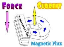
Sure, lots of folks look into it. One example is transverse flux machines.

Transverse Flux Current Flux Force.jpg

Materials can be figured out after geometry, IMO. Got an idea? Go for it.

major
 
Back
Top