Recumbent BikeE for Comfort and Efficiency

Great stuff Alan! Looks like your planning this out a whole lot better than I ever did. I just kinda looked at it a few times, got a rough idea of what was possible and went for it overcoming any issues as they arose. :lol:

When I built my pack, it wasn't until it was partially assembled that I realised I should be better insulating each series group from each other. I just used a few layers of electrical tape to keep things nice and thin. Seems to have worked....I am now at over 110 cycles on my pack since it was put in the bike.

I haven't measured, but from memory the Sanyo's are 18.2mm as are most of the current cells out there these days.

I will say this, I'm glad I went with 14S not 12S as I had considered. The nature of 18650's compared to LiPo is the voltage drops a lot more a lot sooner, so the net effect is the speed drops a noticeable 10kph as the battery discharges. I actually like this as it means that the efficiency goes up as the battery is depleted meaning it has less load and the last bit of charge lasts longer. The point is, if your expecting the voltage curve of 14S 18650's to be anything like LiPo you will be disappointed. This will be even more noticeable with only 4 cells in parallel as my experience of this is from drawing the same amount of current (~25A) from 5P.

Make sure you take some photo's/video of the battery building and installation process. I'm exited to finally see someone attempt this challenge!

Cheers
 
You did an amazing job of getting in there and getting it done. My projects take longer, but I do enjoy the design. This gearmotor doesn't need quite the current of your DD motor so I'm not trying to fit 5P in which should make it easier. 14S will be a nice speed bump over 12S, and more of my ebikes are 14S than anything else, so it is becoming a "standard" around here.

Thanks for the 18.2mm diameter data. I put 18.4 in the design but this latest printed part only has room for 17.45 so I'm going to have to adjust things for this new Slicer. The old slicer was closer to correct size but made some errors on the print. This new part does look better in many respects, now that it is using the right print settings. Looks like it forced two perimeters even though there isn't room for more than one. No wonder it is thick. I'll have to study the adjustments. This was printed without any changes to the new slicer default settings, need to start somewhere.

I will get some photos of the battery process, and I have a few other 18650 packs so I've seen the performance drop you are talking about. The big Lipo packs are amazing.

This is more of a feasibility study to see if there is an easy to build design, I don't have cells yet. Before making that investment I want to be sure it isn't a difficult fit. This may also help others to follow a similar path.

So I found the slicer setting for perimeters, it was at 2, it must have overridden the fact that there was only wall thickness for a single perimeter. Printing again. :)

I have a stack of trial 3D prints from the new slicer, but it is starting to look better and better. One of the values of the printer I have is a large set of pre-tuned filament configurations for it's free slicer, the new slicer came with few and some of the default values were wrong, like the filament diameter was slightly off and the hot end temperature was a bit low, and there were several settings that were preventing printing thin perimeters. I generally don't print such thin parts so I hadn't run into the issues with the standard slicer. It was making parts thin enough but there were other defects.
 
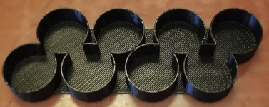
Test print #11 looks pretty good. The test cells fit, if anything they are a bit loose, so I probably went a bit too far on that. :)

I'll make a couple of small changes, but we're back on track for a useful part, using the new slicer (Simplify3D). It is hitting the dimensions pretty well, and looking solid, but not perfect. It is printing pretty fast, perhaps a little less speed would be good. I don't want to tune too much since the final part will probably be made with PETG instead of this PLA, so the final tuning should wait for that. I don't like to use PETG right now because it sticks to the PEI on glass bed so tightly that it is hard to remove, this PLA comes off nicely. But for the production part the PETG is much tougher. and will handle higher temperatures. PLA sitting in the sun can get soft around 60C which is not good for a battery insulator.
 

Attachments

  • batteryHolder11.PNG
    batteryHolder11.PNG
    154.3 KB · Views: 2,098
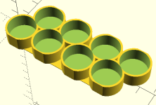
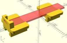
I redesigned the cell holder test part, adding the math that calculates the cell locations from the various space, diameter and wall thickness parameters, so I can more easily tune the fit without hand fitting. I've learned a lot about the slicer so I've made more adjustments there as well.
Here's the the new design's first iteration. The walls are thicker, but cut in critical spots, to make the part stronger but still meet the fit requirements. The diameter has been adjusted to 18.2mm and 0.4mm is allowed for space to the walls. We'll still have to adjust for fit as this print doesn't initially adjust for printing accuracy. Generally there is a little growth beyond the design's values that needs to be "tuned". This slicer (S3D) is hitting closer to the numbers, but I expect more tuning ahead, and again with PETG.

One issue I'm facing is the printer's nozzle is 0.5mm which makes it hard to go below 0.6mm width in printing since there is a slight growth. The layer height is 0.2mm so it is printing a 0.6mm wide and 0.2mm high bead as it goes along. If I had a smaller diameter printhead it could print thinner details. A common nozzle these days is 0.4mm, that would be a little better for this.

One thing about this design is the contact area with the sides of the frame tube is minimized, this should help reduce the friction sliding this into the frame. Perhaps some rails in the bottom corners can be in the final design to reduce friction there where it is greatest, underneath the pack.

Normally a 3D print design can be completed in a couple iterations, but this one is more critical than usual. We're not in a rush. The test prints like this one are taking about a half hour and using less than 17 cents worth of material. :)
 

Attachments

  • batteryHolderIIv00.PNG
    batteryHolderIIv00.PNG
    8.9 KB · Views: 2,080
If you've got any space, you should fill it with padding.
The biggest concern I still have with my pack is every time I hit a large bump or pot hole and I'm thinking about all those vibrations going straight into my battery. One of the few drawbacks of not having the suspension model of the BikeE.

I managed to squeeze semi thick padding along the bottom of my pack, but could not fit it along the sides or top. The 2 layers of thick PVC heat-shrink and some thin thermal padding is all the padding I have along the sides, as well as some hot glue along the top as a buffer for the wires.
I've now hit 114 cycles and not seen any issues though, so it's holding up well. My cells are amazingly in balance also, and I practically never need to balance them, even though I occasionally do.

When do you get your cells?

Cheers
 
I may have some room vertically, but horizontally there's just not much space. The printed plastic is pretty tough, but there's not room to really "pad" things. Good to hear your pack is doing so well.

I have not ordered cells yet. I want to have a good design before I make that investment. Getting cells seems to be a problem. I do have a welder and some nickel.
 
Today I drug the BikeE out of the garage for some measurements and test fitting. Between where this bike is stored and the weather it has been hard to get to it. It is also difficult to make good measurements so I've been using some very old values for the width inside the frame channel. This turns out to be critical to the battery holder design.

The good news is that the channel is wider than I've been calculating for. This makes a huge difference to the design and explains why Cowardlyduck's two row offset tightly pack battery could fit width-wise even with two thick layers of heatshrink on it. The best value I have measured so far is probably the 36.5mm based on the outside measurement minus twice the metal thickness. Before I was using 35.0, and gaining 1.5mm is HUGE when we are trying to fit two rows of 18.2mm cells.

This means I can give more space to the cell diameter and to the frame clearance and still use the 0.6mm minimum print width, so I should not have to change to a smaller printing nozzle. It also means the potential for a successful 3D printed battery holder is high.

Most of the vibration acceleration is vertical, since bikes lean, so perhaps I will put some padding under the cell holders where it would do the most good. I haven't looked at vertical space too closely, I don't think there is a lot of room there, but it is not as tight as the horizontal fit. Just to put a number on it, 89.7-2*2.38=84.94 which is quite close to the 85 value I've been using...

I also took new outside measurements so I can go forward on making an adapter of some sort to mount a Shark pack on the tube without making holes in the frame tube. This will allow me to go to 52V with my existing Shark pack before I get a frame pack built, and it will give me a range doubler when the in-frame pack is in place. The BikeE frame is basically a rectangle, but at the top there are ears sticking out about 6.3mm wide and 7.8mm high. These are used by the seat clamps to keep the seat on the frame. They might also be useful keeping a Shark battery on top of the frame. The Shark is 370mm long and the space from my seat position to where the chain crosses the frame is 460mm, so there's quite a bit of space to put the Shark there.

Outside Frame Measurements
width outside 41.3 bottom (rectangular section), 53.9 top (crimp)
height of crimp 7.8 (so rectangular below this point)
total beam height 89.8
metal thickness 2.38
in mm
 
Looking great Alan. Initially I made the hot glue buffer on the top of my pack too tall and it would not fit nicely, then I re-melted it and flattened it down in order to make it fit with room to spare. In the end I managed to keep all my electrical wiring inside the frame still sitting on top of the pack and only had to route the brake and gear cables external.
Do you plan on running all wires external or keeping some internal?

That frame clamp is a great idea, and the sort of thing that has been on my mind for a while, but I'm yet to dive into the 3D printer scene otherwise I probably would have tried making one already.
I might be interested in buying a few off you once you've perfected the design as I can see it being useful for my magnetically attached rear bag. It still comes on the odd occasion when hitting a huge bump or pothole.

Do you plan on paralleling your external pack with the internal pack, or will you just drain one, then the other?

Cheers
 
I like what you did with the cables under the frame, though it would be great to keep them all inside. There probably won't be enough room in the frame with the internal battery. We'll have to see when we get closer to a final design how much room there is. Nothing wrong with a nice bundle below the main beam.

I generally charge my booster packs and main packs to the same voltage and then parallel them. Someday I'll make a smart switch to parallel them dynamically, then separate them when the bike's not drawing power.

I'm considering alternative designs for the frame clamp to grab the frame without scratching it. Mounting the Shark could go quickly if I come up with the clamps. I could also put the PhaseRunner on, that would be fun to test. Need to set up the trunk mount, so the frame clamps come in handy again. The internal pack will be a bit later. Good riding weather is coming soon...

I might do a chain guide, that could help keep the chain on, I had it derail once in the front.

The 3D printer is the best tool I have bought in years. A useable one is not that expensive, though there are some cheap ones that turn into more of a project than a tool. I'd like to get another one, the new Prusa I3 MK3 is really looking good on the high end, and the kit version is quite a savings over the build model. If I was going to get something inexpensive I'd probably get a Monoprice Select Mini.
 
I was able to keep some wires in the frame by keeping all the battery wires centred along the top. That way, my existing wires could go either side on top of the battery. In my case the humped battery top with smooth PVC heat-shrink and lube made it relatively easy to slide the battery in with the wires pulled tight which guided them into place. I do not think it would be easy or even possible to feed the wires in after the battery has already been inserted.

Thanks for the 3D printer suggestions. I really have no idea what's best and am still torn between forking out for a high end unit first time round so I don't have to worry about it down the track or just getting something cheaper first off till I see how much I actually need/use it, then getting a second high end unit later.

One of the 3D printing idea's I've had is to make some sort of mount for my tools bag just under the frame in front of the rear forks. I currently have mine sitting at the very rear of the tail hanging off some zip ties and velcro which means it's always swinging about a bit. I would put it under the seat, but I've managed to cram 2 tubes (one for each wheel size) in there with a whole lot of pushing. An angled 3D printed piece that clips into the hole just in front of the rear forks would be perfect for housing all my tools as well as my charging plugs and balance leads.

I think because the frame of the BikeE is so simple, it can make mounting things a bit of a challenge as there are not many angled nooks like a normally framed bike where you can stash things.

Cheers
 
Choosing a first 3D printer is not easy. The last couple of years has been a race to mediocrity and low pricing, the market is flooded with cheap printers by now that can really sour a new user by having poor or inconsistent results. Prusa sort of invented low cost 3D printing for the masses, really adapted it to low cost, and he's still pushing the envelope. Anything they make is probably good. His new I3 MK3 is not cheap, but it pushes the envelope in a number of ways that no other printer presently has. The Monoprice Select Mini gets a lot of decent reviews, it is an example of cheap and cheerful that works. I have a Lulzbot which is a good printer, but it is too expensive and has one annoying flaw that I'm fighting a lot, it has an auto-levelling system that doesn't always work. WHen it works it is great, when it doesn't it is a problem.

The Prusa has a different approach to auto levelling that is better.

In any case there are lots of 3D printer reviews on utube to look at, don't buy before doing thorough research.

If you can do some 3D CAD the printer will make things that in some cases you could not make otherwise, and it is cheap and fast. Custom mounts and brackets are a good application for 3D printing.

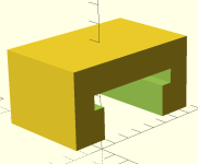
I printed out a small test to check my cross section for the exterior frame mount bracket. A few iterations should be able to tune that to precisely fit on the frame and top rails. From that many different types of brackets can be developed. I have some ideas to make it swell on the inside to grab the frame so it won't slide. First goal is the Shark battery mount.
 
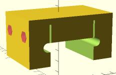
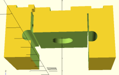
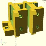
Working on the battery mount design. Added cross bolts to clamp the mount to the frame without damage. Hex holes accomodate a female hex standoff to take M5 screws from both sides to provide clamping tension. Slits focus the pinching on the frame. This leaves the center clear for bolting the battery to. Frame clearance changed to semicircles for a better fit. Have yet to recess the cross bolts.

The downside of this approach is a bit more vertical height above the frame needed.
 

Attachments

  • frameClamp.PNG
    frameClamp.PNG
    2.5 KB · Views: 2,001
Here's a front and rear mount for the Shark battery. To make the battery more secure I plan to use one rear and two front mounts. The rear mount is designed to bolt to the metal plate of the Shark mount. A hole will be needed in the plate as this is not a usual mount point for a Shark. Then two front mounts can be used, one near the center and one near the front.

These are going to be a little difficult to print, with all the features and internal holes. Some of the holes may require cleanup. I plan to print with the frame slot pointing up.

Fine tuning has not been done on the fit dimensions yet, that will require some trial prints, not of the whole block but of a slice.

This will likely be stronger than the mounting tabs of the Shark battery itself, so in a crash the failure point will most likely be those ears. Velcro straps around the battery and mount might help, or avoid crashing.
 

Attachments

  • frameClamp3.PNG
    frameClamp3.PNG
    9 KB · Views: 1,993
Made the first full-up print of the forward mount (with the slot). The print came out better than expected, especially with regard to internal holes. The hex holes were printed quite clean even with difficult overhangs and no support. The small round holes are not bad either. So far found one flaw - while it was printing I realized that we need another pair of slots to clear the locking tabs on the battery. The full print will be used to check many dimensions and make mostly minor adjustments, with a little luck print #2 will be useable.
 
The hex threaded standoffs were a nice idea, but they take a lot of space and the printed hole for them came in quite a bit undersized. They are also somewhat expensive. So I've changed to 70mm M5 capscrews with a washer into a T nut. The simplest way to use a T nut here is to flatten the prongs and epoxy it into the other side. Or heat it and melt it into the plastic with a large soldering iron.

This will allow the part to be made a little smaller, and remove the need to hit the hole dimensions as precisely. Also it is easy to clean out a round hole with a drill bit, not so easy to clean out a hex hole.
 
Had a chance to sneak out and check the fit of the first full print on the BikeE frame a few minutes ago.

The good news is, the fit is amazing. I will increase the clearance a bit but it fits nearly exactly. Just a little more friction than I want without any tension on it.

The not so good news comes from not looking carefully enough at the bigger picture. Now I have a nearly exact fitting mount, but there's no easy way to get it onto the front frame section. The rear fork mount is in the way. It will work great for a rear rack mount. But the rear fork mount goes very high on the frame. So I'll have to shorten the mount a lot to fit over the top of the fork. Not hard to do, perhaps not a problem at all. But not what I was planning.

I could also make the mount come apart. Then it could drop on anyhere, and still be the size it is designed now. I'll have to look into that. But the one piece block will be great for the rack.

I could also remove the rear forks to slide the battery mounts on. This is something I plan to do later anyway. It would just require fabricating a replacement attachment system for the rear forks, which I already have a plan for. But it is not something I was expecting to do until the internal battery project made it necessary.

Additional note - making the mounts separate looks good. More soon...
 
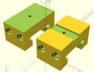
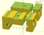
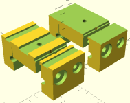
It is nice to be able to easily slice a design into two parts in such a way that they interlock when in use. Here's a first try at that. The two components have been slightly misaligned along the frame axis so we can see clearly where the break is. The overhang locks the central part in so that any lifting force will be transferred to the frame ears on both sides and the whole mount will remain locked in place.

To do this precisely in OpenSCAD I made a cutter with two cube shapes, and the part is intersected with this shape for one side, and subtracted to get the other. This way only one "cutter" is used, and only the math operation is different, so the two parts are precisely complementary.
 

Attachments

  • frameClamp4.PNG
    frameClamp4.PNG
    4.3 KB · Views: 1,946
I know you've already put some effort into this, so sorry I didn't think to mention this till now, but would it make things any easier if you just bought some of these seat sliders and made the 3d printed part to sit between them and have a QR skewer holding it all together:
https://store.bicycleman.com/products/bike-e-seat-sliders-pair
CRW_6091_edit_3d4526ac-9a53-44d3-8364-10ae3ea0fa78_grande.jpg


This is kind of what I did to hold my rear bag in place.
DSC_4181.jpg

DSC_4183.jpg

This solution is still working well on a daily basis.

Anyway, just an idea that might make this undertaking a whole lot easier.

Cheers
 
Thanks for the tip. I've had a web page open on those for some time, I need to order some to upgrade my seat. That's not a bad solution and I have considered it for this battery mount. It would be easier, and would not require fancy 3D printed parts. A block of plastic with a couple of holes drilled would do the job.

If I didn't have a 3D printer I'd go that way. They are a bit pricey, but nicely made.

Given that I have the printer I think these more complicated 3D parts may be a bit better for the battery and trunk mounts. For the seat mount the extra strength of machined Delrin is worthwhile.

I should order a set and see how they work for the seat. I have the original round seat mounts and they seem to work ok, but with the motor I don't have to pedal hard which really stresses them.

Thanks!
 
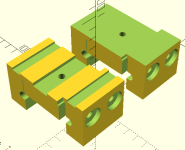
Updated the design with more accurate tee nut holes, cleaned up the code. Front and rear mounts, slightly offset to show separate pieces. 70mm M5 cross screws and tee nuts. M5 mounting hole with tee nut below. Need to order hardware, this is looking good.

Ordered hardware, some of which is not going to arrive very quickly. 70mm M5 capscrews seem to take awhile. Found some M5 tee nuts at the hardware store, but not the long capscrews.
 

Attachments

  • frameClamp5.PNG
    frameClamp5.PNG
    9.1 KB · Views: 1,924
I made a few more changes, adding a centering tab to keep the two sides aligned, and tuned the tee nut holes and counterbores for diameters and a washer on one side with the tee nut on the other, one pointed each direction for symmetry.

Started looking at 14S BMS boards. Might be interesting to experiment with one on the internal battery. Anyone have any good suggestions? 30A rated, small enough to fit in the frame where the rear forks are?
 

Attachments

  • bikeeFrameClamp6b.PNG
    bikeeFrameClamp6b.PNG
    7.8 KB · Views: 1,908
  • frameClamp6.PNG
    frameClamp6.PNG
    8.9 KB · Views: 1,905
Combined two of my designs together and came up with this Trunk Mount that clamps onto the rear tail of the BikeE. I've used this mount on a RadCity and it works very well. I'm not quite done with this design, there's always a couple more changes to make in this case to make it more printable, and to use more available hardware for the clamping screws.

If you are not familiar with the Topeak MTX trunk, it has a dovetail that slides into the track, and a latch that slides into the slot at the end and locks into place. Very convenient and the one trunk can snap onto the various bikes quickly and efficiently.


TopeakMTXbikee.JPG
 
This version was tested and fits on my bike and trunk.

You can see the RadCity bike rack version of this MTX compatible adapter on my son's bike in that thread. That has worked out well though I had to adjust it for a slight offset in one of the holes. Hopefully the Bikee extrusions are really consistent so we won't have a fit problem like that.

This design uses M5x70 capscrews, washers and tee nuts. The tee nut prongs need to be either melted into the plastic or flattened and epoxied into place.

Here they are in print orientation:


BikeeMTX.JPG


Here's the STL file that can be used to print your own. It is my own original from scratch design. Who knows if it will fit any particular BikeE or ToPeak rack other than mine. It is not for commercial use. Anyone making this should give me feedback on how it works out.


View attachment topeakBikee.7z
 
Back
Top