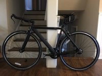
Single-speed track stealth ultralight

eCue said:
Your bike has turned out really nice that hub looks no bigger then a IGH IMO. Comparatively my 350w Mxus xfo7 looks beastly :D

Thanks eCue! This motor really is teeny, even the Q100 looks large next to it. The real test though is how it rides, and I can't wait to find out. I'm hoping that my throttle parts show up today.
 
cwah said:
Where did you buy the torque arm?

The trouble I had was that most torque arms are designed to work with dropouts, and my bike has track forks, not dropouts, so the angle would have been weird or possibly unworkable. What I ended up getting is the Amped bike style torque arm from Luna since the arm and bit that goes on the axle can be positioned independently.

Aaaaaand, I just realized that that torque arm is designed for 14mm axles, and my motor has only 12mm axles (facepalm).
Well, maybe I'll be able to make it work. My frame has stainless steel inserts on the axle slots anyway, so maybe it won't be a huge deal at 600W.
 
zro-1 said:
Aaaaaand, I just realized that that torque arm is designed for 14mm axles, and my motor has only 12mm axles (facepalm).
The flats are still 10mm, so as long as the torque arms are a precise fit on the flats, it's less of an issue than you might expect. If there is space for the axle to rock back and forth between the flats, then you'd probably have to shim it between the axle flats and the flat part of the arm to ensure it is secure.

The biggest problem with that particular style of torque arm is you need to ensure the arm itself is in good planar alignment with the star part that fits on the axle. If it is not, and there is any way for it to shift off the star's edge, there's nothing holding the star anymore from rotating, so it's not a torque arm anymore at that point.

Washers that are as large in diameter as the outer part of the arm around the star insert hole will prevent that, on either side of it in the stack of hardware on the axle.
 
amberwolf said:
zro-1 said:
Aaaaaand, I just realized that that torque arm is designed for 14mm axles, and my motor has only 12mm axles (facepalm).
The flats are still 10mm, so as long as the torque arms are a precise fit on the flats, it's less of an issue than you might expect. If there is space for the axle to rock back and forth between the flats, then you'd probably have to shim it between the axle flats and the flat part of the arm to ensure it is secure.

The biggest problem with that particular style of torque arm is you need to ensure the arm itself is in good planar alignment with the star part that fits on the axle. If it is not, and there is any way for it to shift off the star's edge, there's nothing holding the star anymore from rotating, so it's not a torque arm anymore at that point.

Washers that are as large in diameter as the outer part of the arm around the star insert hole will prevent that, on either side of it in the stack of hardware on the axle.

Whew! That's good to know! Thanks amberwolf.

I'm investigating an option for a 0.25mm shim to insert on the axle flats to get rid of the slop that's in there right now.
 
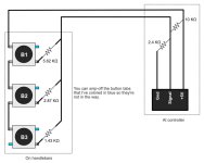
I'm adding a refined diagram of the 3-button throttle (I've edited the original post mentioning this). I'm adding it because I found it challenging to correctly solder the tabs on the buttons so that the throttle worked as I designed it. Hopefully the new diagram helps others who want to make the same throttle.

3-button_throttle_wiring_v2.jpg
 
zro-1 said:
I'm investigating an option for a 0.25mm shim to insert on the axle flats to get rid of the slop that's in there right now.
That seems like a lot of slop. :(

Automotive places probably carry shims for various things.

If you get desperate they might have a spark plug gap checker that's got individual slide-out tabs (rather than the round keyfob types) that you could cut the right-thickness tab off of to use. They're usually steel, at least.
 
haha! The spark plug gap checker is exactly what I was thinking of.

I scraped together a test 3-button throttle to see how it reads in the Phaserunner. Here's the results:

No buttons pressed: 0.91V
Button1 pressed: 1.67V (was aiming for 2V)
Button1 + Button2: 2.5V (was aiming for 3V)
Button1 + Button2 + Button3: 3.23V (was aiming for 3.8V)

I'm not sure why the voltage is lower. Maybe its from the buttons since I didn't take them into consideration when I was doing my parallel resistor calculations. I had read the voltage coming out of the Phaserunner back when I was troubleshooting the halls in the Q100, so I know that it's putting out 5.3 volts between the positive and negative pins. The resistors I ordered were "1%" rated (not sure what that means), but I'm guessing that it means they are within 1% of their rated resistance. I wonder if that 1% is enough to change the voltage readings that much.

Screen Shot 1.jpgScreen Shot 2.jpg

For me, it's not a huge deal because the Phaserunner has a programmable throttle setting, so I can lower the full throttle voltage. For others that may want to use this on a controller that can't be programmed, this would result in only partial throttle.

If any of you have an idea why the voltage might be lower than my targets, I'd love to hear your thoughts.
 
So since I couldn't do any more work on my bike, I figured I'd shift gears and do some work on my 2nd attempt at a seat bag battery. If you go back to page 3 of this thread, You'll see that I made an idiot mistake and welded series strips in the middle of my parallel strips. This was a huge mistake, and I was really lucky that I didn't cause a short that would have resulted in fire. I'm not even going to show the pic of that since it was such a stupid mistake.

I had pulled that pack apart, and when I did, I realized I'd melted the insulation on the battery cells in several places. There was a smidgen of plastic left there, but it was only luck that the nickel strips were stiff enough that they didn't flex down and onto the exposed negative pole shells. I scavenged the cells that were undamaged and bought a few more to make my current pack that lives in my backpack (which is working great by the way).

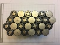
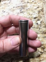
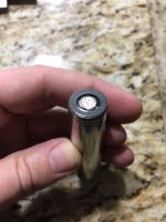
With the cells that were left, I filed smooth the ends, and tested them through a few cycles by using them in turns in my vaporizer (2-cell, 70W eCig) and confirmed that they were ok. So I ordered a few more cells, and I got to replacing the pads and shrink-wrap on all of the cells. For coolness alone, I decided to get black pads and clear shrink-wrap. I ordered the bits from IMR batteries, and the quality was very good. The pads are paper (won't melt) and nice and thick (like poster-board or card-stock at the minimum) and the shrink-wrap ended up being slightly thicker than the stock LG stuff. Since they looked so nice and the pads were thicker than the stock stuff, I decided to do the new cells too.

Here's a couple of pics of the freshly padded and shrink-wrapped cells, just for ooo's and ahhh's:
cleaned-cells-1.jpg
cleaned-cells-2.jpg
cleaned-cells-3.jpg

I don't think I ever mentioned it, but I'm using LG MJ1 3500 mAh cells. If you're curious, you can see what they look like in the factory shrink-wrap in one of my earlier posts here.

The pads and shrink-wrap I got from IMR Batteries was top-notch. The pads are self-adhesive stickers, which makes positioning them very easy and they're twice as thick as the factory pads. The shrink-wrap was precut to the perfect length. It fully covers the pads with no slop when you center the cell in the shrink-wrap. It's even better than the factory stuff in my opinion.

Oh, I should note that I filed down the welds while the old wrap was still on there being careful to avoid the bare spots, and after filing off the weld marks, I blew off the cells with compressed air after removing the factory shrink-wrap. I also cleaned all the surfaces with alcohol wipes.

I like the look of these shiny metal cells so much that I may wrap the battery in clear packing tape. They'll be in a bag, so no one will see them but me, but its one of those things that will make me smile whenever I take the battery out of the bag.
 
cwah said:
By the way, it looks like you install on the rear? There isn't a cassette version I suppose?

Sorry cwah, I'm not 100% certain of what you're asking. By "install on the rear" do you mean my track forks on the bike? If so, yes I have track forks back there. The motor normally comes with 135mm axle width for 6-7 speed freewheels (no cassette version). Th axle is 12mm with 9.75mm flats. The slightly small flats may be a mistake since I special-ordered my motor with a 120mm width axle, but if your dropouts can accept a 10mm axle this will work. If they're small, then the fact that this may be cut to 9.75mm means less filing to make it fit. (I can't be certain of what the stock motor's flats are like since I only have one and it was custom-built)
 
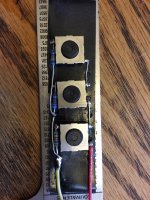
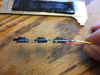
I finally got the buttons I needed to complete the main part of the throttle. I'm still waiting on the heat shrink I ordered from HK to show up so I can wrap the wires going back to the controller. Still, I can at least finish the build part and get the bike tested properly while I wait on the wrap to finish it completely.

Here's pics of the buttons after I got them soldered up, and before I pot them with liquid tape.
button-v2-1.jpg
button-v2-2.jpg
 
Do any of you know of a good free open source or web-based PCB design software? I'm currently potting my 3-button throttle to a pice of plastic, but I feel like I could make something much more precise and reproducible by using a printed circuit board and surface mount resistors along with the surface-mount buttons I already have.

I'd be happy to offer the resulting schematic and parts for free here so that any of you can make one for yourselves too.
 
There's been a few threads about PCB stuff, if any of these help:
https://endless-sphere.com/forums/search.php?keywords=PCB+software&terms=all&author=&sc=1&sf=titleonly&sr=topics&sk=t&sd=d&st=0&ch=300&t=0&submit=Search

https://endless-sphere.com/forums/search.php?keywords=PCB+design&terms=all&author=&sc=1&sf=titleonly&sr=topics&sk=t&sd=d&st=0&ch=300&t=0&submit=Search

I haen't used any in years now, so cant' remember names.
 
Sweet! I'll look through those. Thanks amberwolf

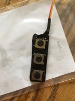
One last pic of the 3-button throttle. I've got it all potted to a piece of plastic. The buttons themselves are IP67 water-resistant rated, but I wanted to seal all the other bits. Plus the potting helps provide support and structure to the whole thing since it'll be on my bars getting mashed by my fingers a bunch every day.

button-v2-3.jpg
 
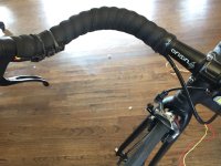
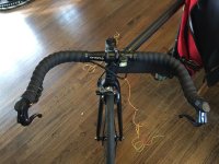
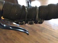
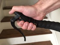
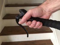
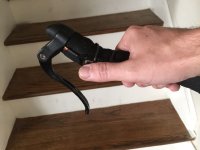
So now that I finished making the button throttle, I got it on my bars and was able to finish wrapping them. I also decided to tape the throttle wires cleanly to the rear brake cable so that they disappear and I don't have a separate wire zip-tied to the frame or cable. I have the buttons secured with a couple rubber bands for now so that I can play with the positioning till I get it right were I like it. The button throttle can be activated at all 3 levels from two hand positions, and I can use level 1 (30% throttle) in a third position with my thumb. I haven't gotten the bike out on the street yet though, because I still need to complete the wiring down to the controller and fine-tune the throttle input setting in the Phaserunner.

Here's the pics:
handlebars-1.jpg
handlebars-3.jpg
handlebars-4.jpg
handlebars-5.jpg
handlebars-6.jpg
handlebars-7.jpg

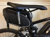
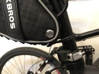
I'm also making quick progress on the seat-bag battery. I found a nice waterproof bag that looks to be just the right size to squeeze in the 13s2p pack and BMS.

seatbag-1.jpg
seatbag-2.jpg
 
That bike looks fantastic. Great work. I think you really have completed your brief with this build. No one will pick this for electric assist.

You button throttle arrangement will work fine however I think after a bit of riding you will wish the buttons latched rather then needing to hold them on when assist is needed. Not sure if you have followed my latest Arduino button arrangement, https://endless-sphere.com/forums/v...0f61672bf1da89284722f6982d&start=325#p1368222

I am just finishing off a new setup using an Arduino, buttons, and a microswitch on the brake lever.

Operation is as follows:
press button 1 => fast ramp to 50% throttle and latch
press button 2 => fast ramp to 100% throttle and latch
You can toggle between the 2 buttons any time and latch each speed as required.

Press button 3 (microswitch on the brake lever) throttle is killed. However there is a 4 second ramp back to zero % so the motor deactivates smoothly.

So this setup is programmed to drive a PWM signal however you could just as easily drive a variable voltage output.

A project for the future perhaps.
 
Thanks so much Kepler! I had not seen your Arduino button throttle thread, but I am definitely going to be checking it out now. I'm a constant tinkerer, so I'm sure I'll be tweaking things on this bike as I go (as I've already been doing with it). I like the idea of using a programmable Arduino to control output more precisely than resistors which have a margin of error. I spent a lot of time fiddling with resistor values in the calculator I used, but they still aren't perfect. If I hadn't been able to program the Phaserunner to accept different values, I'd have had to go back to the drawing board.

At first thought, I'm not sure if the latching throttle would work for me with the way I ride and environment I ride in. I'm constantly fiddling with the throttle level and almost never leave it at one setting for very long. Also the phaserunner offers ramping on start/stop so I can tweak those setting to make the motor smoother. Then again, I haven't gotten the bike out for a ride yet, and I may end up wanting a latching throttle on this smaller motor. We will see.
 
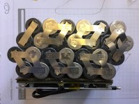
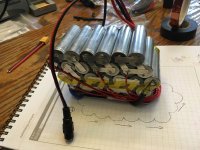
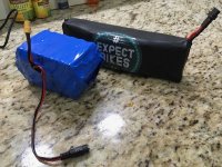
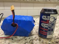
I got the seat bag battery all welded up and BMS connected. It juuuuuust squeezes into the seat bag with a little room to spare for tucking in the charging cable and an on/off switch to the Phaserunner.

bag-battery-1.jpg
bag-battery-2.jpg
bag-battery-3.jpg
bag-battery-4.jpg
bag-battery-5.jpg

One really great thing about this setup is that if I have a longer trip I can toss my backpack battery in the backpack, then hook it up when the seat-bag battery runs low. Both batteries are 13s2p 7Ah packs.
 
Nice work on the new seat bag battery! Interested to see how you like it on the road. Also like the 3 button throttle idea and your approach to engineering this. Your process of developing and improving this setup is really impressive, I see a minimal road bike kit in the making, you have your first buyer here :D
 
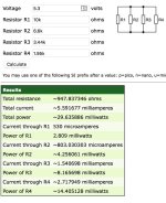
I figured out why my throttle voltage is low. I calculated my throttle source voltage at 5V when it's actually 5.3V coming out of the Phaserunner. That changes the values of the resistors pretty significantly.

This is what the correct resistors should be for the Phaserunner when using a 30/60/100 3-button throttle.
resistors.jpg
--

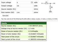
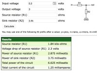
You will typically be using a 10KΩ source resistor and a 2.4KΩ sink resistor to make the "zero throttle" default input signal. But you'll want to measure your voltage coming from the controller first to make sure you have it right. Once you calculate the correct "zero-throttle" resistors for the voltage divider part of your throttle, these two resistors will never change with the rest of your calculations. You can use this voltage divider resistance calculator to determine what your source and sink resistor values should be so that you have about 0.9V to 0.93V when no buttons are being pressed.

So my advice to any of you who want to build this throttle is, measure the source voltage of the throttle connection off your controller first.

Then what you do is use this voltage divider resistance calculator to determine what your total resistance will be needed for your given target voltage. You will be using this value as a reference as you enter multiple values into the parallel resistor calculator next.

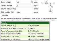
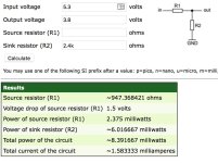
So you enter the voltage you got off your controller, then you set 2.4KΩ as the sink resistor, or whatever you ended up with from your initial calculations (that will never change). Then you enter your target voltage. I estimated 2V to be about 30% throttle, 3V to be about 60% throttle, and 3.8V to be full throttle. As you change the output voltage, you will be looking at the values shown in the green box for the source resistor (R1) value.
resistor-30-percent.jpg
resistor-60-percent.jpg
resistor-100-percent.jpg
--

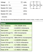
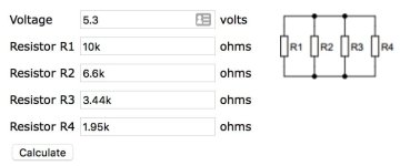
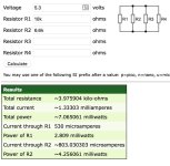
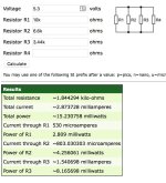
You need to keep in mind that you will have a 10KΩ resistor as R1 in the parallel calculation, so you'll enter this first as the R1 value in this parallel resistance calculator. You will enter the same exact source voltage you measured off your controller here as you did for the first part with the voltage divider. You'll then enter R2, R3, and R4 values one at a time until you get the correct total resistance that matches the source resistor values you calculated before.

30% parallel values:
resistor-30-parallel.jpg

60% parallel values:
resistor-60-parallel.jpg

100% parallel values:
resistor-100-parallel.jpg
--

I have enough spare buttons to make 2 more throttles and I'll order more resistors of the correct values to make a new 3-button throttle some time in the future. I am very lucky in that I can program the Phaseruner to use a lower throttle setting for full power, so I don't need to change the buttons out right away.

What I want to stress to you guys reading this is that you need to measure the actual voltage coming off of your controller in order to know what resistors you need for your three buttons. Otherwise you could end up with over or under voltage scenarios if you can't program your controller like you can with the Phaserunner.
 
zro-1 said:
So my advice to any of you who want to build this throttle is, measure the source voltage of the throttle connection off your controller first.
Or use a tiny potentiometer, and adjust it for the zero voltage once it's hooked up to the controller. There are some micro pots that are *almost* as small as a 1/4 watt thru-hole resistor; about the same size as a pair side by side. Not sure how easy to handle/solder they are, though.

Would be sealed into position once the whole module is "potted".

The same could be done for the other resistors, but I'd venture it's less critical that those be precise values to get approximately the right percentages of throttle output.


What I want to stress to you guys reading this is that you need to measure the actual voltage coming off of your controller in order to know what resistors you need for your three buttons. Otherwise you could end up with over or under voltage scenarios if you can't program your controller like you can with the Phaserunner.

If it's an overvoltage (so there's no zero throttle), and the controller has no adjustments, then that can also be fixed with a potentiometer, on the output of the throttle switch assembly. Main two contacts go from output of assembly to ground, and wiper goes to signal input to the controller. Might have to be a pretty high resistance so it doesn't alter the parallel resistances of the switch assembly and just acts as a voltage divider.
 
I added a remote button for the Phaserunner to the tip of the seat bag where there's a void in front of (or is it behind) the battery.

remote-switch .jpg
--

The bag's sidewall is made of thick waterproof material with a layer of foam sandwiched between it and the inner lining of the bag. So what I did was snip out a hole that was a bit smaller than the button, then I brushed the edge with some liquid tape, and jammed the button in until the rubber o-ring on the switch was contacting the bag. I then tightened the lock nut on the backside of the button up against the material. The bag is stiff enough that it doesn't flex too much when you press the button in to turn the controller on. The button is also flush when off (and recessed when on) so you can't accidentally turn the system on. You have to be deliberate when turning the unit on or off.
 
I finally got the bike out for it's maiden test ride in it's new form. I took it around my neighborhood up and down some small hills to get a feel for it.

The bullhorn bars are definitely going to take some getting used to. With the shorter stem, the steering is a bit more twitchy than when I had the wide riser bars and longer stem on there. The SRAM Red calipers in conjunction with machined sidewall rims are amazing. In the dry, they feel every bit as strong and modulated as mechanical disk brakes. Now for the electric bits...

The 3-button throttle

It works fantastically! Once I got the Phaserunner programmed for the current voltage levels returned by the buttons it worked really well. Using the dashboard in the Phaserunner software, to monitor throttle input I get a solid 30%, 75%, and 100% throttle. On the initial 2-mile run I did today I'd say these three levels are all I'll ever need.

The seat-bag battery
The seat-bag battery is great! It's nice not having to wear a battery on my back and have a cable dangling down to the seat. I think I was premature about dismissing the seat-bag idea the first time. I wasn't used to the feel of the different style bicycle and I wrote-off the seat-bag before I gave it a chance. Now that I'm used to the bike and have the seat-bag back on there it's not bad at all. I really didn't notice it—though I was also focusing more on the new handlebars, brakes, and motor. But I think it will be fine, and it's very convenient, especially with the on/off button right there.

The motor

Good bits first:
The motor performs really nicely! The motor's power and top speed at 48V is exactly what I wanted. It pulls enough that I don't have to work very hard up the hills, though I do have to work (which is what I wanted—assist, not pedal-less climbing). The top speed is good. I don't have a speedo, so I can't tell you exactly how fast, but Strava reports my top speed at 28.2 mph. I'm positive the bike can go a bit faster, but the twitchy steering had me a little nervous so I was taking it easy. At top speed I was still able to contribute pedal input without just ghost pedaling, which was one of my biggest complaints with the fast Q100.

The bad bits:
There's only two, the motor is noisy—even with the FOC Phaserunner. I don't even want to imagine what this thing sounds like with a square-wave controller. My BBSHD is the quietest, and on the Phaserunner I would say that the Q100 was only slightly louder. The YTW-06 is definitely a bit louder than both. It's not dramatically louder in terms of decibels, but the tone of the sound is more like an electric motor sound rather than the deeper hum of the Q100. My other dislike is the clutch; it's noisy too. I didn't feel any drag when coasting with no throttle or pedaling, but I could hear the clutch. It is just about drowned out by my loud White Ind. freewheel, but if I'm pedaling with no motor, it almost sounds like my brakes are rubbing or something (they're not, I checked twice).

I have read that both of these things get better as the motor breaks in and things seat with each other better. I will be sure to update either here or in the motor thread if and when that happens.

In conclusion

With only the one 2-mile test ride, I can't make any proclamations about the motor yet. The weather this week is going to be awesome here in Atlanta, so I'm going to be getting 50-60 miles on it at least. So I will post again next week with my real ride impressions of the motor.

My first impression is that the smaller size and lighter weight make this a very nice mini hub motor. It is definitely without a doubt worth the $75 + shipping. If you're already running a Q100, I'm not yet certain it's worth swapping out just for the size weight differences. if you don't yet own a Q100 or the one you have has died, this motor should be at the top of your list when looking for a replacement/alternative. The motor seems to pull just about as hard as the high-speed Q100 did—which is pretty crazy for such a little motor. I think I can tweak settings in the Phaserunner to get this running even better. I was a bit conservative on my initial settings, and I didn't go near any of the advanced settings other than adjusting the throttle input levels.
 
Back
Top