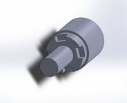
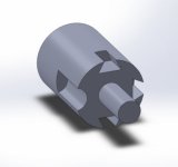
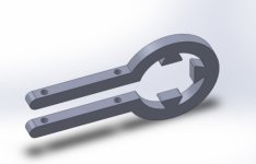
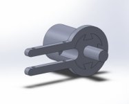
2018 Torque Arm Tests, Splined Interface Design and Tabbed Washers

e-beach said:
...
And if 4 points of orientation aren't enough, then a pentagon, hexagon, heptagon or octagon could be used.

:D

Hmmm... where have we seen this? :D

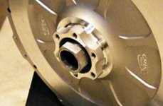
An early incarnation of the Grin Thru Axle hubmotor:


grinMotorHexTorqueArmAttachment.jpg
justin_le said:
And the hexagonal shape on the end of the axle is for an integrated torque arm. So there will be no spinout forces present on the fork dropouts.

This is clearly a product-specific implementation, but the idea has been visited before.
 
Chalo said:
If there's an adequate torque arm, it seems to me that you don't need orientation control. A regular round 10mm axle stud or bolt will do to fix the hub to the frame.......

Something like this? However on the flip side of the question will a bicycle frame hold up to 200nm of leverage?


LikeThisAxleAgain.JPG

:D
 
e-beach said:
Chalo said:
If there's an adequate torque arm, it seems to me that you don't need orientation control. A regular round 10mm axle stud or bolt will do to fix the hub to the frame.......

Something like this? However on the flip side of the question will a bicycle frame hold up to 200nm of leverage?

LikeThisAxleAgain.JPG

Yes, that axle would work fine-- and it could be drilled and tapped with female threads for a fine thread bolt or stud, to easily allow a harder material there.

How much reaction torque the bike's frame can take is partly a function of how long the torque arm is. Coaster brakes apply a lot of torque through a fairly short lever, but we can make one as long as we like.

200Nm of motor torque seems deep into the range of "not suitable for bicycle components". But if it were anchored near the bottom bracket end of the chainstay, it would only exert about 100 lbs of force there.
 
Alan B said:
A 100 kg rider standing on a 170mm crank arm pedal produces about 160 Nm of torque on the rear wheel with 1:1 gearing which is common in mountain bike drivetrains, unless my arithmetic is broken. Why would 200 be out of bicycle range?

Because it isn't applied at the dropout. The torque gets resolved as chain tension, which is much easier for a truss frame to manage.
 
Chalo said:
If there's an adequate torque arm, it seems to me that you don't need orientation control. A regular round 10mm axle stud or bolt will do to fix the hub to the frame.

EXACTLY. Part of the point here is to have a round axle that is perfectly free to rotate inside the dropout slot, and then you don't require several degrees of freedom on the remaining torque arm pieces to fit and align with the frame tubing. The actual orientation of the torque arm is not being defined by the dropout slot orientation.

I really like the loosely fitted hexagonal interface torque arm used on the Copenhagen Wheel, and I think more manufacturers should do it that way.

I had a hexagonal interface all of my earlier prototype All-Axle hub motor axles,
Hex All Axler.png

The thinking was that you could then use an off the shelf 25mm wrench as a torque arm in a pinch. But for a system that does regen even a little back and forth play can be a big issue for impact wear. I'm surprised that the torque arm on the copenhagen wheel is described as "loosely fitted". By that do you mean it's loose on the axle with a hex interface, or more that the way it secures to the bike frame (just with a single hoseclamp) is somewhat loosely defined? I'm curious to see exactly what theirs looks like, and also another case in point to my initial opening rant that as a general rule western designed hub motors generally have integral torque arm design, while only the china import motors keep using axle flats.

Alan B said:
A 100 kg rider standing on a 170mm crank arm pedal produces about 160 Nm of torque on the rear wheel with 1:1 gearing which is common in mountain bike drivetrains, unless my arithmetic is broken. Why would 200 be out of bicycle range?

I guess even more to the point here is the braking torque put on the frame from disk calipers when you are stopping. The calipers are located in a similar distance down the seatstays as a torque arm attachment and are dealing with torques even larger than what any motor can produce.

It's rare for hub motors to be producing more than 50-60 Nm, but for a torque arm a design target of 200 Nm seems prudent for good safety margin.
 
Buk___ said:
justin_le said:
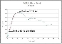
However, we could still see that there was almost no deflection at all until ~30 Nm, and then after that something gives the the material has a much shallower degree vs applied torque yields curve.
You went from elastic to plastic deformation.

No it's not just that, it's an actual rolling motion that was possible after one end tooth broke off at 30 Nm and then there was room for sufficient displacement that overall shape of the opening could change, allowing the axle to turn without actually shearing off any additional teeth. That's what I was trying to emphasize. If you look at the actual shape of the torque vs. displacement curve at this point it's not a normal case of transforming form elastic to plastic deformation.

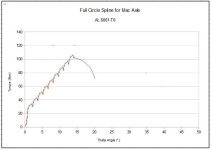
The results with an identical aluminum torque plate interface but constrained so that the axle stayed in same central axis as the torque plate didn't show this, and went right up to 120 Nm before there was any plastic deformation. Then when it did fail, almost all the teeth sheared. I'll do another example where the arm is just pulled steadily to failure rather than pulsed to failure.

What type, temper and thickness of Al are you using?

It's 6061 T6, 3/16" thick, but not because that's a material we plan to use. This is just sacrificial testing to see relative strength of various designs when the material is held fixed, and then once the design is optimized we'll see what material is then most suitable. If it can be Aluminum (perhaps 7000 series), then that would be great just because we can more easily do all the fabrication in house.
 
teklektik said:
justin_le said:
But you can see that there is still some skewing on top and bottom of the 'U' as a result of twisting force at the 180 degree bend.
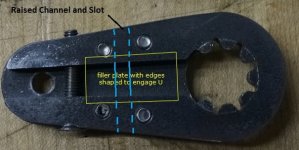
Thinking back to AmpedBikes TAs - perhaps the skewing could be reduced if the inner edges of the U were shaped to engage a matching filler plate. Unlike the shaft, the TA parts are laser cut, so there are many shaping options for the serrations to minimize redirecting forces in undesirable directions.

That was exactly our next line of design exploration! We hadn't thought of doing something serrated on the inside edge like that, but rather having a single perpendicular channel in the backing plate and a corresponding protruding ridge in the 'U' channel. These would nest into each other and lock the arm against any shearing motion between the top and bottom of of the U.

Torque Arm Channel Idea.jpg

I think this is pretty much what Fechter was referring to with this suggestion earlier:
fechter said:
Some tab/slot feature that prevents skewing independent of the bolts might be good.

On a different topic:
e-beach said:
I agree with Buk 100% on this one. The splines are cute and if I were a splined lever I might even ask yours out on a "splined-date."

I just might accept ;)
However, flats with rounded corners would be more robust and easier to make. Something similar to a bottom bracket axle and crank.

I haven't ruled out attempting a square interface either, it was just from experience that it's hard to have a square interface that can easily pinch to have zero play at all. With this splined arm, you just need to tighten the pinch bolt a tiny amount and the torque arm becomes completely locked to the axle with zero slop even if you rock it back and forth with 100 Nm.

I have a hard time seeing a square axle (with one end open for the cable exit) locking things this well without developing some play over time. If you take a tight fitting square with rounded corners and rock it back and forth with 100 Nm, you get a looser fitting square.

But it does merit a try since it would be easier to achieve compatibility across manufacturers. Your example of bottom bracket axles is on point though, since all modern BB's have completely done away with square interface and are now splined for a reason.
 
Chalo said:
Alan B said:
A 100 kg rider standing on a 170mm crank arm pedal produces about 160 Nm of torque on the rear wheel with 1:1 gearing which is common in mountain bike drivetrains, unless my arithmetic is broken. Why would 200 be out of bicycle range?

Because it isn't applied at the dropout. The torque gets resolved as chain tension, which is much easier for a truss frame to manage.

Point is that 200 Nm IS in the range of forces that bikes deal with every day.
 
Alan B said:
Point is that 200 Nm IS in the range of forces that bikes deal with every day.

The only parts of the bike that see that amount of torque are the crank arms, spindle, and rear hub.
 
justin_le said:
I'm surprised that the torque arm on the copenhagen wheel is described as "loosely fitted". By that do you mean it's loose on the axle with a hex interface, or more that the way it secures to the bike frame (just with a single hoseclamp) is somewhat loosely defined?

The arm is fitted with a hex hole over a hex shaft section, but it has enough clearance that it can skew to meet the frame without being bent to fit.
 
justin_le said:
.......I just might accept ;)
.... :shock: .... :oops: ...... :lol:


e-beach said:
However, flats with rounded corners would be more robust and easier to make. Something similar to a bottom bracket axle and crank.

I haven't ruled out attempting a square interface either, it was just from experience that it's hard to have a square interface that can easily pinch to have zero play at all.
That sounds to me like production tolerances. Crude tolerances wouldn't function for your needs. Or more then 4 flat sides might work out better.

With this splined arm, you just need to tighten the pinch bolt a tiny amount and the torque arm becomes completely locked to the axle with zero slop even if you rock it back and forth with 100 Nm.
But not at 200Nm. I supposed a hardened steel test is next. But that would be harder to clamp due to hardness/brittleness, would it not?.

I have a hard time seeing a square axle (with one end open for the cable exit) locking things this well without developing some play over time. If you take a tight fitting square with rounded corners and rock it back and forth with 100 Nm, you get a looser fitting square.
And splines will never develop play over time? As I understand it all steel, under load stretches over time.

Close tolerances would have to be strictly adhered to with a square interface. However, your points on this matter are leading me to believe that a pinch bolt for a square interface should be as close to the center of the axle as possible to eliminate as much uneven pressure to the clamping effect.

But it does merit a try since it would be easier to achieve compatibility across manufacturers. Your example of bottom bracket axles is on point though, since all modern BB's have completely done away with square interface and are now splined for a reason.

As far as I can tell the splined BB axles are splined to (mostly) lock in product sales. If a spline is proprietary then one always will have to purchase the manufactures proprietorially splined product.

After 12,000 miles on my now dead Liahona I did wear out the square taper Shimano crank on the left side of the bike. It is the side I generally initiate the bike movement with, as I usually use my right foot for support at stops. My whole body pressure as I started from a dead stop wore it out over time. The fix was easy though. I went to my local bike coop (the Bikerowave) and got a used replacement for a couple of dollars. A splined replacement would be harder to find and I might have to buy a new replacement. I don't know how long it takes for a splined crank arm to ware out, but my square tapered one took a long beating before it finally got too loose to pedal.

On the other-side. Repeat business keeps a bike shop in business.

:D
 
justin_le said:
That was exactly our next line of design exploration! We hadn't thought of doing something serrated on the inside edge like that, but rather having a single perpendicular channel in the backing plate and a corresponding protruding ridge in the 'U' channel. These would nest into each other and lock the arm against any shearing motion between the top and bottom of of the U.
Am I missing something, or is there a reason you can't make the arm one piece, with the backing plate and the elongated "c" plate as one piece of material, and simply machine the channel into it?

Wouldn't that prevent the C from deforming in the "belt-like" fashion it does as a separate piece?


EDIT: Nevermind, I just realized that would prevent the pinch bolt from being able to re-tighten it around the axle splines. :/
 
amberwolf said:
Am I missing something, or is there a reason you can't make the arm one piece, with the backing plate and the elongated "c" plate as one piece of material, and simply machine the channel into it?

Yes, I mentioned the main reason for that in my 3rd post:
justin_le said:
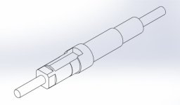
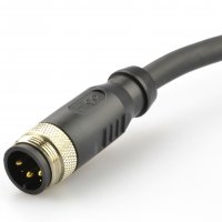
One other constraint we had in the design is that the torque arm plate had to install over the axle with a connectorized cable already coming out of the motor, which means that the splined interface piece has to be 'U' shaped. A complete circle wouldn't work as then there would be no way to pass through a large overmolded motor connector plug through the splined opening of the torque arm.

If the motor cable connector was installed after the torque arm was on the axle, then you could get away with just a small curve to accomodate the cable. But if we want it to work with one of these L1910 Overmolded Connectors then either we need a 19mm diameter open circle in the torque arm that the connector can pass thru, or it has to be slotted like a 'U' with an opening the same width as the cable diameter, around 9mm.

45A%20motor%20connector%20male.jpg


Wouldn't that prevent the C from deforming in the "belt-like" fashion it does as a separate piece?

It totally would, and does as you saw from the tests where we had it in a solid piece.

EDIT: Nevermind, I just realized that would prevent the pinch bolt from being able to re-tighten it around the axle splines. :/

There is also that too. The pinching isn't strictly necessary but it enables us to deal with a much wider tolerance variation between manufacturers and batches, and still have a perfectly snug arm without play. The idea is that you pinch it snug with the pinch bolt, and then lock the plate in place at that tension with the 4 face bolts so that the pinch bolt itself is no longer strictly needed. Once this is done, the arm basically stays on the motor axle, there is no need to take it off except when you need to open up and disassemble the hub motor.


e-beach said:
With this splined arm, you just need to tighten the pinch bolt a tiny amount and the torque arm becomes completely locked to the axle with zero slop even if you rock it back and forth with 100 Nm.
But not at 200Nm.

No, but the goal was 200 Nm to failure, not to "no detectable yield"! 100 Nm with zero yield or shifting is quite amazing in my books, given how a conventional slotted axle and torque arm behaves at these levels. I think that what I need to do next here is test some conventional torque arm designs with flat axles using this datalogging test jig so that people have a better reference point.

I supposed a hardened steel test is next. But that would be harder to clamp due to hardness/brittleness, would it not?.

With mild steel as you saw in the last tests we're already well above the torque requirements, so I wasn't seeing any need to experiment with hardened steel at this stage.
 
justin_le said:
If the motor cable connector was installed after the torque arm was on the axle, then you could get away with just a small curve to accomodate the cable. But if we want it to work with one of these L1019 Overmolded Connectors then either we need a 19mm diameter open circle in the torque arm that the connector can pass thru, or it has to be slotted like a 'U' with an opening the same width as the cable diameter, around 9mm.

45A%20motor%20connector%20male.jpg

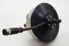
Install the HIGO-L1019 as a side entry and all problems associated with the motor-cable-through-axle magically disappear. Shown here is a MacFat front drive unit from my AWD :mrgreen:
.
MacFat 1.JPG
.
 
teklektik said:
The reference is about using the laser cut serration concept in flat stock to create parts that interlock to resist movement.

Okay, but remember that laser cutting leaves an ~375 micron gap between the parts. (Sorry if you know that, but the general public see "laser" and think 'pin point accuracy' ;) ) And even saying '375 microns or 0.375 mm doesn't bring the effect of that gap into focus.

On that part, if they tried to use both the inner and outer pieces from the same piece of stock, then it results in 0.75mm of translation slop, and that translates into a gnat's under 2° of rotation slop:
junk46.jpg

And if you're old enough to have ridden a bike with worn cotter pins on the cranks, you'll know that results in a huge shock loading every time the the drive is engaged.

They would have to make the inner and outer splined parts from different profiles and different pieces of stock.

Even then, when you factor in the 50 microns of tolerance for laser cut accuracy, doubled to give a fit of -50µ/+0 & +0/+50µ, that shape of tooth, and every other shape you might choose, results in two points (lines in 3D) of contact, giving rise to 'infinite force' loading a the initial point of contact, rapidly deforming to an area contact, with the size determined by the ductility of the material.

The point I'm making here is that even with laser cutting, splined parts still don't distribute loads across more than 2 points of contact.

In the following image, there are close-up zooms of the point of closest approach between 3 adjacent pairs of spline teeth showing that when the inner part is rotated by 1.992°, 1 tooth (in the middle below) contacts (interferes), but the two teeth either side do not (quite):
junk47.jpg

Now the package doing that drawing uses double precision floating point (51digits of binary precision), which at the scale of this drawing (~25mm OD), means that the math is accurate to less than an attometer (otherwise known as an angstrom). Even with the cumulative errors from the 6 rotations used to construct the model, and rounding to the nearest pixel, this image (before resizing for posting) was accurate to less than a nanometer, and still one pair of teeth contact before any others.

If their primary purpose is intended to reduce bearing/shear stresses by spreading the load over 20 points; splines like this buy you almost nothing.
 
justin_le said:
Buk___ said:
You went from elastic to plastic deformation.

No it's not just that, it's an actual rolling motion that was possible after one end tooth broke off at 30 Nm and then there was room for sufficient displacement that overall shape of the opening could change, allowing the axle to turn without actually shearing off any additional teeth. That's what I was trying to emphasize. If you look at the actual shape of the torque vs. displacement curve at this point it's not a normal case of transforming form elastic to plastic deformation.

If you sheared a tooth, you definitely went from elastic to plastic; and then way beyond.

After that, the addition degree(s) of freedom meant that the fulcrum effect of the next two teeth to contact applied the load in a direction that caused plastic deformation in the U-shaped TA; basically levering the sides apart and due to the opposing fulcrums, distorted the head of the U, so that the sides translated in opposite directions.


justin_le said:
The results with an identical aluminum torque plate interface but constrained so that the axle stayed in same central axis as the torque plate didn't show this, and went right up to 120 Nm before there was any plastic deformation. Then when it did fail, almost all the teeth sheared. I'll do another example where the arm is just pulled steadily to failure rather than pulsed to failure.

I would interpret your torque/theta graph somewhat differently. I believe it shows the transitions from elastic to plastic many times as each new pair of contact points come under load as the previous exceed the yield point and shears:junk48.jpg

At each of those red circles, there is a transition in the forces. Initial a sharp reduction, then a steady build leading to the next red circle. My interpretation of that is each circle is where the elastic limit of one tooth is exceeded, it shears, there is a drop in torque as the shaft rotates a few minutes of arc until it connects with the next tooth.

Then the elastic limit of that tooth fields the force, and the tooth stretches sidewise until it reaches the yield point and the process repeats. I count 10 red circles for 10 pairs of teeth.

(There is also something going on in the green circle at the start of loading? Could be the strain cell loading up, or slack in the system.)


I suspect (would put money, but don't have access to the equipment to perform the test to prove it). that if you could apply the torque very much more slowly and steadily, and if the resolution of your stress.vs.strain graph was higher, you would see a graph something like this:junk49.jpg

Of course it is an idealised representation, but basically:

  • the stress/strain rises steadily at a slope equaling the materials modulus of elasticity;
  • the yield point is exceeded and the slope lessens as you transition through the plastic range and the material permanently deforms;
  • the shear plane finally lets go and the tooth shears;
  • the torque drops and the rotation increases suddently as the shaft rotates to the point that the next pair of teeth engage;
  • the graph returns to the Young's modulus slope because these new teeth have yet to experience any stress;
  • the process repeats until enough teeth have sheared to allow the shaft to rotate freely.


justin_le said:
What type, temper and thickness of Al are you using?

It's 6061 T6, 3/16" thick, but not because that's a material we plan to use. This is just sacrificial testing to see relative strength of various designs when the material is held fixed, and then once the design is optimized we'll see what material is then most suitable. If it can be Aluminum (perhaps 7000 series), then that would be great just because we can more easily do all the fabrication in house.

Understood about it's sacrificial nature.

However, without labouring the point, even if you get a 7000 series part to survive the torque test, I'd still caution against it. Even if you went to 7075-T6 with its ~450MPa yield strength, it will still embrittle with cyclic nominal loading; and will fail! And at a loading far below the T6 critical value.

I get the ease of manufacture point, but trade that against liability?

I can do no better than link and quote this again.
 
e-beach said:
As far as I can tell the splined BB axles are splined to (mostly) lock in product sales. If a spline is proprietary then one always will have to purchase the manufactures proprietorially splined product.

Amen to that!

What's the betting that Hollowtech III (Octalink V3) has slightly wider splines and slight longer grooves; and is not compatible with anything that went before it. But it'll weight 2.023g less, so it'll be a must-have amongst a larger portion of the lycras. (And it'll cost 20% more again.)
 
Buk___ said:
The point I'm making here is that even with laser cutting, splined parts still don't distribute loads across more than 2 points of contact.


If their primary purpose is intended to reduce bearing/shear stresses by spreading the load over 20 points; splines like this buy you almost nothing.

Buk buddy, these parts are not being made from carbide and diamond!

The torque arm and axle metals are ductile, not brittle, and deform at the contact until the total contact area is large enough to bear the force. At 100 Nm there is 2600 lb of force at the contact radius on this 17mm axle, and with that much force you can be quite sure that the load is uniformly spread across the teeth. Even if the machining (not lasering, fwiw) was off and one tooth initially had most of the contact, that contact patch would almost immediately deform until other teeth or splines are making contact and things get distributed. And it does this well before actual shear failure of any tooth.
 
With my apologies to Justin and the rest, this thread has my interest piqued.... so here is my 2¢ again.

This is what I am thinking now.

From the photos of the failures it looks to me like the first spline at the gap is the one that is getting the most deformation due to the gap in the u cut of the torque arm. It looks to me that arched splines are not locking in to place well. Perhaps they are contributing to the torque arm failure by allowing an "easy movement" due to the rounded tops of the splines.

I have been looking at drive shaft splines today and none of them are arched. They are all flat. However that gave me another notion.....

What if the axle was cut with a chamfered slot in a way that the the torque of the motor or breaking forces actually tightened the u in the direction the torque arm is being tugged, as apposed to separating it the way an arched spline would. A chamfered slot would hook the torque arm instead of allowing seperation.

The rounded nature of the axle would also allow for type of cylindrical clamping pressure that Justin was desiring.

I didn't get the cad drawings just right but between the three jpgs you will probably get what I mean. Camforeslot.JPG
Axle with lock bevels 1.JPG
Axle with lock bevels2.JPG

:D
 
Dovetail groves, that's what I was thinking about.

Edit:
lock axle 2.JPG
lock axle torque arm example.JPG
Lock axle assembly 1.JPG
:D
 
justin_le said:
Buk___ said:
The point I'm making here is that even with laser cutting, splined parts still don't distribute loads across more than 2 points of contact.


If their primary purpose is intended to reduce bearing/shear stresses by spreading the load over 20 points; splines like this buy you almost nothing.

Buk buddy, these parts are not being made from carbide and diamond!

The torque arm and axle metals are ductile, not brittle, and deform at the contact until the total contact area is large enough to bear the force. At 100 Nm there is 2600 lb of force at the contact radius on this 17mm axle, and with that much force you can be quite sure that the load is uniformly spread across the teeth. Even if the machining (not lasering, fwiw) was off and one tooth initially had most of the contact, that contact patch would almost immediately deform until other teeth or splines are making contact and things get distributed. And it does this well before actual shear failure of any tooth.

Okay. Good luck with your product.

(But... have you ever used a reamer?
s-l1000.jpg
)
 
phinaillee...found the only image in existanz on da wenb of what the a4 mentioned dopenvagen wheel wuz using.
(piquet my nelson quriosity.)

tech-copenhagen-wheel-advanced-self-diagnostic.jpg


as for square taper (or even splined) is there anything useful 2b interpolatef from existing crank-arm/bb axle torque info?
if chalo wuvs u as much as his tagline claims he shud have that kind of info right at his fingertips & pull it out of his 1010 0101 0101.
or have you considered doing torque testing on a ground down sqare taper bb axle to save wear & tear on your proto axle?
 
Alan B said:
It would be interesting to see some reference testing with a standard flatted axle to help calibrate/compare to what we are accustomed to.

+1

Looking forward to a "control" grouping of info on what is normally used. What I would really like to see is the test in a standard MTB frame with a conventional (Girn?) rear torque arm as a reference.

@Toorbough ULL-Zeveigh
Nice look at that wheel. Could it take 200 Nm?

:D
 
Back
Top