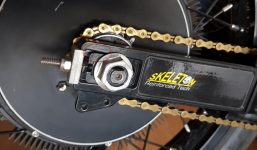
Merlin said:What's wrong with the(normal flat axle) clamping dropouts we are using on the "big bikes"?
<Snip>
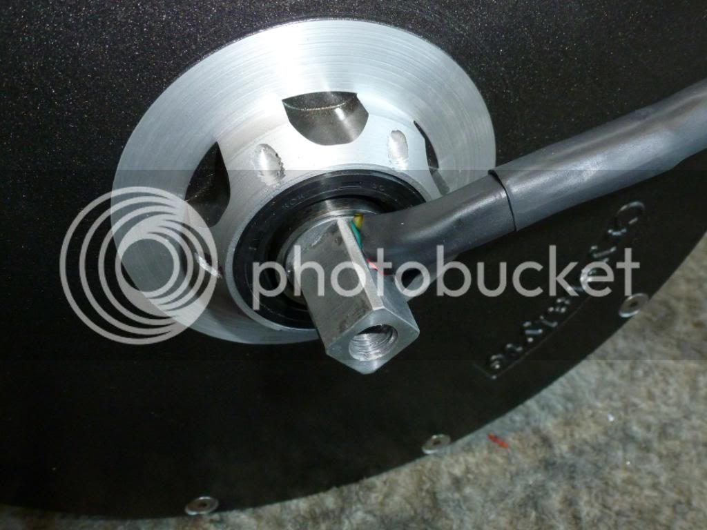
if I had a wish I would prefer an "update" about how the wires comes out of the motor. It's always shitty with the disc brake.
Always needing disc Spacers... Extend the brake bracket... Making it more flexing....
If you look at the original posts, that's a part of the reason for this new idea/testing: To leave the threaded axle itself the correct size to remain centered in the dropouts where it needs to be, to fit brake calipers where they are designed to be and end up correctly placed on the rotors.
It also ensures the dropouts never take the twisting load directly, so even if the torque arm fails to prevent axle rotation, the wheel should at least stay on the bike (which it doesn't always in a twisting failure that destroys dropouts, allowing teh wheel to be able to come off the bike entirely).
While that won't help if the axle actually snaps, the snapping is less likely to happen in the first place with a torque arm inboard of the threaded area, rather than within the threaded area, outboard of the stress riser at the start of the threaded area/shoulder.
Regarding the wire exit, I'd personally prefer to see a much larger ID bearing, with a "filler" ring that allows the wires to come out well outside the axle itself. Would allow a stronger axle, larger wire gauge, and separating hall and phase wires (these could even come out individually), and even allowing pretty much as much instrumentation wiring as desired, and even space for liquid cooling pipes or other "exotic" modifications.
")
Unfortunately this won't work with a rear wheel that has a disc brake *and* a cassette or freewheel. It can work on a front wheel, or on any rear wheel that has only a disc brake *or* a cassette/freewheel (the side without one can then be used as the wire exit side with the large ID bearing).