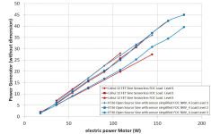
Sine VS Square wave efficancy?

some more info:

Quite soon after building the v1.00 chip I figured out that matching the backemf of the motor is not what you want.
Think about it, you don't really care about what the output voltage of the controller looks like. What you want is ripple free power delivery by the motor, no high frequency torque ripple or the noise from this.

clean_no_5th.jpg

Above is what I mean, the three curves in the bottom are the power delivered by each individual motor phase, all 3 add up to the straight line at the top of the figure. Straight ripple free power delivery is what you want.

with_5th.jpg

The picture above is what you get when you drive a trapezoidal motor with a sine wave controller. The trapezoidal motor is modelled with 5th order harmonic only (there's also 3rd which cancels out, 7th etc etc). You can see power delivery is not constant anymore but has a high frequency sine wave on top.

Now what you really want is to get rid of this sine wave shaped power delivery, and to do so matching the backemf of the motor doesn't help.
The sine wave has a very high frequency by the way (6 times the electrical frequency) and is typically not as bad as shown here, but still...

Getting rid of one harmonic, like the 5th as mentioned here, is relatively easy but what I want is to get rid of the 5th and 7th in one go...

all this is extremely nerdy stuff, but it's cool and fun to play with.
 
v2.21 outputs sine waves (with moving midpoint)... I got distracted by the business of adding the
recovery (which is a good thing as it was interesting and enables the use of multiple controllers
running a single motor)
 
Many people got it wrong when talk about "SINE" controller, the correct term should be VFD (Veriable Frequency Drive), there are actually 2 different family of VFD controller, one is FOC (under Vector Control Family),which calculate the orientation of the magnetic field on the rotor, and drive the motor 90 electric degree from it's current angle. Anther type is Scalar Controller, it get's the motor speed signal from hall sensor and try to drive the PWM by a sine table to get sine effect, but it does not care about the rotor magnetic field nor stator flux, it use similar agorythem as the VF inverter.
Most of those CCB controllers (China Cheapo Brand) are scalar drive, and they try to confuse people with "SINE" drive advertising... true FOC drive doesn't care about if your motor is true Sine or not, it will just drive the rotor at 90 electric degree from its current position.

As for the question of FOC vs Trap, from our research, Trap do provides better torque for start up, and better / higher speed for field weakening. As for FOC, it provides most smooth operation, amazingly, from our research, the total loss of Trap and FOC on hub motor, FOC is only slightly better, Trap drive puts all the energy loss on the motor, and keep the controller temp low, as for FOC, the controller heat up easily, but the motor is still rather cool. The controller I made could switch FOC and SSD (Six Step Drive) on the fly (which vehicle is running), when switching between FOC / SSD, than can see the difference clearly.
 
Shenta,
I you have done this research, do you have any published results to provide so we can evaluate your statements?

It does not do any good to show simulated results for sine drive. What is needed is actual phase drive waveforms for a 360 degree wave cycle AND also show the Bemf waveform for the same RPM. Bemf should be done with the motor mounted in a lathe (or some other very constant drive RPM). If more than one RPM result is provided, then we can see the phase distortion. We should also be shown (using a Hall as a tic marker) what the phase advance (or retard) is for identical either drive phase or Bemf phase.

After all, this is the real world and a picture is worth one thousand words and shows conclusive results. Otherwise all we are getting is alot of talk. It sometimes seems that when we really need to see if one approach is better than another, the magic word PROPRIETARY immediately pops up.

For example, look up the paper entitled 'Torque Maximization Control of 3-Phase BLDC motors in the High Speed Region' from Pusan national University. That is both simulation and experimental results. We need many more papers like this.
kenkad
 
kenkad said:
Shenta,
I you have done this research, do you have any published results to provide so we can evaluate your statements?...

Hope this picture validates your question:
%E6%96%B9%E6%B3%A2%E9%A9%85%E5%8B%95%20vs%20%E5%A4%B1%E9%87%8F%E6%8E%A7%E5%88%B6.jpg

for SSD, there are also different ways to drive them, eg: 2 phase drive or 3 phase drive.
You may want to do some more reading about the different ways to drive a 3 phase PMSM motor.

For Centralize winding, it is best to use FOC control, as for distribute winding, SSD maybe the best, but still depends on BEMF.


oh, yes, the Korean has alot of research on PMSM motors, and they also have many secret projects from the north too:
1326298014-1556736726.jpg
 
fyi, we discussed efficiency for the adaptto controller during our podcast (@ 38:45).

not sure how it affects efficiency, but i found it interesting andrey said at 41:16, "when you use sine wave, you use all three windings at the same time. if you use block controller, at one time you use only two windings."

PS: he mentions is that the main feature of the adaptto controllers was not the fact that it used sine wave, but that it was easily programmable...
 
Driving all three phases is referred to as 180 degree modulation. The exception is at the zero crossing points, where only two phases are driven. Square or trap is 120 degree modulation. If you want to see 180 degree sine modulation, look at the second thread attachment in the 'Regeneration ...' thread I tried to get started. All controller manufacturers who say they are doing sine wave drive should state absolutely that they are doing 180 degree modulation. Some sine wave controllers are in fact 120 degree modulation.
kenkad
 
I had hoped to get a sine wave controller but ended up using a KT square wave 11a - 22a peak version on a little 350w mxus. Im not hearing ungodly noises sucking power from the battery. I am hearing the whir or high pitched hum of the gears making me think their harmonics losses are greater then the square waves harmonic losses.
I was surprise by the square waves quietness on the XOF7 motor, I imagine a sine wave would be quieter the square was not bad in this case.
It may be a tweaked square wave controller not square not sine but some other type of wave
 
On our OpenSource firmware for KT Kunteng / BMSBattery controllers, sinewave version, we did the firmware from the start and we can optimize to max efficiency and torque possible -- we are testing against other controllers and the original firmware and we have good results:

https://opensourceebikefirmware.bitbucket.io/


Attachments

  • 94-3.png
    94-3.png
    166.7 KB · Views: 3,137
Drunkskunk said:
But Phase A is up, is relying on Phase B and then C for ground. With a Sinus wave form, you never get a good ground, you're almost always in transition. That might be fine for reducing noise, but it means the Dropping phase is still falling through the transition of both the other phases, and that can't be good for efficiency or power delivery.
I think you've got that a bit backwards.

"Sine wave drive," although it's somewhat new for ebikes, has been used since the first electric motors came out. One of the characteristics of a three phase sinewave motor drive is that the vector current is always the same; the motor always sees the same field. Compare that to a square wave drive where there are hard transitions where the motor current drops out then returns.

Driving all three phases is referred to as 180 degree modulation.
Both square wave drives and sine wave drives offset each phase by 120 degrees.

not sure how it affects efficiency, but i found it interesting andrey said at 41:16, "when you use sine wave, you use all three windings at the same time. if you use block controller, at one time you use only two windings.
Sort of. In a delta wound motor, when the voltage between phases A and B is the same, you don't see any current in that phase (or more accurately no induced change in current, which is what's important.) In a sine wave drive that happens periodically but lasts a short time since the phase relationship is always changing. In a square wave drive that lasts a longer time. However, in a wye wound motor that's not true, since current will keep flowing through all three windings even when A and B are at zero volts and C is at battery voltage.

Also, the above is very oversimplified, since back EMF keeps voltage changing (and current flowing) through all three phases constantly.
 
The kt controller Im using is the z version apparently it stands for z wave now Im not sure on this but it appears the "sine wave" version of the kt controller may be a modified type of square wave as well . This is what a few members deduced from looking at the the wave forms on a display. One person who owns one said it was a sine wave but was noisy at start up and quieted down later in rpm. That does not sound like a sine waves description or does it ? as I have been reading they are quiet at start up.
 
Here is a simple explanation that hopefully everyone can understand.

A. Trapezoidal commutation generates torque ripples at low speeds and is relatively efficient in the high speed range. Noise takes energy to make and the louder it is the less efficient it is. Trapezoidal control is relatively simple and inexpensive.

B. Sinusoidal commutation provides smooth operation at low speeds, but it is inefficient in high speed range. Sinusoidal is more complex and expensive than Trapezoidal.

C. FOC (Field Oriented Control) gives the best of both trapezoidal and sinusoidal commutations – smooth operation at low speed and efficient running at high speed. Of the three options, FOC is the most complex and expensive.

Just FYI, the above info came from: https://pdfs.semanticscholar.org/40ac/06d3db0b82242038c2dcd20c433d5d1c74f6.pdf. I added a few comments.

Which one is more efficient...just like any question, the best answer is "It Depends", until all the variables are defined.

If Trapezoidal is not the best then why is it used...COST and for most applications it gets the job done. When you investigate why things are the way they are, cost will usually be the reason/answer.

Is my explanation too simple :D ?
 
FOC (or sinus current) drive isn't a high speed penalty for a controller that has the processing speed to run the more complex current control loop at high speeds. FOC unlocks the ability to leverage "field weakening" (commutation timing advancing with RPM increase) to have substantially more top-end (>30-80% more useful RPM range) than is possible with trap-wave block commutation.

Even for a dragster application where system efficiency may not be an important metric, FOC still enables massive advantages on the back half of the track.
 
liveforphysics said:
Gab said:
Do Kelly make ebike sinewave controllers ?


I've personally only seen Kelly sell shit in a box that looked similar to something that could be confused for a controller to the untrained eye. ;) :pancake:

Are they still the shitsstink?
Whata bout them Powervelocity or Greentime.

I def want a Sinewave with Regen for braking. Silence is key for me.

Of course the http://adaptto.envolt.se/Products/Controllers/ would be great if we had the cash on hand.
 
I haven't taken apart a Kelly controller for a few years, so I can't comment on the current state of design. The models I had experience with a few years back were un-inspiring performance for a brief period before converting to plasma. Hopefully things have improved from that point in the last few years of MOSFET and micro-controller tech evolving rapidly.


markz said:
liveforphysics said:
Gab said:
Do Kelly make ebike sinewave controllers ?


I've personally only seen Kelly sell shit in a box that looked similar to something that could be confused for a controller to the untrained eye. ;) :pancake:

Are they still the shitsstink?
Whata bout them Powervelocity or Greentime.

I def want a Sinewave with Regen for braking. Silence is key for me.

Of course the http://adaptto.com/ would be great if we had the cash on hand.
 
Comparative efficiency was measured in the PhaseRunner thread, and it was found that the FOC PhaseRunner was slightly more efficient than trapezoidal commutation.

One simple way to think of it is the trapezoidal commutation jerks the magnetic field every 60 degrees, so it is only properly aligned for max torque at the center of that range, the rest of the time it is slightly off (by the cosine of the angle). The FOC rotates the field smoothly and maintains the optimal 90 degree relationship between the magnetic fields and generates smooth torque. The switching losses of FOC are a bit higher, the magnetic efficiency is a bit higher also. So the details matter in who wins out. Theory alone can't really tell you.

Anyway, Justin has some nice graphs of the comparisons in his usual detailed way.

The FOC controllers I have are so much nicer to drive I would use them even if they were a little less efficient, but they are apparently a little more efficient, and that's excellent!

Watch out for the scalar type sinewave drives, they often claim to be FOC when they are not, and their efficiency drops off at high RPM. They are a small step up from trapezoidal, just a minor firmware change with lookup tables, but they are a pretty big step away from full FOC. FOC drives (for ebikes) generally have 32 bit computational power and actually measure motor current in real time to compute where the rotor is.
 
markz said:
liveforphysics said:
Gab said:
Do Kelly make ebike sinewave controllers ?


I've personally only seen Kelly sell shit in a box that looked similar to something that could be confused for a controller to the untrained eye. ;) :pancake:

Are they still the shitsstink?
Whata bout them Powervelocity or Greentime.

I def want a Sinewave with Regen for braking. Silence is key for me.

Of course the http://adaptto.envolt.se/Products/Controllers/ would be great if we had the cash on hand.
You can go with with Kunteng motor controllers and our OpenSource firmware were we implement "low resolution FOC" -- see our notes about our FOC implementation:
- efficiency comparison: https://opensourceebikefirmware.bitbucket.io/development/s_and_application_notes--Endless-sphere.com_forum_messages--2017.09.15_-_our_OpenSource_firmware_efficiency_compared_to_Lishui_12_FET_FOC.html
- tecnhical implementation details: https://opensourceebikefirmware.bitbucket.io/development/Datasheets_and_application_notes--Endless-sphere.com_forum_messages--2017.10.23_-_FOC_and_no_FOC_comparison.html
 
Alan B said:
They are a small step up from trapezoidal, just a minor firmware change with lookup tables, but they are a pretty big step away from full FOC. FOC drives (for ebikes) generally have 32 bit computational power and actually measure motor current in real time to compute where the rotor is.
So Kunteng runs on 8 bits computational power and measure motor current in real time to compute where the rotor is, but I call it "ver low resolution FOC", still the results are good: https://opensourceebikefirmware.bitbucket.io/development/Datasheets_and_application_notes--Endless-sphere.com_forum_messages--2017.10.23_-_FOC_and_no_FOC_comparison.html
 
I have been study Solar inverters lately it seems the solar sine wave inverters are usually rated at 90 to 96% efficient with rarer high Amperage models reaching 98% efficiency in DC/AC conversion.
Noticed square wave is advertised at 80% efficiency , modified sine wave as often called is marketed as 90% efficient.

This video demonstrates that square wave starts out rough/ noisy and smooths out as frequency is increased.

[youtube]uIuJTWS2uvY[/youtube]
 
eCue said:
This video demonstrates that square wave starts out rough/ noisy and smooths out as frequency is increased.
That's due to the (probably unintentional) filtering provided by the signal generator and test setup.
 
The above experiment is invalid, disregard it.

A square wave contains the fundamental sine wave and all the odd harmonics in decreasing amplitude.

The even harmonics are not present.

The ear cannot hear many of the harmonics (except at very low fundamental frequency), and as mentioned above the generator and oscilloscope used have limits also that are quickly reached as the fundamental frequency increases.
 
liveforphysics said:
I haven't taken apart a Kelly controller for a few years, so I can't comment on the current state of design.
They still brick themselves if plugged into the programming port while the motor is rotating, so I'd call that part at least poor design.
 
I see a correlation between the test and the noise square wave controllers output at start up or when over loaded and stalling , at higher speeds they sound quiet without a noticeable noisy timing issue.
 
Back
Top