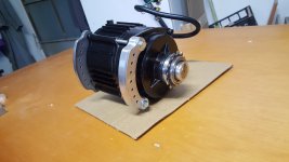
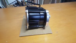
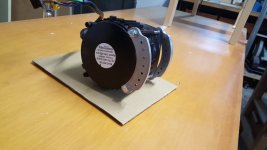
mr.electric
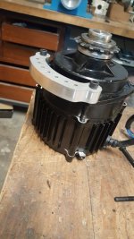
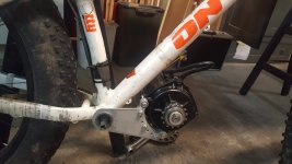
10 kW
whatever happened to open source and es being the free sharing of ideas to move ebike forward. I for one celebrate Minimums sharing. Awesomeness. Its about time.
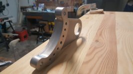
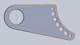
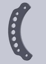
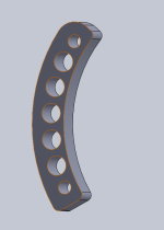
Skaiwerd said:The ideal design to me would be to have a tab added to your motor mounts and have receiving brackets on the bike frame. This would make it so that you don’t need to mount to your bottom bracket.
Skaiwerd said:Has anyone brought the motor in closer to crank center than the stock position? Even a little closer could make the motor position more compact for in frame installs, or tight in a non technical term


I would append to this list: driving sprocket (cog) engagement length (well, angle actually) to the chain. Simply put - longer is better as more teeth will be engaged. Especially important if motor cog is small and/or driven sprocket large.jonnydrive said:Nearing the motor to the crack requires to pay attention to two things:
- do not make the engine the lowest thing after the bike wheels (like the bafang) hitting a rocks with the motor may damage it
- limiting the chainring size
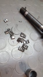
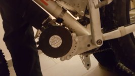
I have thought about second tensioner on upper side. Limited travel (up to 10-15mm) and very high tension using either disc springs or similar. When full throttle is applied, upper tensioner acts as dampener. Lower tensioner would be needed as well to counteract and to compensate for any slackness.Now I'm figuring out to reinforce the rear hub freewheel, I have broken two fat-bike freewheel hub. Once solved the motor support, the bike transmission is the weakest point of my build to face out.....
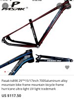
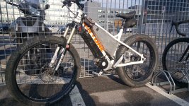
Skaiwerd said:I’m working on an aluminum frame cyclone3000 now. You can get a $140 with shipping, 29” frame from AliExpress and put 27.5” x 3” tires will fit. I’m not into the fat bikes but the 3 inch tire bikes is my current direction. It’s also aluminum and I’d really like to put the motor in the frame with no welding. I think I’m going to get the frame soda blasted first to remove the paint and graphics. See I can share. I priced American steel frames (for welding and the ride) and it was over $1000 + shipping. Or Canadian for $800 plus shipping. Pretty much the same features with the Asian frame and it’s super light.
minimum said:I have thought about second tensioner on upper side. Limited travel (up to 10-15mm) and very high tension using either disc springs or similar. When full throttle is applied, upper tensioner acts as dampener. Lower tensioner would be needed as well to counteract and to compensate for any slackness.
jonnydrive said:yep, mee too, the chain without the standard front derailleur jumps sideways, but with two front chainring it is difficult to build a good chain tensioner because the chain needs to move up and down and left and ride to follow the gearings . I built a handmade prototype version, testing will came soon
DingusMcGee said:Skaiwerd,
A Mtn bike frame without rear suspension? I did some steep hill climbing with a Cyclone hard tail and a fat hard tail equipped with the small block LR motor. The gates belt on the LR setup failed on the first attempt at the hill. The freehub pawls soon failed on the Cyclone hardtail. Rear suspension considerably lessens the shock loadings given to the drive train when an airborne spinning rear wheel hits the ground.
What is your reasoning to go with a hardtail?
I have one bike with a 3" wide tire but have no desire to go any bigger again.
minimum said:I have a hardtail, about 1400km since conversion (250-300km in winter). I wish I had full suspension, even when riding only streets.
During winter I broke rear axle riding local forest biking/skiing/jogging trail - which had quite smooth, worked up surface.
Skaiwerd,
. For your 3” tires did you have wide rims like 40-50mm? With that and lower tire pressures the suspension part is less necessary, opinion only. Sure it’s good for thouse who need or want it to match their riding style.
No suspension, high tire pressure and heavy bike (about 35kg: 15kg bicycle, 5kg motor+controller, 15kg battery). Oh, and high speed and bad roads.jonnydrive said:What do you think it is the cause of the broken? The low quality of the components, the absence of a rear suspension or something else?
minimum said:No suspension, high tire pressure and heavy bike (about 35kg: 15kg bicycle, 5kg motor+controller, 15kg battery). Oh, and high speed and bad roads.
Chalo said:minimum said:No suspension, high tire pressure and heavy bike (about 35kg: 15kg bicycle, 5kg motor+controller, 15kg battery). Oh, and high speed and bad roads.
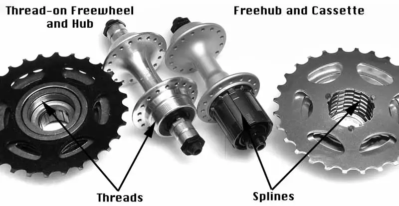
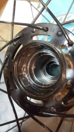
Hubs spaced for 7 speed freewheels routinely bend and break axles even without the extra weight and chain tension of an e-bike. The poor dropout alignment of most cheap bikes makes it almost inevitable.
If you're going to use a mid drive, save yourself a bunch of trouble and get a sturdy handbuilt wheel with a cassette hub.