Help me reinforce this DC to DC step up.

Sunder

10 MW
Joined
Sep 6, 2011
Messages
3,054
Location
Sydney, Australia
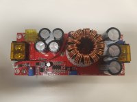
So I melted a 10A rated step up converter with just 2.5A, so now I've bought a 40A version:
20180406_142756.jpg

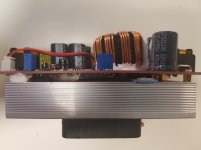
Absolutely Buckley's hope this will handle 40A. I knew that when buying it, but it's worse than I thought. I had intended to upgrade the heat sink on this, but as you can see on the side view, the mosfets are different thicknesses, and so to get them to contact the heatsink, they've torqued the board so hard, it's curved.
20180406_142807.jpg

And that's AFTER the 1mm thick thermal pad to space it out.

So can anyone suggest to me what the best way to improve the current handling capability of this device is? I'm going to see if I can get some copper shims of the right thickness, and put it on a much better heat sink, but aside from that, is there anything else I can do?

Thanks in advance for any advice.
 
I had the bst900 and so I built (designed and plastic printed) a box to help the fan pull air over the heat sink better, that did 15a pretty easy. but didn't have to do that for long on my lifepo4 as the batteries draw tapered away pretty quickly as they fill up.

What about putting high speed fans at the end of the fins and putting a lid on them so that you are forcing air oven the heatsink fins at high speed. Other that that maybe upgrading fets with ones with lower rdson?


https://www.thingiverse.com/thing:2865841

if anyone wants to print their own.
 
Unfortunately nothing like that will help if the FETs aren't in good contact with the heatsink, and I don't know what to suggest to fix it if they aren't.

Maybe it's not as bad as it looks. I'd try running it and checking the temp of the FET tabs with the heatsink if you can get a little thermocouple in there without shorting the two.
 
The copper shims would be likley the best way, as that's very similar to the way things like heatspreaders in laptops and some PSUs are connected to the different-height components under them; this seems to work for those well enough.


If there was any way to mount the FETs vertically so the heatsink could be directly attached to their metal tabs, it would be much easier to extract the heat from them.

Then something like the previously-described air-directing enclosure and forced-air-fan-cooling would help even more than otherwise.
 
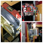
I have what appears to be the same Buck Booster unit. I took the the brute force approach and added extra heatsinks taken from a dead Asus motherboard to spread out the heat. I removed the noisy little stock fan and replaced it with an extra quiet 120mm Arctic F12 PC case fan.

20180408_112121-COLLAGE.jpg

I used thermal epoxy to attach the extra heat sinks. My booster is wall mounted so the the top and bottom are clear to allow room for these additional heat sinks and the 120mm fan. The little stock fan is replaced with an ABS plate but its hard to see in the photos. The plate is held in by the stock fan's extra long screws that go into threaded holes of the stock heat sink. The 120mm fan's hub is then attached to that plastic plate using 3M double sided tape. Then I added hot glue on the long brass standoffs where they contact the 120mm fan's casing. Not pretty but it securely holds the 120mm fan in place. I hope you kept the optional long brass stand offs they gave you!

The thermal conductivity to the additional two Asus heatsinks is good and they're just the right size to fit within the large 120mm fan's air flow. The 120mm fan is barely audible even when the buck booster has it going at maximum speed. It only goes on briefly for 15 seconds or so even when I've maxed out this unit's 1500W to charge my 18s LIPO e-bike. Actually, I wish the 120mm fan would be activated more. The fan is so quiet it could be on all the time without me noticing much.

I'm in process of modifying all my charging equipment to use quiet 120mm fans. The stock little high speed fans are very annoying in my quiet garage environment where I'm also doing other stuff.
 
desolder the mosfets or at least put them upgright and screw them against a heatsink.
 
I'm running the 30a version of this boost converter as one of my main chargers. 48v input to 75.6v 13.2a output (1000w approx).

I've blown 4 or 5 different converters for various reasons. So my own rules are:
- Watch that input current. Factor in the conversion efficiency which is more like 90% for these
- I always power up the input supply to the boost converter, before connecting boost output to a battery. This avoids inrush current from the battery which I think stresses the boost converter.
- I disconnected output of boost converter from battery, before powering off the input PSU
- Try to have airflow around the boost converter. Household fan works well in a garage
 
Hayds13 said:
- I always power up the input supply to the boost converter, before connecting boost output to a battery. This avoids inrush current from the battery which I think stresses the boost converter.

That's an important point! I've done it the other way enough times to know of the "pop" and spark that results. I think it can damage the BMS on the e-bike as well as the booster. My BMS's Bluetooth connection sometimes needs to be reset if I do this. After realizing the potential for damage, I decided to do one more upgrade recently to my charging setup (see photos above).

So I recently upgraded my charging setup with a simple SPST relay on its output. There is as 12V pad you can grab on the booster that will throw the relay to "on" only when the the booster has been powered on. This prevents the inrush current to the booster if I connect the bike to the booster's output before powering on the booster's input supply.
 
Like said above power up first to the correct voltage before connecting the battery or it will blow, unlike the BST900w that you don't need too, and treat the trim pots easy as I have had 3 fail on me turning them to much.
 
Back
Top