connecting five-wire ebike LED display to apparently uncompaible controller

clksoft

100 µW
Joined
Apr 17, 2011
Messages
8
Hello,
I tried to find a wiring diagram to help me in the ***controller information links*** thread but could not find a diagram that would solve me problem. So, I'm posting this in case someone has dealt with the same issues already and is willing to give me a hand.

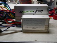
I bought the following controller on ebay to replace a bulkier controller on an ebike :
https://www.ebay.com/itm/DC24-36V-250W-Brushless-Regulator-Speed-Controller-Scooter-E-bike-Electric-Motor/112750950438?ssPageName=STRK%3AMEBIDX%3AIT&_trksid=p2057872.m2749.l2649
I have several questions. I know how to connect the battery and the motor to the controller but I am not sure how to connect the controller to the LED display I have. The LED display (see attached photo) has 5 wires. It was part of an ebike kit bought previously an ebay.

led-display-photo1.png

The controller does not seem to have corresponding wires. Should I use the 3 wires shown on the 2nd attached picture (purple, black and gray) and leave two of the LED display wires disconnected from the controller?

controller-wires-photo2.png

Or should I use another display with 3 wires instead of the 5-wire display I have? If so, do you know where I could find a display unit with just 3 wires? Or can I simply not use the LED display at all and connect the three wires shown in the third picture (black, green and red) to the throttle?
controller-wires-photo3.png
 
If the controller didnt come with a display, it might be difficult to find a compatible one (if it can even support one at all). Your best bet is to check with the manufacturer (or seller) of the controller to see if they make a display that will work with it and get that one.

Otherwise, you could look at the various controller/display kits to see if theyll do the job you want, and get them as a set so youll know they work together.


There are some threads that discuss LED and LCD displays and controllers (usually with LCD or LED in the title) that may have more info on which controller brands use which versions of display (theyre generally not inter-compatible between brands, as everyone has different standards. May not even be compatible between models, or even versions of the same model, for some of them).
Some possible searches; not all results are relevant (and theres probably some relevant stuff not found by it)
https://endless-sphere.com/forums/search.php?keywords=LED&terms=all&author=&sc=1&sf=titleonly&sr=topics&sk=t&sd=d&st=0&ch=300&t=0&submit=Search

https://endless-sphere.com/forums/search.php?keywords=LCD&terms=all&author=&sc=1&sf=titleonly&sr=topics&sk=t&sd=d&st=0&ch=300&t=0&submit=Search

If you look for the number on your display, 810, and LED, in various posts, you may find at least the brand if not the model of controllers that will work with that display, and get a controller you can use with it. one possible search
https://endless-sphere.com/forums/search.php?keywords=810+LED&terms=all&author=&sc=1&sf=all&sr=posts&sk=t&sd=d&st=0&ch=300&t=0&submit=Search

If you try to connect wires that you arent absolutely sure are intended for the display (or anything else) to the display (or anything else) , and in the correct order, you may damage or destroy both the display (or other device) and the controller. Theres no certain way to know what wires go to what except if you have a diagram from the manufacturer or seller, and even then they dont always give you the right one (stuff changes frequently, and even different batches of the same model of controller cna have different wiring and different colors of wire).
 
Dear Amberwolf,

Thank you for your reply. You gave me enough information to get me started. In particular, by following the last search example you provided I found a thread about ebikeling controllers started by Firedog that starts as follows:
>
>Problems with latest Ebikeling controllers
>
>Unread post by Firedog » Sat Mar 10, 2018 1:59 am
>I've done several builds with Ebikeling kits and tool batteries (Makita). The Ebikeling controllers come with a 5 wire connection to a >LED Display (Batt+,V+, Gnd, Tx, Rx). You must choose either 36 or 48v model LED display. Until my last delivery, a simple on/off switch >between Batt+ and V+ could be substituted for the LED display (the serial wires and ground wires not connected). The kit would work >fine with just the throttle.

So, given that I already have the new controller, I will probably start by trying to use it without resorting to the LED display, as Firedog was doing with earlier Ebikeling kits. Although my new controller was not purchased from Ebikeling, if Firedog's trick works, I will be able to use the controller as intended since I only use the throttle, which I find more flexible than the three-level PAS system. If that works, I will benefit from the three advantages that lead me to buy the new controller in the first place (small size, 24V-36V as I have both 24V and 26V batteries, apparent ability to operate the motor without using the five Hall sensor wires which have driven me crazy so many times because of how thin they are and how easily they break.

Here's an early iteration of the ebike I want to control with the new controller. At the time this picture was taken, it had a small 24V controller bought from Ebikeling which happened to also work with a 36V battery until it unfortunalety blew up... Since then, I've been using a larger 36V controller that is too big to fit in the small bag on the frame, that I can't use with the 24V battery and that requires the Hall sensor wires to be connected.

Screen Shot 2018-04-13 at 5.59.39 PM.png
 
By the way, I first tried to get the information from the ebay reseller but I did not find their response very helpful. Therefore, I decided to try my chance on this forum.

Based on the picture below, I have to guess which 3 wires to connect to the throttle and which wires to replace with a + to signal short. I was thinking that the sets labelled as "three-speed plug", "twisted wire" and "help plugs" would likely contain the wires I am looking for. Is anyone willing to help me guess?

Screen Shot 2018-04-13 at 6.44.32 PM.png
 
Your question is complicated because the 810 LED is a 4 wire device.

The 810 is an analog unit. Its four wires are
red - battery power
black - ground
blue - connects to battery to start controller
green - shows three voltage levels and each level signals a different PAS level to a compatible controller.
1 Volt PAS1
2 Volts PAS2
3 Volts PAS3
4 Volts 6km walk mode

However, I have an ebikeling kit from 2015 (500W geared motor) and I found that the 810 LED unit in that kit had a 5 wire cable, but the 5th wire didn't come out of the cable. Only the above 4 wires do. I found this out when I was shortening the cable and found it had 5 wires inside.

Your controller doesn't look to me to support the 810, nor does it appear to have pedal assist. I don't see much on ebay either.

BMSBattery has a suitable model for $25, but shipping is crazy at $38. I have bought motors and controllers from BMSBattery. They do ship fast. Add $6 and you get the 810LED display and you know it will fit/work.

For about $41, you can get a controller/display from this aliexpress vendor., I bought a similar controller from them. It worked, but I thought it was too weak. In addition, there was no documentation and took a lot of figuring out. Lot of figuring just to navigate their web page and figure out what to order too,

The BMS battery model would be my choice.

Edit: ELifebike used to sell a controller compatible with the 810LED on ebay for $20 shipped. They changed their name to pswpower and have a website at pswpower.com. While none of them ar 810 compatible, you could get a new unit plus LED display for around $35 and $30 shipping to the USA.
 
Hi Docw009,
Thank for all the info. you provided. Unfortunately, the controller you refer to from BMSbatteries, not only is way too expensive to ship, as you already noted, but it is also too large for my application. However, the same vendor also has a small 24V/36V controller that is said to wotk with the 810 LED display and with/without Hall sensors. However, the shipping costs are a little excessive too. So, I'm still researching my options. Since I already bought one controller, I will probably at least try to make it work without a LED display before deciding on anything else. BTW, inspired by the examples you gave, I also found another controller that might suit me on ebay with a more reasonable shipping price. This last unit comes with its own 810 display unit.
 
I actually got the controller you refer to from ebikeling in February as part of another kit. But it is still fairly big. I'd like something that is less than 100mm long, the ebikeling controller is close to 130mm long. I wrote to them today to ask if they had something smaller left from when they were selling 24V kits a few years ago.
 
clksoft said:
I will probably at least try to make it work without a LED display before deciding on anything else. BTW, inspired by the examples you gave, I also found another controller that might suit me on ebay with a more reasonable shipping price. This last unit comes with its own 810 display unit.

Dang, I was looking and looking on ebay, but I didn't see that. In 2016, I bought that controller from that same vendor for about the same price. He used to be elifebike.com in CHina. It's only 10A and I was used to the 22A from the bigger model, so I only used it for a short time.
 

Attachments

  • big_small.jpg
    big_small.jpg
    122.9 KB · Views: 18,627
I doubt the 810 display will work or if any display is necessary.
That controller is sold by 7 different eBay vendors. One would think one of them would label the wires with clear descriptions. But alas, they are all the same and the English translation..... unusual.

With an ohm meter check to see what wires are connected directly to each other. All the black are likely common with the batt-. Likely all the smaller red wires in the hall and the 3 pin connectors are also common; supplying 5 or 4.2v to the hall sensors in the PAS (pedal assist), throttle, speed sensor and motor halls.

The connections that are clear or you can figure out with a volt/ohm meter
Phase wires (3)
Hall connections (5)
Batt+, Batt- (use a small 5 amp fuse for testing and a 15A or so for operation.
"Power Switch" when connected to Batt+, should turn the controller on. If either "aux power" or "high level line" is common with batt+, you can use one of those instead of direct wire to the batt+. If either is not common with batt+, then it will likely be common with "power switch' wire itself.
"Meter plug" is likely common with "power switch" and goes to a 3 or 4 LED volt meter which shows if battery voltage gets low. It could also be a serial data line to a meter (doubtful). Check with ohm meter. if not common, check its the voltage once you get the controller turned on.
"low level line" probably 5v. check with your meter.
Learning plugs. If wheel goes backwards, plug together, then unplug. Could have other functions like setting battery voltage.

That leaves 3, 3 wire plugs. Chinese throttle connectors are Red(+5v) Black(ground) Green or white(output) , PAS are usually Red(+5v) any color(output) black (ground) in that order. Some controllers also have 3 wire speed sensor. I believe speed sensor are use in gear motors, because the rpm of the motor and wheel are different. Likely only the throttle needs to be connected to work.

Good luck. Fortunately it's only a $10 controller if you fry it.
 
Thank you Firedog for all the precious info. You provided. I’m still fairly new to the technicalities of ebikes but, from your tips, I have likely identified the PAS and throttle wires. I’ll be happy if I can make it work with the throttle and everything else disconnected. Interestingly, the wire triplet that I think is meant to be wired to the throttle is red, green and black on one side but red, red and black when I turn it 180 degrees. It seems some machine was poorly tuned and failed to spray green paint over the wire’s entire circumference. Or maybe some guy got tired or ran out of green paint. Who knows? I always assumed the wires were already suitably colored before the controller is put together, not after.
 
Back
Top