2018 Torque Arm Tests, Splined Interface Design and Tabbed Washers

If we are talking about raising the power that can be applied to a given hubmotor without the axle breaking, I think its useful to acknowledge that many of the broken Crystalyte axles of yesteryear placed the TA outside the frame drop-outs (farther away from the fat axle shank).

Justins design proposal places a TA on the inner shank, and doing that removes the twisting forces from the threaded axle section that passes through the drop-outs. All existing hubmotors should add this feature.

If someone is doing a complete redesign, of course we all want the left side-plate bearing to be larger, but...that is a discussion for some other thread...

Tidalforce1.png


file.php
 
If the nuts keep coming loose:

http://www.nord-lock.com/nord-lock/multifunctional-wedge-locking/x-series-washers/introduction/

Clamp-load on the nut is extremely important for the torque loading to gain the I-beam strength of the upper and lower webbing ribs rigidity to be loaded in compression and tension. If you're directly pushing a rotating plate against the edges of the I-beam webbing because the fastener has lost clamp load, it seems expected the webbing would yield.

What I'm hearing that sounds pretty amazing is that you can run an 18kW hub with no clamping load on the axle and the wheel stays attached to the bike for extended periods. That's an uncommon experience for higher power systems to not experience axle spin-outs if they loose fastener tension.

If the plates keep rotation motion even with Nord-lock's keeping the fastener clamp-load from loosening, you could adjust for chain/belt position for a place that works well, and drill, tap, and thread a couple fasteners into each torque plate, or if you needed to keep chain-length adjustability, machining a slot and pin system might offer a solution.
 
Splines are on the wrong axis. Try aligning the splines with the axis of compression of the axle nuts.
 
liveforphysics said:
What I'm hearing that sounds pretty amazing is that you can run an 18kW hub with no clamping load on the axle and the wheel stays attached to the bike for extended periods. That's an uncommon experience for higher power systems to not experience axle spin-outs if they loose fastener tension.

i dont know if i should laugh or cry now.
i trusted in docs experience with the nyx and as i saw you even go bigger with the 273 motor + talking about 600a IN THIS NYX swingarm never afraid of
MY experience now.
Unleashed Max-E was running years only in Qulbix frames and they have clamped dropouts. a Buddy of me forgot the clamp bolt.
needless to say, axle spinns and dropuout was open. even with this "steel dropouts" 10mm thick.

as it is a bit offtopic, my solution posted in my build topic.

https://endless-sphere.com/forums/viewtopic.php?p=1371559#p1371559
 
Hey back at it here. Thanks Alan, Amberwolf, and Spinningmagnets for appropriately understanding the intentions of this pursuit. We're not in a position to have 3rd party motors redesigned with new enclosure castings for larger bearings etc. But we can probably convince a few manufacturers (like MAC, eZee, MXUS, Crystalyte) to do an updated axle spec for us that is otherwise perfectly compatible with their existing motor design and castings.

The goal is to do this in a way that supports side axle cable exit, a 10mm round in the dropouts so that the motor axis is seated in exactly the same location as a normal bike hub, and has an inside the dropout integrated torque arm with no play for regen. The goal of at least 100Nm working and 200Nm fail torque levels puts it well above most conventional axle flat torque arm solutions.

Buk, your thinking about a torque arm design that pinches snug on the axle as a consequence of tightening up the axle nuts is a nice idea that we've also been gunning for, not just in this but also previous torque arm designs. But I think that solution is only really viable outside the dropouts were variations in the final nut position are inconsequential, since the exact point where things bottom out will vary. When this is inside the dropout, it can affect the alignment of the disk rotor and cogs. Hence going for a pinch bolt in this current design rather than a taper.

johnrobholmes said:
e-beach said:

The mild steel failed at 280Nm, page one.

And to clarify even further for all those who aren't careful readers. The splined steel torque arm didn't fail at 280 Nm. It's still in tact, as our the splines on the axle. The M6 bolt we had linking our torque leverage bar to the axle is what sheared and failed at 280 Nm. To quote myself from this post
What failed wasn't the splines at all, but the hardened M6 bolt that we were using as a shear pin holding the torque applying lever arm to the axle. We should have use a 6mm keystock for this but didn't have a broaching tool.

Unfortunately the 280 Nm force also started bending the square steel tube that we were using as the torque lever with the strain gauges on it, so we'll have to rebuild that hardware from stronger stock to find the actual failure point with a splined steel torque arm.
 
e-beach said:
Alan B said:
It would be interesting to see some reference testing with a standard flatted axle to help calibrate/compare to what we are accustomed to.

+1

Looking forward to a "control" grouping of info on what is normally used. What I would really like to see is the test in a standard MTB frame with a conventional (Girn?) rear torque arm as a reference.

Data Inbound! This is exactly what we've started doing this week while waiting for the next batch of sample Splined axles to come in from MAC motors. In the title of this thread I mentioned tabbed washers, and for those who don't know Bafang has done away with axle flats on most of their newer low power motor. Instead these rely entirely on an inside tabbed washer for anti-rotation torque, which fits over a short section of 12mm axle with 10mm flats.

Bafang Axle with Keyed Washer.jpg

This has some of the advantages that we were after with the splined torque arm. The axle is round 10mm at the dropout allowing it to seat all the way into the dropout for disk caliper alignment, and it uses conventional M10 nuts and washers for fitting inside laywer lips without the need for spacer washers.

However this design is transmitting ALL of the motor torque to the dropout via that tabbed washer, while the point of a normal torque arm is to do the very opposite and ensure that torque is not spreading on the dropouts. On that front it seems like a bad idea. But if you look closely at the design the washer tab acts much further down than an M12 axle and further even than an M14. It's got the same engagement as a 15mm axle that was ground flat.
 
We've been selling the small G01 front motors and G310 rear motors with this axle style for a while and haven't had any spinout failures yet. But we have had a few people with alloy forks notice that their dropouts had visibly spread open somewhat, and that's always a bit disconcerting.The motors are paired with 20A controllers and that that combo can produce peak torques in the 40+ Nm range.

So we wanted to establish at what torque levels the tabbed washer axles would actually spinout in a range of fork types so that we could know for sure just how much margin there is before actual failure. In these cases there is no torque arm in the picture and we have to sacrifice a front fork for each test. Here are the 5 candidates we just got from the local community bike shop.
Fork Examples.jpg

We've got a steel fork with and without lawyer lips, an aluminum fork, a magnesium rock shox suspension fork, and a suntour steel suspension fork.

The setup for testing them is similar to before, only now we have to have the fork itself in the jig rather than the torque arm. We're tightening the axle nuts to 30 Nm. Here's what the setup for the steel fork with lawyer lips looked like 20 minutes ago just before starting to break things!

Steel Fork Tabbed Washer.jpg
 
Cool real world testing! Sadly, your range of sacrificial junk pretty closely represents what today's cheap e-bike buyers are getting for their money.

A short few years ago, it seemed like the cheapest sort of turn-key e-bikes were fitted with front hub motors. Now it seems like they mostly have rear hub motors. Since the manufacturers of such junk don't seem to care about reliability, serviceability, longevity, ease of use, or pretty much anything else that matters to the buyer, I have to guess that it's a move towards mitigating their liability.

We may soon learn why they switched.
 
Chalo said:
Sadly, your range of sacrificial junk pretty closely represents what today's cheap e-bike buyers are getting for their money.

Well, the aluminum fork on the left isn't too junky. They charged us $20 for that one, while the rest were all just $15 each.

Chalo said:
We may soon learn why they switched.

Well here we go! Results are in.

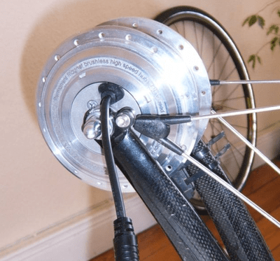
The first fork that we tested was the steel one with lawyer lips from the setup picture above. It's the kind of fork that most people wouldn't think twice about installing one of these hub motors on.
Steel Fork Closeup.jpg

The results show no detectable axle rotation at all up until 50 Nm. After that, it started to give a little and then at 75Nm and 4 degrees was appearing to plateau . But then it got stiffer again and made it up to 95 Nm at about 7 degrees before reaching a true plateau.

Steel Laywer Graph.jpg

There was quite a lot of resistance during continued rotation building up to 100 Nm before it finally started to roll completely out of the dropout at 40 degrees. We thought that something else in the jig might have been slipping at the ~26 degree point which is why the graph goes down and up as we let go of the arm to investigate before resuming once we saw that everything on the jig was fine.

In the end the dropout fully spread open and one of the lawyer lips was speared back as the axle eventually climbed itself right out of the dropout.
Steel Fork Spread.jpg

The next test was on an even older steel fork without lawyer lips. This one here
Steel No Lawyer Closeup.jpg

The spinout behavior was a little different. We saw some motion at 20 Nm which we presume was the axle rotating until the tabs from the anti-rotation washer were fully pressing against the base of the dropouts. After that, it got stiff again right up to 50 Nm, and then started to yield, reaching 90 Nm at just under 10 degrees and a peak of 104 Nm at 20 degrees. As the axle rolled out the torque dropped steadily downwards from here, unlike the fork with laywer lips that stayed up in the 80-100 Nm realm for the first 50 degrees of rotation.

Steel Without Lawyer Graph.jpg

The next test after this was on the aluminum road fork. This had a dropout thickness of 6.4mm, or 1/4". The steel forks meanwhile both measured at 5.2mm.

Aluminum Dropout Closeup.jpg

And how did it fair? The graph tells the picture

Aluminum Fork Graph.jpg

No motion on the axle at all until 45 Nm. Then it starts to give a little bit and at just over 50 Nm the dropouts start spreading open. Unlike the steel forks the resistance doesn't continue to increase to the 100 Nm realm, but maxes out at about 53 Nm for the first 20 degrees and then drops down as the axle rolls out.

Consistent with my previous tests, the aluminum fork dropout didn't break or crack but simply spread open just like the steel forks.

Al Fork Spread.jpg

And here is that same test done as a time plot, so you can really see no motion at all for the first 10 seconds while we increased the force on the lever.
Aluminum Fork Time Graph.jpg

Bafang rates most of these small geared motors as having a max torque in the realm of 30 Nm, and if you were to limit the controller phase current so that the actual motor torque didn't exceed this I'd say you are in reasonable territory even with an aluminum dropout. That would correspond to a phase current limit on the order of 30 amps, plus or minus depending on the winding KV.

But if you are running the motors without a phase current limit and at power levels that are putting 40-50 Nm on the axle, then things are definitely right on the edge.

Next up, the two suspension forks! Anyone wanna take wagers on the failure torque with the magnesium Rock Shocks or the steel Suntour units? Here's a closeup of the dropouts in each case:
Suspension Dropouts.jpg
 
Awesome testing! Having real-life numbers for the fail points is priceless.

Having some way to keep the dropouts from spreading seems like it would be good.
 
fechter said:
Having some way to keep the dropouts from spreading seems like it would be good.

That would be a pretty funny and viable approach for a torque arm strategy for motors with these stabbed washers. There's nowhere to grab on the axle as it's round, so just have some external 'U' plate that just mechanically confines dropouts so that they can't spread apart!

Anyways our reason for doing these tests is to see if we shouldn't fabricate a custom torque arm that replaces the inside tabbed washer, allowing it to extend down and out allowing it to bolt to a more conventional torque arm arm that is hose clamped to the fork. The tests above suggest this would be prudent given the ~50A phase current that exists on the 20A controllers that they get paired with. There's decent margin to failure with steel dropouts, but almost nothing with alloy.
 
Your preliminary test results concur with my experience running a Crystalyte 5305 at 36V/35A in a Surly Karate Monkey fork. Initially, I lightly filed the fork tips until the fit was as conformal as I could make it. It had not been in service very long at all by the time I noticed the fork tips had spread out-- but it never came close to spinning. My observations of Surly chromoly dropouts since then all bear out the conclusion that they use very mild temper, perhaps annealed, and that the dropouts are comparatively easy to bend but become stronger as they're bent.

I took that bike apart shortly after noticing the damage, and my subsequent plan was to try a fork with broader BMX style dropout plates. But as things happened, it was several years before I felt like e-biking again. So I've not had another front motor since then.
 
justin_le said:
....
Anyways our reason for doing these tests is to see if we shouldn't fabricate a custom torque arm that replaces the inside tabbed washer, allowing it to extend down and out allowing it to bolt to a more conventional torque arm arm that is hose clamped to the fork. The tests above suggest this would be prudent given the ~50A phase current that exists on the 20A controllers that they get paired with. There's decent margin to failure with steel dropouts, but almost nothing with alloy.

I went the "replace the tabbed washer with an inside torque arm"direction over 8000 miles ago. My design is crude but highly effective. And when my alloy forks finally cracked my TA's worked great! The cracking was aided by my bike sitting in 39° F weather for 4 hours before I rode home that night.
(Talk about unexpected activity, this link got a bit lively.... :roll: ..... :lol: )
https://endless-sphere.com/forums/viewtopic.php?f=3&t=92978&sid=080317cf59ef2443c8c5e9319b876880

I have such confidence on the design that I placed the broken part of the dropouts back in it's place and tightened the bolt to 55Nm and have been riding around on it ever since. (around 300 miles so far.)

I never finished the second design for replacing the tabbed washers due to expense. The ones I was running worked and I wasn't going to market them, so I didn't bother. I did have 1/2 of it cut out of aluminum as a test fitting piece, but never went any farther then that . This was the direction I was going before I went on to something else. (I never got to the place where I made the slots for the clamps. and other things one would want.)
TA-1 Part.JPG
T-Plate 3.JPG
:D
 
justin_le said:
Next up, the two suspension forks! Anyone wanna take wagers on the failure torque with the magnesium Rock Shocks or the steel Suntour units? Here's a closeup of the dropouts in each case:

The Magnesium fork's dropouts look quite thick... but magnesium is a bit weaker than most aluminum alloys. My guess is this one will actually crack, not just spread open, and it'll happen at ~50 N-m.

Stamped steel. Hmm... probably a generic "Hi-Ten" steel. I'll give it 70 N-m to full failure, but some opening of the dropouts at ~35.

Thank you for doing this work Justin!!!
 
liontail said:
The Magnesium fork's dropouts look quite thick... but magnesium is a bit weaker than most aluminum alloys. My guess is this one will actually crack, not just spread open, and it'll happen at ~50 N-m.

So you are correct on the former part. The fork dropouts are cast magnesium and lack any ductility, which is the same story as cast aluminum suspension fork dropouts.

Magnesium Cracked.jpg

Interestingly, one side broke the back half off the dropout, while the other side broke the leading edge.
Magnesium Cracked Both.jpg

But the total torque that this took surprised us. The first signs of motion happened around 25 Nm, but the dropouts went up to 85 Nm before snapping. Then as we kept rotating it there were additional breaks as the other side cracked open and/or crack propagated through.

Magnesium Time Graph.jpg

The metal thickness at the dropout on these forks was 7.2mm, so not all that much higher than the 6.4mm thickness of the aluminum road fork that spun out just above 50 Nm. It's worth comparing too to the Suntour suspsension fork that I tested back in 2010.
https://endless-sphere.com/forums/viewtopic.php?p=232469#p232469
In that case I was doing just one dropout at a time and got a reading of 40 Nm with loose nuts, and just over 60 Nm with nuts that had been tightened to 60 Nm. We used 30 Nm as our standard axle nut torque in these more recent tests, to be representative of what someone would normally consider "tight" in the context of a bicycle wheel.

Stamped steel. Hmm... probably a generic "Hi-Ten" steel. I'll give it 70 N-m to full failure, but some opening of the dropouts at ~35.

Yeah we weren't so sure what we were going to see on this one. It's the kind of cheap steel suspension fork that has a dropout made from flattened metal tubing rather than some properly forged piece. But the results were surprising. No yield at all until 50 Nm. Then we start seeing it give steadily but it peaks all the way up to over 140 Nm (!). That's 40% higher ultimate failure point than the non suspension forks with properly formed steel dropout plates from this test.

Steel Suspension Result.jpg

The tabbed washer isn't ad thick as the fork dropout, so you can see that the outer layer was bent differently than the inner layers.
Steel Suspension Failed.jpg
Steel Suspension Failed2.jpg

Anyways, hopefully this test result will help to dispel the frequent advice "never install a front motor on suspensions forks". There could be other reasons for that in terms of the bike's handling, but from a dropout strength perspective there is not any relation between the strength of the dropouts and the presence or absence of suspension.
 
So total newb to this one. I've got a standard wind 1000w hub motor. I get upto around 35-35mph with 48v. I tend to max out around 33-35 amps. How much torque does this motor typically deliver? I know nothing will be exact but just a ballpark figure?
 
Philaphlous said:
So total newb to this one. I've got a standard wind 1000w hub motor. I get upto around 35-35mph with 48v. I tend to max out around 33-35 amps. How much torque does this motor typically deliver? I know nothing will be exact but just a ballpark figure?

Play with this:
http://www.ebikes.ca/tools/simulator.html
Blue line is torque. Read the FAQ and the links to the ES threads where additional features are discussed / explained.

You need to differentiate your battery amps from the motor phase current and disassociate power from torque. At 30 mph, 1000 watts of output power is just 25 Nm of torque. So even the weakest cast alloy dropouts could handle transmitting 1000 watts of power at those speeds with no torque arm no problem.

Meanwhile, 1000 watts of actual output power at say 8 mph requires more like 95 Nm of torque. Whether your particular motor and controller are able to produce 95 Nm of torque is another question. That depends on many factors (controller phase current limit, motor KV and winding resistance, hitting the limits of motor magnetics etc). But it's not out of realm for a large direct drive hub motor to have the capability of reaching that torque level for short times with sufficient input power. (see https://endless-sphere.com/forums/viewtopic.php?p=218312#p218312 for instance).

I'm hoping that with all of this empirical spinout torque testing data and the known motor torque outputs form the simulator we can provide the tools and info for people to choose motor / controller setting combos that will ensure a decent margin of axle spinout safety.
 
Thank you Justin for taking the time in sharing your experience and knowledge.

You pretty much hit the nail on the head with the 30mph torque example, the ultimate way of testing your system out is a full throttle start on hill and long incline climb at slow speed if your not yielding at these levels then you have a good enough set up.

Ive fitted the meatiest torque arm I could make for the frame with out being invasive and then looked at the max power handling of that and it's below my motors max capability so I can run hard all day and have no issues.

I just like to add that a stock a2b metro uses a 3mm high chromium stainless torque arm single sided and with the stock 500watt hub there was no deformation what so ever I don't know the mileage but I don't hear of it being a common failure point on these the frame seems to crack on early models but touch wood I've escaped this with a later model frame and I went with 8mm high chromium stainless in total /dual 4mm plates like all my pics show and that I've not shut up about.

But a tap on back to all involved in advancing ebikes in general, we just need those juicy 5.5ah 20700 batts and next gen hubs then ebikes can get lighter or faster and any mixture inbetween as a result of technical evolution.
 
justin_le said:
Philaphlous said:
So total newb to this one. I've got a standard wind 1000w hub motor. I get upto around 35-35mph with 48v. I tend to max out around 33-35 amps. How much torque does this motor typically deliver? I know nothing will be exact but just a ballpark figure?

Play with this:
http://www.ebikes.ca/tools/simulator.html
Blue line is torque. Read the FAQ and the links to the ES threads where additional features are discussed / explained.

You need to differentiate your battery amps from the motor phase current and disassociate power from torque. At 30 mph, 1000 watts of output power is just 25 Nm of torque. So even the weakest cast alloy dropouts could handle transmitting 1000 watts of power at those speeds with no torque arm no problem.

Meanwhile, 1000 watts of actual output power at say 8 mph requires more like 95 Nm of torque. Whether your particular motor and controller are able to produce 95 Nm of torque is another question. That depends on many factors (controller phase current limit, motor KV and winding resistance, hitting the limits of motor magnetics etc). But it's not out of realm for a large direct drive hub motor to have the capability of reaching that torque level for short times with sufficient input power. (see https://endless-sphere.com/forums/viewtopic.php?p=218312#p218312 for instance).

I'm hoping that with all of this empirical spinout torque testing data and the known motor torque outputs form the simulator we can provide the tools and info for people to choose motor / controller setting combos that will ensure a decent margin of axle spinout safety.

Thanks Justin! To clarify, I can pull about 35A from the battery. No idea on the phase amps. I'm also not sure what type of hub motor I have. I got the generic 1000w black hub motor kit. I believe the stator is 30mm wide...I top out around 34-35mph on a full charged 48V battery.
 
Buk___ said:
What do you think to this design for (say) sub 2k hubs?
file.php


See for the description.

I think these are really clever. I might try to make some although not right away. If you beat me to it and actually build them I'd love to know the dimensions, ie how much bend and how much "extra" is needed for the kinked parts to get the right clamping. Also, how do you plan to make the kinks? The rest looks doable with a drill, hacksaw and file although I'm not much of a metal worker.
 
-dg said:
Buk___ said:
What do you think to this design for (say) sub 2k hubs?
file.php


See for the description.
Also, how do you plan to make the kinks?

Whenever I designed anything similar in the past -- a long time since -- the method for forming the bends was either fly-press (1-offs and prototypes) or a brake-press for production.

At home, I probably clamp the plate to the back jaw of my vice, wind the front jaw open so that it was just supporting the edge of the wing by a few millimeters, and then use a cold chisel and hammer to apply a set at the appropriate point.

Alternatively, you could experiment with using the clamping force of the vice with some appropriately placed packing pieces to squeeze the set onto the jaws. It would probably take a few attempts to work out the right amount of packing though.
 
justin_le said:

Justin, Any chance you could post a dimensioned version of this design?

I'd like to try and re-create your physical results in simulation, and the more accurate the model, the more likely I am to get something close.

Thanks, Buk.
 
Buk___ said:
justin_le said:
Justin, Any chance you could post a dimensioned version of this design? I'd like to try and re-create your physical results in simulation, and the more accurate the model, the more likely I am to get something close.
Thanks, Buk.

I am looking forward to tests with a Grin torques arms myself. Maybe using the type of fork that failed earliest.

:D
 
Back
Top