TSDZ2 mid drive with 860C, 850C or SW102 displays only -- Flexible OpenSource firmware (Casainho code only)

Speady said:
stancecoke said:
As far as I remember, the PAS magnets are in the outer ring of the secondary coil
You are right. There are another 20 tiny magnets .
Thanks. It is really important to know the exact value of magnets so the cadence can be measured.
 
Guys, this is how the torque sensor of your motor works and you can see how fast it reacts:

[youtube]1xiMbCerRKw[/youtube]

NOTE: This video is dedicated to stancecoke/hochsitzcola for his hard work on documenting the ebike torque sensors and helping on our OpenSource firmware for Ebike motor controllers.
---

On this video, our firmware running on TSDZ2 motor controller, reads the torque sensor ADC value and send by UART to the PC and were it is shown in the graph.

This was the very first time I was able to understand how the original firmware controls the hardware to read the torque sensor.
 
Today I was able to advance a lot:
- can read hall sensors
- PWM output works
- brake input signal works
- PAS pin 1 and pin 2 inputs works
- wheel speed sensor input works
- torque sensor reading works (coil excitation circuit + ADC reading) -- details: https://opensourceebikefirmware.bitbucket.io/development_tsdz2/About_Tongsheng_TSDZ2_mid_drive_motors--Motor_controller.html
- battery voltage reading

Question: Do you guys know what is the green wire for on the wheel speed sensor cable?? it is the only cable I miss to know his function.

Cables

• wheel speed sensor cable
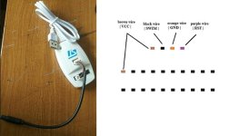
◇ this cable carries the wires for STLinkV2, that is used to program and debug the firmware
◇ this cable carries the wires for the wheel speed sensor
◇ list of the wires and functions:
▪ orange wire | GND | used for: STLinkV2; wheel speed sensor
▪ brown wire | VCC | used for: STLinkV2 (optional); wheel speed sensor
▪ purple wire | RST | used for: STLinkV2
▪ black wire | SWIM | used for: STLinkV2
▪ white wire | wheel speed sensor | used for: wheel speed sensor. This signal is active low, meaning that when magnet is not in front of the sensor, this wire has 5V and with magnet in front, this wire has 0 volts.
▪ green wire | ?? | ??

• LCD cable
◇ this cable carries the wires to power on/off the motor controller and the wires for UART TX and RX that communicate with the LCD
◇ the motor controller can be enabled by simple connect green wire to white wire and this way there is no need to use LCD
◇ list of the wires and functions:
▪ green | P+ | battery voltage!!
▪ black | GND | ground
▪ white | Vin | ground when LCD disabled and P+ (battery voltage) when LCD is enabled
▪ brown | UART TX motor controller |
▪ orange | UART RX motor controller |
▪ purple | brake | this signal is active low, meaning that when brakes are not active, this wire has 5V and brakes active, this wire has 0 volts.
 
eyebyesickle said:
green is 5-6v power for light cable
Thanks.

▪ green wire | 6V for lights | 6V only when display back light is enabled

And found that is STM8S105 PE2 pin that enables/disables that 6V.
 
You probably already know, or don't need this, but just for everyone's reference:

tsdz2stlinkv2pinout.jpg

Green and white from the speed sensor cable are not used, and to make this cable, you can use a speed sensor extension.
 
I saw that the microcontroller works well at least 18V and the mosfet driver should also work. Maybe this motor controller can also work at 24V batteries...
 
My controller don't have throttle connection. Do you know if the cable is different for the throttle version?? Were is connected throttle??
 
Hey, that‘s a really great and fast progress! Seems, that you can take the first ride with the custom firmware tomorrow :D

Regards
stancecoke
 
stancecoke said:
Hey, that‘s a really great and fast progress! Seems, that you can take the first ride with the custom firmware tomorrow :D
Not yet because I will be away from home. But thanks to all the technology, like good mobile PCs, mobile 4G and traveling by train, I am preparing the PWM signals today. Maybe next week I will be ready, If I am careful enough to not burn this controler and mosfets, as this is much hard to repair and I only have 1 unit for now (should receive in 10 days more units).

Fun is that original firmware is setup for 36V battery but I only have 48v battery, so having the firmware is a must to put the controller working with my battery :)

And yes, much more fast than I initially though, but anyway, with all the experience from Kunteng and this is even simple, because has only 16kbytes flash memory and and I am going at about 10kbytes already....
 
Looks like I have some catching up to do! Thank you guys for this thread and all the documentation.

I'll be playing with my own TSDZ2 shortly. Working on getting it all linked up.

Anyone know what the potting compound is in the controllers? Silicone? Just trying to get an idea of what I'm up against in my modding ventures...
 
daytonampco said:
Anyone know what the potting compound is in the controllers? Silicone? Just trying to get an idea of what I'm up against in my modding ventures...
Seems a kind of silicone, it is very soft and easy to remove at small parts...
The only thing I couldn't do was to remove the board from his place. I can remove the screws from the mosfets and the bottom screw but I can move the board from the place because the potting is under the board, I can't remove it... This way I can't for instance repair failed mosfets or even see the board on the under side.
 
casainho said:
My controller don't have throttle connection. Do you know if the cable is different for the throttle version?? Were is connected throttle??

for the 8 pin controller (note colors are different from 6 pin controller) :

Throttle:

ORANGE (THR)
BLACK (GND)
WHITE (5V)

E-brake:

GREEN (BRK)
BLACK (GND)

Note also, the colors are sometimes different for different 8 pin controllers even - let me know if you want me to post an overhead pic of the controller, and mark the ports.
 
eyebyesickle said:
casainho said:
My controller don't have throttle connection. Do you know if the cable is different for the throttle version?? Were is connected throttle??

for the 8 pin controller (note colors are different from 6 pin controller) :

Throttle:

ORANGE (THR)
BLACK (GND)
WHITE (5V)

E-brake:

GREEN (BRK)
BLACK (GND)
Thanks!!
My controller don't has throttle connection but the brakes connection is wired and I read the signal on my firmware.
Maybe for the 6 pins controllers don't has wire for throttle but for the ones who want, will be able to solder the wire to the board and it will work, let's see if the hardware is there.
 
For the record-

8 pin Controller:
black: | GND | ground
blue: | P+ | battery voltage
red: | Vin | ground when LCD disabled and P+ (battery voltage) when LCD is enabled
green: | brake | wired with black ground for 2 pin e-brake/switch
purple: | UART TX motor controller |
yellow: | UART RX motor controller |
white:| 5v | wired with black ground wire and orange throttle wire for 3 pin throttle
orange: | throttle | wired with white 5v wire and black ground wire for 3 pin throttle
 
eyebyesickle said:
For the record-

8 pin Controller:
black: | GND | ground
blue: | P+ | battery voltage
red: | Vin | ground when LCD disabled and P+ (battery voltage) when LCD is enabled
green: | brake | wired with black ground for 2 pin e-brake/switch
purple: | UART TX motor controller |
yellow: | UART RX motor controller |
white:| 5v | wired with black ground wire and orange throttle wire for 3 pin throttle
orange: | throttle | wired with white 5v wire and black ground wire for 3 pin throttle
Great!!
Would be possible for you to identify on the 2 types controller boards were throttle wire connects?? I guess it will be to some header...

It is really important to me to use throttle for testing the motor, which will happen soon. I would like to use the same STM8 ADC pin and that would mean the code would be ready for 8 pin controllers.
 
casainho said:
eyebyesickle said:
casainho said:
My controller don't have throttle connection. Do you know if the cable is different for the throttle version?? Were is connected throttle??

for the 8 pin controller (note colors are different from 6 pin controller) :

Throttle:

ORANGE (THR)
BLACK (GND)
WHITE (5V)

E-brake:

GREEN (BRK)
BLACK (GND)
Thanks!!
My controller don't has throttle connection but the brakes connection is wired and I read the signal on my firmware.
Maybe for the 6 pins controllers don't has wire for throttle but for the ones who want, will be able to solder the wire to the board and it will work, let's see if the hardware is there.

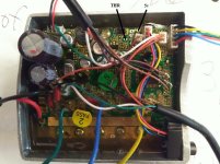
6pinthrottleportsmarked.jpg
 
Thanks!!!

Next I need to put motor working and then I will try to see if the shunt voltage is received by the STM8. I see the shunt on the board but I don't see any opamp... Or can it be on the back side of the board??

I wounder if is possible to measure the battery current and motor phase current as is possible on Kunteng controllers from the shunt.
 
Thanks eyebyesickle. I confirm that I have throttle now :)
 
I have found that if you need to remove a pcb from an encapsulated enclosure, it can generally be removed successfully, by tapping each existing PCB hole with a screw thread (a size larger than the existing screw), wherever a (screw) hole already exists in the PCB and any existing screw can be removed.

I don't know if this holds true for the TSDZ2 controller, but it generally works without damaging anything, if all available holes are used and each screw has a similar amount of torque applied. The PCB is pushed out by the force between the screw, the PCB and the enclosure. Ideally the encapsulant and PCB come out together, but sometimes the encapsulant will separate from the PCB (occasionally causing a weak component or joint to fail). If there are lots of mounting holes (and there doesn't appear to be on the TSDZ2 controller) it can sometimes be OK not to need to tap threads into all the semiconductor mounting holes, but it is generally better to remove the existing screws if possible.

If there are no holes in the PCB or very few/small holes, it is often easier to drill a small hole through the PCB (stopping short of the enclosure) or through the enclosure (stopping short of the PCB) and use compressed air to force the PCB and encapsulant out, in fact I often try this before resorting to tapping all the holes.

This even works on epoxy/urethane encapsulates, where the surface of the (alloy/steel) has a smooth finish, but the finish doesn't matter so much for softer encapsulates like silicone or TCR. Heat helps soften and weaken hard encapsulates, most circuits can survive 120°C, few encapsulants stay hard at that temperature, but wear safety glasses, gloves etc, hot burns quickly!

Anyway, I am very pleased to see the progress on the firmware, I didn't think I'd be able to contribute to the project as I don't currently have a TSDZ2, nor great programming skills, but hopefully this could help identify where the current sensing goes.
 
ThousandWax said:
Anyway, I am very pleased to see the progress on the firmware, I didn't think I'd be able to contribute to the project as I don't currently have a TSDZ2, nor great programming skills, but hopefully this could help identify where the current sensing goes.
Thanks for sharing. I hope later to try remove the board.
 
Guys, this is your motor running with our OpenSource firmware! I was using a throttle on that test.
So, since the other last video, seems that what is missing right now is "connecting" the torque sensor signal to the motor "throttle" signal, right?? Not yet, first I need to be able to read motor current and limit it to the max recommended value to this controller or the mosfets will burn :)

What I did learn that may be important for you:
- the controller can run with a battery pack from 7S (24V) up to 14S (52V)
- seems that all controller versions have the same hardware but for instance, brakes and throttle wires are missing. Don't know about the original firmware but our firmware should support all options (so, every controller version will work with or without brakes and throttle)

The test I did:
At 36V battery voltage, the measured time on hall sensors for 1 ERP was 1.94ms.
Motor has 8 poles, so the measured speed in RPMs = 60 / (0.00194 * 8) = 3866 RPMs.

Voltage
• Controller can run the motor from 20V battery input up to at least 60V (this values were tested)
◇ 20V will work for a 7S battery (min voltage per cell = 2.86V)
◇ 60V will work for a 14S battery
◇ controller capacitors on input voltage line are rated at 63V

[youtube]O9shbfQ9hHk[/youtube]
 
Measuring battery current
STM8 pin PB5/AIN5 measures the analog signal for the battery current and for each 1 amp, the signal increases 0.275 volts. The max current measured is: 5V / 0.275V = 18.18 amps. Assuming the signal can be linear and I did my measurements correct, maybe the measured current can't be more than 18 amps.

I don't think there is any other current measurement. Or maybe there is, but can be a digital signal that I can't trigger with my tests... really need to see the board from the back side. Or disassembly the original firmware...
 
casainho said:
Guys, this is your motor running with our OpenSource firmware! I was using a throttle on that test.
So, since the other last video, seems that what is missing right now is "connecting" the torque sensor signal to the motor "throttle" signal, right?? Not yet, first I need to be able to read motor current and limit it to the max recommended value to this controller or the mosfets will burn :)

What I did learn that may be important for you:
- the controller can run with a battery pack from 7S (24V) up to 14S (52V)
- seems that all controller versions have the same hardware but for instance, brakes and throttle wires are missing. Don't know about the original firmware but our firmware should support all options (so, every controller version will work with or without brakes and throttle)

The test I did:
At 36V battery voltage, the measured time on hall sensors for 1 ERP was 1.94ms.
Motor has 8 poles, so the measured speed in RPMs = 60 / (0.00194 * 8) = 3866 RPMs.

Voltage
• Controller can run the motor from 20V battery input up to at least 60V (this values were tested)
◇ 20V will work for a 7S battery (min voltage per cell = 2.86V)
◇ 60V will work for a 14S battery
◇ controller capacitors on input voltage line are rated at 63V

[youtube]O9shbfQ9hHk[/youtube]
That's awesome progress / findings! Thanks for keeping us up to date, this is truly exciting!!!
 
One of the biggest disappointments of the standard motor is not being able to handle 14S batteries ( the difference between 13S and 14S is night and day on my Bafung which just seems to put the motor into a real sweet spot of power to efficency ) , I would accept a lower current max in lieu quite happily as at 18amps that's over 900W which is way more than you really need for a mid mounted motor on single track trails.
 
Back
Top