My Sun Trip Bike, Back to Back Tandem Trike with Rowing Generator, Pedals, +Solar

Most MPPT controllers are made for stationary panels and have a really slow response to changes. This might be a problem for a moving bike. Maybe there's a way to speed up the response? If the panels are just run to the pack directly it will probably be rare they need to be disconnected due to full charge. But you would still want some kind of charge cutoff when the pack voltage gets high.

The person riding in the rear can have the job of tracking the panels.
 
Question? If you want a rowing bike? Wouldn't it be easier, simpler, cheaper, and faster to just buy a rowing bike? Lot of rowing bikes here:
https://rowingbike.com/en/

Question number 2? For a normal human, what is the most efficient bicycle design? Pedal or rowing? I want to transport my self 10 miles as fast as possible, using as little energy as possible. Should I buy a pedal or rowing bike? No hills but lots of wind.
 
Guillaume,
Great Work there , something I have been wanting to do for years myself.

When designing and offering for sale your charge system, Note : Many of us are now using 52 volt / 14s battery packs.
so the charge controller would have to go up to 59.x volts / just under 60 volts .

shipping cost from you to other places in the world ?


GUI13 said:
 
justin_le said:
Oh sweet work! We were going to have a manual adjustment for the tilt of our roof canopy with telescoping support tubes and just tweak it now and then, when the sun is obviously more to one side of the other. But watching that automatically tilt back and forth as you corner around is pretty magical. Time to replace the telescoping support tubes with linear actuators now :)

Seriously Guillaume, that's nice work. I presume by you saying this is GPS control that you are using open loop angle computations based on your heading direction and position + time of day? Or is there a closed loop control based on optical sensors to sense the direction of shading and or the solar power levels?

find ! :D
the right angle is calculated based on GPS data , at low speed and at stop we use a current sensor on PV to have the best exposure
we have too a manual position ( panel flat ) for windy day or trafic jam
 
marty said:
Question number 2? For a normal human, what is the most efficient bicycle design? Pedal or rowing? I want to transport my self 10 miles as fast as possible, using as little energy as possible. Should I buy a pedal or rowing bike? No hills but lots of wind.

Pedaling is more efficient. On a flat road, a velomobile is the fastest way to cover 10 miles on human power only.
 
marty said:
Question? If you want a rowing bike? Wouldn't it be easier, simpler, cheaper, and faster to just buy a rowing bike? Lot of rowing bikes here:
https://rowingbike.com/en/

Sure, and here's one that's already been electrified
https://endless-sphere.com/forums/viewtopic.php?p=1362573#p1362573
Oh wait look, it's sitting in my shop downstairs ! :wink:

One fun aspect of this project is that I need to link up both a rowing system and a pedaling system to the same tandem drivetrain. If you look at cutting up and hacking an off-the-shelf rowing bike to attach to the back end of my tandem trike (which is I presume what you were suggesting here?) then it's generally going to be less elegant than doing that section custom to this vehicle geometry.

I want to transport my self 10 miles as fast as possible, using as little energy as possible. Should I buy a pedal or rowing bike? No hills but lots of wind.

Whether you are pedaling or rowing is almost inconsequential to that goal, all that really matters there is the aerodynamics of the vehicle. I'm hands down faster rowing on the THYS rowingbike than pedaling my upright bike, and I'm passing cyclist all the time when commuting on it in Vancouver without assist. That's not because the rowing is more efficient at harnessing human power than pedaling, it's just because the THYS rowingbike is recumbent and has a smaller aeorodyanmic footprint.

I've talked at length on this topic with Colin Angus who's been involved in many records and races for distance travelling n a rowboat (https://angusadventures.com/expedition/world/ , https://angusadventures.com/expedition/race-to-alaska/ etc.). Many of those have been neck to neck with someone on a pedal powered boat. He's pretty much of the conclusion that you can get slightly better sustained power output from pedaling than rowing, but not much.

If you go back to my original posts in this thread, the motivation for having a rowing option is to mix up the exercize so we're not just sitting there spinning legs all day, rather than any specific efficiency goal.
 
Wow, this is a wild coincidence! I just saw a tandem recumbent for the first time in my life this past weekend. I didn't even know they existed before that. Now I see Justin building this... crazy world we live in.

This build (and the upcoming tour) sounds so cool. It pretty much incorporates everything I find awesome. I'm definitely going to closely follow this thread.
 
justin_le said:
it's just because the THYS rowingbike is recumbent and has a smaller aeorodyanmic footprint.


If you go back to my original posts in this thread, the motivation for having a rowing option is to mix up the exercize so we're not just sitting there spinning legs all day, rather than any specific efficiency goal.

Yes. I was faster on my Thys than I ever was on an upright. The Thys is basically a laidback, high bottom bracket recumbent, without a bottom bracket. :)

For endurance, I did find that rowing was easier for all day riding. You spread the work out over a lot more muscles.
 
justin_le said:
Yeah, since it's a rooftop canopy I can't see any advantage to doing anything other than a perfectly flat panel with all the cells on exactly the same plane and getting the same incident light. Curved panels arguably look better, but in this case make little sense.
That makes things a lot easier (similar insolation/temps on all cells.) For those cases long strings work out well. Will you be able to get long enough strings to provide you with the charge voltage you want? For a 36 volt system you'd need at least 85 cells in series at 25C (more at higher temps.)
Yeah hopefully not too many colder temps on this particular trip. That's an interesting point about the MPPT tracking getting thrown off by local maxima from having differently oriented cells. If I do run with a solar charge controller I'll hook things up in a way to ensure that the panel strings can be easily re-configured for adequate voltage into the pack without a controller if need be. I have full confidence in the BMS board to do overcharge protection with this particular pack setup.
Please be careful. One of the main reasons li-ion batteries are relatively safe nowadays is that they have at least two levels of overvoltage protection - one provided by the charger, one provided by the BMS. Going to a single level of protection (and relying on it to terminate charge) increases the odds that a single failure will result in a fire.

Also keep in mind that you won't get full charges in those cases. If you rely on voltage termination you will hit the trip voltage (~4.3 volts per cell) before the pack is fully charged. The loss of capacity will depend on the charge rate; at a 1C rate you'll see a significant loss of capacity, with lower rates giving you closer to a full charge.

What is the format of the race? Is solar used only during actual racing? In that case termination behavior doesn't matter as much, since you will almost always be charging a less-than-full pack. Will they be used for charging before/after racing hours? If so charge termination behavior becomes more important.
 
justin_le said:
But when we used weight lifting gloves that only covered the palms and were held in place with a thin strap, it made a huge difference.

Great idea.

I'm going to start posting sketches of the rowing mechanism I have in mind next. But basically, the idea is that the legs will be pushing on the pulley portion of a pulley system, while the arms will have the end of the rope, and that means that the leg force will be 2x the arm force while rowing, like they each have their own gear ratio. And I'm hoping that this leads to a better overall balance in the leg vs arm load distribution during the stroke.

I missed this before. You are absolutely on the right track! My favorite rowing shell used this setup.

https://web.archive.org/web/20050129182908/http://forwardface.com:80/
 
Most of that link is gone or busted. :-(

https://web.archive.org/web/20040719064809fw_/http://forwardface.com:80/regatta98/zrower98_01.jpg
https://web.archive.org/web/20040719065610fw_/http://forwardface.com:80/regatta98/zrower98_02.jpg
https://web.archive.org/web/20040719070757fw_/http://forwardface.com:80/regatta98/zrower98_03.jpg

https://engineering.dartmouth.edu/magazine/inventions-forward-facing-rowboat

http://archive.boston.com/news/globe/obituaries/articles/2007/11/08/warren_loomis_67_started_three_companies/

His design was brilliant. The cable ran back to a compact stern drive with a cable drum, and a big two blade model airplane appearing prop, perhaps 18" in diameter. I don't recall if it was completely submerged or surface piercing.
 
fechter said:
Most MPPT controllers are made for stationary panels and have a really slow response to changes. This might be a problem for a moving bike. Maybe there's a way to speed up the response?
You generally don't have to. The MPPT controller does most of its work when the temperature changes; that changes the voltage of the array and thus changes the PWM duty cycle the MPPT needs to run at. Insolation changes (i.e. you turn a corner and the array goes from south facing to west facing) don't require much of a PWM change, since voltage in to voltage out ratio remains the same. Current changes of course, but the buck converter within the MPPT doesn't need to "track" that.
 
The varying load (due to the motor and driving conditions) and varying cosine angle to the sun of a solar panel array on an ebike is not consistent with the assumptions normally made when designing an MPPT controller. Of course the details depend on the algorithms chosen and the feedback parameters used, but it could be a rather suboptimal solution to the problem in the worst case.
 
Cowardlyduck said:
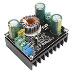
I've had reasonable success with a this cheap DC-DC converter on my setup. . . . .It might not be the 'most' efficient, but certainly gets the job done at a reasonable cost, size and weight.
They can work, however:

1) You need an additional circuit to prevent input voltage collapse, which happens with DC/DC converters when impedances are not matched.

2) You need yet another circuit to keep the array close to its max power point. This can be as simple as a knob (i.e. manual MPPT tracking) or as complex as a processor that does sweeps (i.e. runs an MPPT algorithm.)
 
You know what would be awesome, and maybe since Justin is doing this project it might be possible. If the Cycle Analyst could act as a charge controller.
i.e. a plugin unit to the CA that would do the charging (since the CA hardware can't handle much current) that would connect via the CA serial port and feed the CA charging info. Maybe the CA could even control the charger in such a way as to make it an MPPT.

Is this even remotely possible Justin?

Cheers
 
tigcross said:
Hey Justin, great to see the progress. Are you going to use a geared hub motor or DD hub motor for your generator? Have you tried out a gearmotor yet for that purpose?

Hey Tig, excellent line of questioning. It's possible to use our Trip Simulator web app tool to perform a simulation set to see exactly how efficient a hub motor will be as a generator at any given power output and RPM. In my situation, I figure I can average 150 watts reasonably well on a rowing platform, but that is alternating power strokes and recovery strokes of like 300 watts then 0 watts.

In order to use the tool, create a straight line downhill elevation plot, check the "regen enabled" checkbox for the controller parameters, set a vehicle speed limit, and then play around with either the vehicle mass or the %grade until the "Motor Power" field on the right shows exactly the amount of mechanical energy you want to put in the motor. In my case here, I've set that up for -300 watts.

You can see in the "show advanced" column on the right that this hub I've chosen (the SAW20 motor) will produce power with just over 83% efficiency. 300 watts of mechanical power going into the motor, and 248 watts flowing back into the battery.
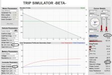
Trip Sim for 300 Watts.jpg

In this particular simulation, I've set the speed limit to 30kph and used a 16" wheel diameter so it corresponds to the motor spinning at 391 rpm. If I wanted to know the generating effiency with 300 watts going into the hub but it only spinning at 200 rpm, we just change the wheel diameter from 16" to 31.3", and now the 30 kph downhill speed limit corresponds to a 200 rpm hub. Doing that we see that the efficiency drops to a miserable 53%, and I have a full 130 watts of copper loss in the motor. The 391 rpm / 16" wheel test had just 26 watts of copper loss.
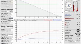
Trip Sim for 300 Watts, 200 rpm.jpg

And here's where things get more fun and interesting. At the bottom left of the page is a button to launch a simulation set. This lets you have any one parameter cycle through a range of values, with the data output from the trip simulator saved into a .csv file that you can then analyze in a spreadsheet.
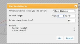
Simulation Set.jpg

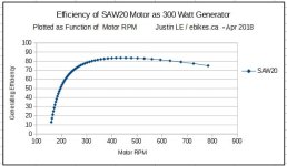
In my case, what I want is to find the RPM at which this SAW20 motor will have a maximum regen efficiency with 300 watts of input power. At low RPM's the core losses are low but copper losses are quite high, while at fast RPM's you can have very little copper loss as the phase current for a given power is much lower, but the hysteresis and eddie losses in the core can grow to become substantial.

By varying the wheel diameter from 8" to 40" while the vehicle speed stays fixed at 30 kph, I'm effectively running simulations from 150 rpm up to nearly 800 rpm.

Here's that plot of efficiency vs RPM for that SAW20 motor
SAW20 Eff Plot.jpg

We can see that with this motor it would be ideal to gear things so that it will spin at about 475 rpm during the stroke, which will do 83.6% efficiency.

Meanwhile, the exact same test with the larger Crystalyte H3540 motor shows a similar peak of ~84% efficiency, but at just 250 rpm. The SAW20 motor makes most sense since it has the same efficiency yet is smaller and lighter. But if the linkage is such that you can only spin the motor at 200 rpm, you'll be better off with the H series motor.
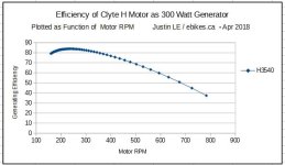
H3540 Eff Plot.jpg

You asked about small geared motors as generators, and here's that the Bafang G01 looks like:
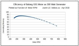
G01 Eff Plot.jpg

Not bad at all, better than both direct drive motors so far with a peak over 85% efficiency at 265 rpm

I did this analysis with a range of different motors while exploring which would be the best option to use as a generator for this rowing bike (300 watt power bursts) and here's how they all stack up.
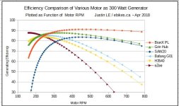
Efficiency Plots Compared.jpg

The best for sure is the BionX PL350 motor, over 90% efficient over the very broad range of 350 - 600 rpm. The reason that it fares so well is that the core losses are quite low on this motor compared to comparable size direct drive hubs.

Next up would be the geared eZee motor or the direct drive Grin All Axle hub motor. Both of these can do around 88% regenerating efficiency and both motors weight just under 4kg. However, the eZee motor would have to be spun at a very low 150 rpm, while the Grin motor would need to more like 350 rpm. So the appropriate motor choice in that case would depend if there is an advantage in the gear transmission to having the motor spinning faster or slower.

You can use this same Method TIG to see how any of the motors we have (geared or DD) would fare as a generator in your electrom machine. In that case I would set the power to 150-200 watts rather than 300 watts. The power setpoint of course has a huge effect on the results.
 
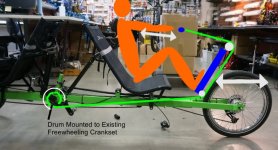
In my initial scheming for this there was no doubt that it would make most sense to do the rowing station as a generator just because it would save what could be a complicated mechanical linkage challenge to mate the rowing and pedaling drives together. However, one thing that I didn't count on was finding a platform frame that had a freewheeling crankset already linked up as part of the original tandem pedal station in exactly the right location for a simple mechanical drum linkage.

So based on that, this is the current working design plan for the rowing section. Green line would be a thin rope.

Rowing Drive Idea.jpg

In this design, the legs are effectively pushing a pulley rather the rope directly, so they will see twice the force as the arms. And each 1" of travel pushing with the legs is equivalent to 2" of pull from the arms. This is different than most other rowing system that I've seen, but I think it will result in a better balance of the overal leg and arm contributions.

That freewheeling crankset makes it so tempting to scrap the generator idea and just machine a special drum that replaces the left stoker crankset. A string would wrap and unwrap this drum, and when the rower is pulling it puts a torque on the drum no different than a legs spinning the original crankset. No generator in this case, probably the smarter approach at this stage.
 
You could make the foot pegs for the rowing mechanism movable to adjust the mechanical advantage.
 
justin_le said:
In this design, the legs are effectively pushing a pulley rather the rope directly, so they will see twice the force as the arms. And each 1" of travel pushing with the legs is equivalent to 2" of pull from the arms.

I think you are missing something here. Pushing a pulley will pull twice as much rope, if the rope wraps around the pulley 180 degrees, as in the case of a pulley out ahead of you on a linear slide. However, you have a pulley on a pendulum. The cable running from the pulley at the fulcrum to the pulley at your feet will not be pulled during the stroke...only the cable from the feet back will be pulled. So you have a 1:1 setup arms-to-feet.

As a side note, this design goes back to an 1890's rowing machine patent.
 
fechter said:
You could make the foot pegs for the rowing mechanism movable to adjust the mechanical advantage.

Yes. If the foot pegs were half way up the pendulum Justin would get the 2:1 ratio he is looking for. But the shorter the pendulum for the feet, the less you approximate a linear path.
 
Back
Top