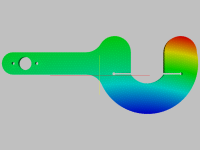
The ultimate torque arm (For <2kW and standard axles)?

amberwolf said:
In my case, neither controller responds to any form of braking control other than on/off. :( Unfortunately most controllers are like that, and only some (though a growing number) can do proportional braking, where there is some method for a degree of control over how much braking force is applied.

Understood. You might find this interesting.


amberwolf said:
It does look a bit complex to manufacture;

Agreed, but the principle -- two pieces that gets around the moulded-on plug problem -- that fit together; and using wedges, that cause the action of tightening of the nut, to clamp the assembly tight to axle flats, can be simplified.

The next iteration of the design combines the physical attributes of both parts into one reversible part.

That not only reduces the production cost by only needing to produce on part in stead of two, it turns out that it simplifies the machining required and reduces the combined material costs.

amberwolf said:
are each of the two parts in the diagram intended to be made from one piece of metal each, and then just the arm made of the spring layers?
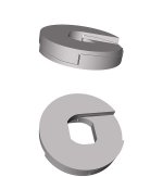
Correct. By moving the shock absorber further away from the center of rotation, it reduces the forces it needs to deal with, reducing the required spring rate, and or allowing the same material to handle higher loads.

Still two parts rather than one, but most TAs are two part affairs (at least) anyway.

It'll be a while before I get to that.
 
fechter said:
Anytime somebody starts bragging about how great they are, it's a red flag.

I'm not "bragging", just stating what I know to be true.

Should I back down and pretend I'm wrong when people denigrate what I've written -- and along the way, contradict established engineering practices, material science and physics -- just to avoid looking boastful in your eyes?

In this thread, and others, I've bent over backward explaining, citing references, producing drawings and analogies to explain what I know -- not think, hope, guess or believe -- but know, and can prove -- to any engineer's satisfaction -- to be simply facts.

Facts I've acquired through a combination of education, and practical experience, over a lifetime of work.

When people continue to contradict those facts on the basis of nothing more than their own, self-vaunted, opinions; sure I start to get a little strident in my expression of those facts. (Who wouldn't?)

Update: You know your name, address and birthday. If you stated those here and I contradicted you, you would probably be quite strident in your defense of those known-to-you facts.

For me, the facts I stated that are being contradicted in this thread are as well-known to me as your name etc. are to you. Of course I'm going to get shitty with people contradicting them on the basis of their opinion alone, with no supporting evidence whatsoever.

fechter said:
What the members here have is a lot of practical experience, which I consider to be more important than math skills.

I have nearly 45 years of "practical experience" in engineering and engineering design; that goes way beyond buying a bunch of bits and doing some nuts up.

Not so much of e-bikes, but engineering principles -- and the math and physics that underlie them -- are just as applicable to those and they are to the cars, planes, boats, and other structures I do have experience with. They do not change.

I hate that just doing what I know, seems boastful to you, but if other people stuck to what they know, and would take the time to look up what they do not, ...

Eg. When I was looking to buy a tyre to fit to my newly built hub, I was all but ready to but a Marathon Plus, which a lot of people swear by, when I read a post here by Chalo recommending a Panracer RibMo PT.

His recommendation for that, and against MP+, made me think again. I had already seen some criticisms against the MP+ around the web, and they tallied with Chalo's comment and so I bought the RibMo essentially on the strength of his recommendation, despite that a source was difficult to locate. And I haven't regretted it. It's early days in terms of mileage, but it seems to be wearing very well and I haven't experienced any slipping or sliding despite wet and frost. (The same cannot be said for the front tyre my bike came fitted with, which I will change before the autumn. It'll be all but worn out by then anyway.)

On the subject of buying parts for bikes that balance reasonable quality and fitness for purpose with a reasonable price, I recognise Chalo's knowledge as not just vastly superior to my own, but superior to many other people's opinions, not just for his depth of experience, but also because he isn't driven by fashion or the need to buy the top of the range Shimano or exclusively (priced) designer goods, in order to demonstrate that he rides a bike by choice, not because he cannot afford a car, as so many are.

But his opinions on engineering ... not so much.
 
I apologize for being bitchy and helping to derail this topic. Just some of your posts could be taken as personal attacks on other members, which is not allowed and doesn't help anything. It sounds like "I'm right and you're wrong because I have 40 years of experience", which is not a valid argument. Highly skilled and experienced engineers screw up all the time. That's why rockets explode. I only have 39 years of experience as an engineer and 9 issued US patents but I am always interested in peoples' real world experience. I've noticed that most people I know with good engineering skills tend to be lacking in social skills and vice-versa. I am an example.

The purpose of this forum is to promote the exchange of technical information and innovation in the area of personal electric transport. We should try to focus on the technical issues and avoid getting into personal insults.

Back to the original topic, I am very interested in seeing an improved solution to the torque arm problem, as most solutions still have serious weaknesses. I have dual torque arms on my A2B that are the typical double D shaped hole in a metal plate. Last time I took the wheel of for service, I could see where the axle was hammering against the plate and had made dents in it. This is with axle nuts tightened to 60 ft-lbs. Something that takes up the slop in the connection and prevents any movement would be good. It also needs to be relatively easy to take apart for service.
 
fechter said:
Just some of your posts could be taken as personal attacks on other members, which is not allowed and doesn't help anything.

Hm. Alan B claimed I'd enacted a "personal attack" on him, I assume that is what you are referring to.

I looked back at what I wrote, other than questioning his expressed technical opinion, and his lack of any supporting argument -- which I assume is okay -- the only thing I can think he/you could be upset about, is my saying he is "not an engineer"; because no engineer would present an argument in the manner he does.

If I said to my doctor, dentist, accountant, or lawyer, "you are not an engineer", they would not be insulted. Nor would a chef, a mechanic, a publican or a shopkeeper. It's just a statement of fact.

And if I wanted to insult someone I knew to be a fellow engineer, then I'd be more likely to say something like: You are not much of an engineer.

But no engineer would present their opinion citing only "they'd assembled 3 e-bikes and ridden them for ten years", as an argument. They'd have the skills to cite appropriate references; as I have done continually.

fechter said:
It sounds like "I'm right and you're wrong because I have 40 years or experience", which is not a valid argument.

This is typical of the misreading and misattribution here. The only time I've mentioned my past experience is in the post to which you are replying, and as a direct response to your statement that "What the members here have is a lot of practical experience, which I consider to be more important than math skills.".

Ie. A direct refutation of your implication that I had no "practical experience".

Not "an argument", just another statement of fact.

fechter said:
Highly skilled and experienced engineers screw up all the time. That's why rockets explode.

Why rockets explode is, because the engineers either failed to do enough analysis, or failed to take the time to re-design and re-analyse when earlier analysis raised question marks. The O-rings were a known problem that was not dealt with because the engineers legitimate concerns were ignored for political reasons.

In part,that why I eshew the frequent calls to build it and test it to destruction. I would never manufacture and fit anything to my bike that I wasn't very convince was safe; nor would any engineer.

And I do not have the resources to destruction test something on the bench for the sake of it. Besides which, it would prove nothing without having first proved the test performed was a valid representation of the in-service stresses and strains; and purchased measuring equipment sufficiently accurate to make a destructive test yield valid data.

Besides which, torque arms -- nor anything else on an ebike -- do not require "rocket science"; all the mostly extremely simple math involved, was solved by Victorian engineers or earlier.

Hooke's law, pretty much all you need to know to analyse my design, was formulated as far back as 1660; a hundred years before the US became the US.

fechter said:
I only have 39 years of experience as an engineer and 9 issued US patents but I am always interested in peoples' real world experience.

I wasn't trying to start a pissing contest -- just defending against your charge that I had none -- besides which "no of patents" is a pretty poor card to play in engineer's top trumps.

Do you know how many patents there are on the books for over-unity machines and other such bunkem? I'm not questioning the validity of yours, only saying that a bare count alone doesn't mean very much.

I'm simply asking that if people think something I've said is wrong, don't tell me I'm wrong, show me. That's the point of peer review.

Don't just state your opinion, show me the basis for it. Show me where my math is wrong; or how I am misinterpreting Hooke's Law.

Something, anything that shows me that your opinion is based on more than guesswork and assumption.

I'm bored, fed up and disappointed that despite the exceptional (possibly unique) efforts I put into trying to explain the basis of the design, to get only uncorroborated opinion in return. Most of which is -- to an engineer -- so obviously wrong, that it borders on the ludicrous.

I think I'm done here. Perhaps I just had too high expectations of this place.
 
amberwolf said:
It does look a bit complex to manufacture; are each of the two parts in the diagram intended to be made from one piece of metal each, and then just the arm made of the spring layers?

Latest version is much simpler; with one reversible part providing both halves of the clamping action.

(The rendering is not great.I'm having to get to grips with a different 3D CAD, because the one I've been using doesn't produce files that the on-line FEA will work with.)

I think this shows how the two identical halves, fit around the axle and the ramped internal surfaces clamp onto the axle flats as the nut is done up to eliminate freeplay and adapt to different tolerances?


AWTA2-3d.jpg

I've still got nothing on the spring part, but I guess the design would work worth a solid arm if you are unconvinced by the benefits of that. It could even be adapted to Justin's behind the chainstay design.
 
Not so thrilled of that unusual design above,.... mostly due to cost and precision of manufacturing for markets. BUT, it may have a place in some unique applications. And I suppose that's what I like most of that original "multi-layered" design,... it's not much different than typical TAs for general use, AND has some versatility for BROADER general use.

I noted that I'm running a 1500w hub in aluminum frame dropouts WITHOUT torque arms. This is a large, thick, heavy "plate" sort of dropout, that causes me little concern (although regularly and closely inspected), unlike those dropouts of thin plate, small surface area, light-weight designs, or of cast alloy, which have proven by others experience to be very poor and even dangerous for such purposes beyond that of normal bicycle use, with or without torque arms. Still,... I'd feel more confident with jus a bit of added steel if only on one side of my dropouts. My lack of torque arms is due to the thick aluminum plate on both sides that leaves no room for typical general purpose TAs of nominal thickness, nor any others currently marketed. Barely have room for minimal required washers and such. The "multi-leaf" design would provide the flexibility "I" require in my needs, by using all that I can, even if only a few, in providing a margin of protection above none at all! I also feel that the design provides an added "locking" benefit that would conservatively replace the basic required lock-washers and serve multiple purposes in replacing those with an added "leaf" of torque "arrest" AND locking protection. Given it's simplicity, materials, and unique design qualities, I'd expect to find it economically available (or easily fabricated myself) AND a very viable AND RELIABLE alternative to consider for my purposes,.... that being under 2000w.

I'll not lay claims to my life-long mechanical engineering experience since the late 60's,... but unlike many young engineers today, at least I know what a screwdriver is and how to use it! :roll: It's a long proven essential tool of rugged simplicity,.... and rugged simplicity is often lacking in many modern designs, screwdrivers included!
 
The two-piece design would benefit from the laminar construction of the open-sided design. That would make it cheaper to manufacture and feasible to have a full thickness interface at the axle (and a continuous clamping surface). It would require spot welding or perhaps riveting to permanently align the layers into stacks without fouling the axle nut.
 
DRMousseau said:
The "multi-leaf" design would provide the flexibility "I" require in my needs, by using all that I can, even if only a few, in providing a margin of protection above none at all! I also feel that the design provides an added "locking" benefit that would conservatively replace the basic required lock-washers and serve multiple purposes in replacing those with an added "leaf" of torque "arrest" AND locking protection. Given it's simplicity, materials, and unique design qualities, I'd expect to find it economically available (or easily fabricated myself) AND a very viable AND RELIABLE alternative to consider for my purposes,.... that being under 2000w.

The exact intended target. And thank you for speaking up.

As soon as I have got to grips with this new 3D cad enough to be able to reproduce the design in it, I should be able to run the FEA and get some accurate numbers for the stresses and strains -- which so far have only been sized using ball-park integrations -- and I'll be able to adjust the material specs spring rate accordingly.

I'll should also be able to come up with numbers for the torque levels that different numbers of layers can handle. When I do, I'll post that data.
 
Buk___ said:
Latest version is much simpler; with one reversible part providing both halves of the clamping action.

I think this shows how the two identical halves, fit around the axle and the ramped internal surfaces clamp onto the axle flats as the nut is done up to eliminate freeplay and adapt to different tolerances?
AWTA2-3d.jpg

I've still got nothing on the spring part, but I guess the design would work worth a solid arm if you are unconvinced by the benefits of that. It could even be adapted to Justin's behind the chainstay design.

It looks simpler, Im still imagining how it might be manufactured in a way I could do here, but I think I *might* be able to by hand, though ti would require fitting and filing till they matched each other. Not a mass production method, but something I could at least test on one wheel, and see if it does whats intended. If so, others could use them too.

Id like to see what the spring arm would do, myself. Its not a design anyone has tried yet, so its certainly worth exploring. Im still at the stage of understanding the concept and basics, but not being very good friends with math (closer to worst enemies) ;) Im still working on comprehendind and actually understanding how that bit of it works out. (itll potentially take me weeks or more to "get" it as I go thru the stages of learning it, so dont worry about trying to explain it :/ )


A bit OT, but if its useful, some further input on my regen braking: I took a coworker home tonight and he probably weighs at least what I do (hes taller but skinnier), around 180lbs, so add that to the trikes normal mass. On the way to his place I had to take the underpass below the freeway, which is a fairly long steep downhill (for Phoenix); I dont know what hte grade is though. Anyway, I used the electric braking to slow down starting around halfway down, and it took the entire distance to slow nearly to a stop, and then used the mechanical front brake to finish up as I reached the crosswalk line.

The interesting part is that the current back to the battery more than doubled, to -18A (where its usually around -6 to -8A). Meaning the regen side controller was able to produce that much more current than it usually does, compared to the current required to drive the active braking (EABS) on the other side (which I have no way as yet of determining the current it takes to do, without modifying something on the trike).

So Im assuming that the extra energy from the extra mass and/or slope caused greater force against the system keeping the current higher on regen for longer, so that at some point in the curves it was higher than the demand by the EABS so more got fed back into the battery by regen.
 
amberwolf said:
It looks simpler, Im still imagining how it might be manufactured in a way I could do here, but I think I *might* be able to by hand, though ti would require fitting and filing till they matched each other. Not a mass production method, but something I could at least test on one wheel, and see if it does whats intended. If so, others could use them too.

Id like to see what the spring arm would do, myself. Its not a design anyone has tried yet, so its certainly worth exploring. Im still at the stage of understanding the concept and basics

I haven't worked out the details for the arm for this design yet. Given the skepticism the idea has received, I've been waiting until I could test my ideas by simulation, before expending any effort on it.

It's something of a misnomer to call it a "spring arm" -- I did it first, so I'm not criticising you. It is a spring, in the same sense as a bolt is a spring. When you set the pretension on a bolt by torquing it up, you stretch the steel within its elastic limit; that's what creates the clamping pressure. When the nut is undone, the bolt returns to it former length. In that respect, it can be considered and modeled as a spring.

In the same sense, the curved jaws of the original multi-layer C-shaped design can also be considered a spring -- though a compression spring rather than a tension spring as with the bolt. Tightening the nut straightens the jaws closing the gap to the axle flats, and created a pretension, or rather, pre-compression. Unlike a normal spring, the movement is tiny, and the spring rate very high.

amberwolf said:
A bit OT, but if its useful, some further input on my regen braking: I took a coworker home tonight and he probably weighs at least what I do (hes taller but skinnier), around 180lbs, so add that to the trikes normal mass. On the way to his place I had to take the underpass below the freeway, which is a fairly long steep downhill (for Phoenix); I dont know what hte grade is though. Anyway, I used the electric braking to slow down starting around halfway down, and it took the entire distance to slow nearly to a stop, and then used the mechanical front brake to finish up as I reached the crosswalk line.

The interesting part is that the current back to the battery more than doubled, to -18A (where its usually around -6 to -8A). Meaning the regen side controller was able to produce that much more current than it usually does, compared to the current required to drive the active braking (EABS) on the other side (which I have no way as yet of determining the current it takes to do, without modifying something on the trike).

So Im assuming that the extra energy from the extra mass and/or slope caused greater force against the system keeping the current higher on regen for longer, so that at some point in the curves it was higher than the demand by the EABS so more got fed back into the battery by regen.

When you hit the top of the grade, at the same speed, with the extra passenger weight, you do have greater kinetic & potential energy, than when alone.

As your e-braking is on/off, if you use it all the way down in both cases, then you will carry a higher speed throughout the descent; because although the generating wheel will cause more retardation due to the higher speed, the eabs side will only produce the same retardation, limited by the current the controller chooses to supply it.

The higher average speed due to the extra kinetic and potential energy,and almost the same level of braking, means the generating side will produce more energy for returning to the battery.
 
Alan B said:
Wedge Locking washers like the NordLock must engage the two faces on either side to work. [...] so to release the nut takes more torque than for it to stay where it is,

Nope. With or without a softer surface to bite into, they release at a lower torque than an ordinary flat washer.

[youtube]WbLS3rGtKDM[/youtube]
 
Chalo said:
Alan B said:
Wedge Locking washers like the NordLock must engage the two faces on either side to work. [...] so to release the nut takes more torque than for it to stay where it is,

Nope. With or without a softer surface to bite into, they release at a lower torque than an ordinary flat washer.

[youtube]WbLS3rGtKDM[/youtube]

Chalo apparently failed to watch the whole video. Wedge Lockwashers don't work by taking more tension to release (than other types of washers). And they work vastly better than flat washers. Need to do your homework, and the whole assignment.

edit - NordLocks take more tension to release than to stay where they are. As you rotate the nut towards release the tension increases before it drops, so the nut is caught in a valley of minimum tension and cannot vibrate either way. Vibration can only move the nut towards reduced tension, there is no such direction available with a proper wedge lockwasher installed. Proper installation involves torquing the nut to the same normal torque value several times over a few rides as they settle in. Excessive torque is never used. A slight motion may be noticed the first several times the nut is re-torqued but thereafter it will no longer move at this torque level.
 
Alan B said:
[Chalo apparently failed to watch the whole video. Wedge Lockwashers don't work by taking more tension to release. And they work vastly better than flat washers. Need to do your homework, and the whole assignment.

I did watch to the end, though I didn't need to in order to understand the sales pitch, that they work by having a steeper pitch angle than the thread.

However, if you can suggest a way that you can rotate the nut up and over that steeper ramp, other than to put greater tension into the bolt/axle, I'd be amused to hear it.

And applying that greater tension, means stretching the bolt more, moving it closer to its yield point. Which given your earlier concerns about "butter soft axles", seems like a dangerous thing to be doing.

Given that Nord-lock require that you torque nuts fitted with their washer to ~20% higher than the recommended torque for medium high tensile bolts, and then you have to go to a higher torque to undo them -- and yes, I know what the video said, but it is wrong -- then using them on "butter soft axles" is really sailing close to the wind.

It kind of explains why they will only warranty them until you undo them the first time.
 
Alan B said:
Chalo said:
Alan B said:
Wedge Locking washers like the NordLock must engage the two faces on either side to work. [...] so to release the nut takes more torque than for it to stay where it is,

Nope. With or without a softer surface to bite into, they release at a lower torque than an ordinary flat washer.

Chalo apparently failed to watch the whole video. Wedge Lockwashers don't work by taking more tension to release.

Thing is, you said it takes more torque to release, then you said it doesn't. I was correcting the first statement with experimental results.

To be fair, any fastener that has been tightened takes more torque to release than to stay where it is. So I had to do some interpretation.

I think it's revealing that Buk has a conviction about Nord-locks that can't be dispelled even by instrumented tests. Fastener torque and fastener tension/strain are related, but they are in no way the same thing.

The torque arm at the top of the thread exhibits an analogous misunderstanding of stress and strain.
 
I never said the wedge lock took more torque to release than something else. I said it took more torque to release it than to stay where it is. Read carefully, sorry if I wasn't clear. Actually it looks pretty clear there. This behavior has been verified with experimental results personally every time I remove one, and by many, many others. It is just the way it works. Even with extreme regen they stay put. Enough regen to skid a 23.5" diameter moped rear tire on pavement in a 350 pound bike plus rider setup. Vibration tests fail everything else short of wiring or pinning. NordLocks work. If you don't think so then you haven't used them properly yet. Your a smart guy, I'm sure you can figure this out, you probably already have.

They seem to work regardless of our lack of understanding.

buk's comments are no longer of interest.
 
Chalo said:
I think it's revealing that Buk has a conviction about Nord-locks that can't be dispelled even by instrumented tests.


  • You didn't notice that his "torquestruct-o-matic" was slipping and sliding around in that ancient vice of his?
    .
  • You failed to notice or appreciate the significance of him saying early on: "I oiled the threads but avoid oiling the mating surfaces"?

    Perhaps you aren't aware of research by the ASME (amongst many others including NASA) that shows that adding lubricant to threads "It was found that lubrication had a significant effect on the friction and the torque-tension relationship in threaded fasteners."

    Or that the findings from every organisation of note ASME/NASA/ESA/NACB/ISO/DIN/etc in the field, is that threads should be "clean, dry and un-lubricated" when torquing to ensure that the specified torque/clamping load relationship is maintained.

    Or that if lubricant or wet glue (loctite and similar) or anti-seize compounds are to be used, then different torque tables that take their affect on the coefficient of friction into account. In simple terms, you need to use a higher torque for lubricated threads.

    Even the Nord-Lock website gives different torque values for dry threads, and those lubricated with a specified viscosity.
    .
  • You didn't hear him mention his "my sensor is on a field IO which is battery powered and must re-synch'd very time"?
    .
  • You didn't notice that the signal to noise ratio on his oscilloscope was such that the "baseline" value varied all over the place?

    Note the number on the scope (bottom left corner of the screen) and how he waits out the variation and calls out the 'baseline' number as it happens to flicker past.
    .
  • Perhaps you aren't aware that in tests, even newly calibrated, high quality torque wrenches, used properly by the same skilled user, on the same type and size of nut & bolt, regularly vary by 20-25%?

    And given the ham-fisted way the guy in that video handles both his torque-o-matic and his torque wrench, I seriously doubt either has been re-calibrated ever.
    .
  • Did you notice the size of the nut & bolt being used in the test?

    My best estimate is that it is a 1" course thread, which has a recommended torque setting of anywhere from 188lbs-foot to 764lbs-foot depending upon the grade (1 through 8 respectively).

    So torquing to just 100lbs-foot, means that he isn't ever achieving the proper required tension for the bolt, and that alone entirely invalidates the test.

In short, the test performed has about the same validity as measuring the height of Everest with your wife's stretchy cotton tape measure, and quoting the result to the nearest micron.

Chalo said:
Fastener torque and fastener tension/strain are related, but they are in no way the same thing.

This is the funniest (*)thing you've ever said here.
(*Other adjectives are equally perhaps even more applicable.)

A quote:"When applied torque and the resulting tension (preload) in the bolt are measured during tightening and plotted on a graph, there is a linear relationship between the torque and the tension. The bolt tension is directly dependent, and proportional to, the applied torque."

I was going to link the source of that quote, but it is such a fundamental fact of engineering that it, or variations of it are littered all over the web.

Instead, I'm going to link this and let you choose a site that answers the question at your own level; but I will quote one from near the top to get you started and so you know what to took for:

The two partners are kept together by a combination of their threads' friction (with slight elastic deformation), a slight stretching of the bolt, and compression of the parts to be held together.

When you start to learn engineering -- I mean formally -- about the first thing they teach you about are "The simple machines.".

I suggest you take a refresher.


Chalo said:
The torque arm at the top of the thread exhibits an analogous misunderstanding of stress and strain.

And that is perhaps -- there are a lot of contenders -- the most annoying.

It's like the Pope giving dating advice; or an artist being critiqued by Mr Magoo.

I know that I should just ignore it.

That it's as obvious to everyone else -- that has even a modicum of engineering knowledge -- as it is to me, that you are talking out your asspect of ignorance.

But you are so prolific here, and so vocal, and so rarely challenged; do they really not notice?
Or are the other members just so laid back they are happy to let you spout nonsense unchallenged?

I've tried to show you -- and everyone here -- a level of respect in recognition of your longevity on the site, but please, please, refrain from commenting on stuff you clearly have only a distorted, layman's understanding of. Please?
 
Sorry to get you so worked up, kid. But I know from experience and from measurement that lubricating a thread can change the torque:tension ratio by a factor of 2 or more, and the dry lubricity of various materials and different hardnesses can have a similar effect. Fastener torque is the cause of fastener tension, but a given amount of torque does not simply result in a calculable amount of tension.

As for your torque arm V.1 (the achy breaky one), it only takes a simple understanding of beam stiffness being proportional to the cube of the section height to see that you stacked up all your stress and strain in just a couple of locations. Cut the section in half and your weak points are an eighth as stiff, with much higher stress concentration. That's an ignorant person's design error. It doesn't even take a mathematical kind of understanding to see that. But the math does bear it out.

I don't have to demonstrate my credentials to you. But I have worked in an engineering capacity in multiple businesses where you might evoke a laugh, but you wouldn't get a call back. This despite me not being a PE. Once hired before they hired any PEs.
 
Chalo said:
I don't have to demonstrate my credentials to you.
Oh, but you have dear boy, you have. And long since. (None begets none.)

Pointless discussion because you won't understand it, and even if you did, and realised it proves your entirely unsupported opinion entirely wrong, you'd never be able to bring yourself to admitting it; let alone apologise for having repeatedly expressed it, despite all the citations, math and explanations that should have been clues that you just might be wrong.

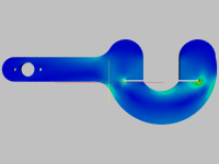
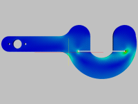
Exactly as predicted (by me!) in both location and magnitude; and entirely within the proof stress of the material selected. (Eat crow why don'tcha!?)

Total strain: 1-layer Post-Processor (Total strain) Screenshot.png

The von Mises Stress:1-layer Post-Processor (von Mises Stress) Screenshot.png

Displacement: 1-layer Post-Processor (Displacement) Screenshot-2.png
 
Buk___ said:
Exactly as predicted (by me!) in both location and magnitude; and entirely within the proof stress of the material selected.


What was the axle torque to produce that stress?
 
Chalo said:
Buk___ said:

That's not a torque, son.
No sh...ugar, Dad. (You cannot specify a torque, so you have to specify the force per unit area that would result from the torque acting on the face!)

But that'll be over your head.
 
Buk___ said:
Chalo said:
Buk___ said:

That's not a torque, son.
No sh...ugar, Dad. (You cannot specify a torque, so you have to specify the force per unit area that would result from the torque acting on the face!)

But that'll be over your head.

It was still a wrong answer to the question.

And would it really be over my head? What do you know about my head?

IMG_20180423_222732.jpg

Evidently less than Mr. B. He brought me in personally as the first outside hire of his own space program.

Who believes in you, son?

Edit: don't bother trying to email me at that address. After about 5-1/2 years there, I quit in late 2006.

P.P.S. -
Those FEM diagrams point up the problems in your design. You may have scaled the colors wrong, you may have made the wrong assumptions about applied forces, but the stress concentrations are there, just as I said they would be.
 
Chalo said:
Buk___ said:

That's not a torque, son.

My thought also. In the diagram, it is not evident to me where this 200N is applied, so you need to help us out.

I am interested in what the amount of torque would be at that stress for comparison reasons. I know how much torque my hub motor can make. I want to know if the design will withstand that much.
 
Back
Top