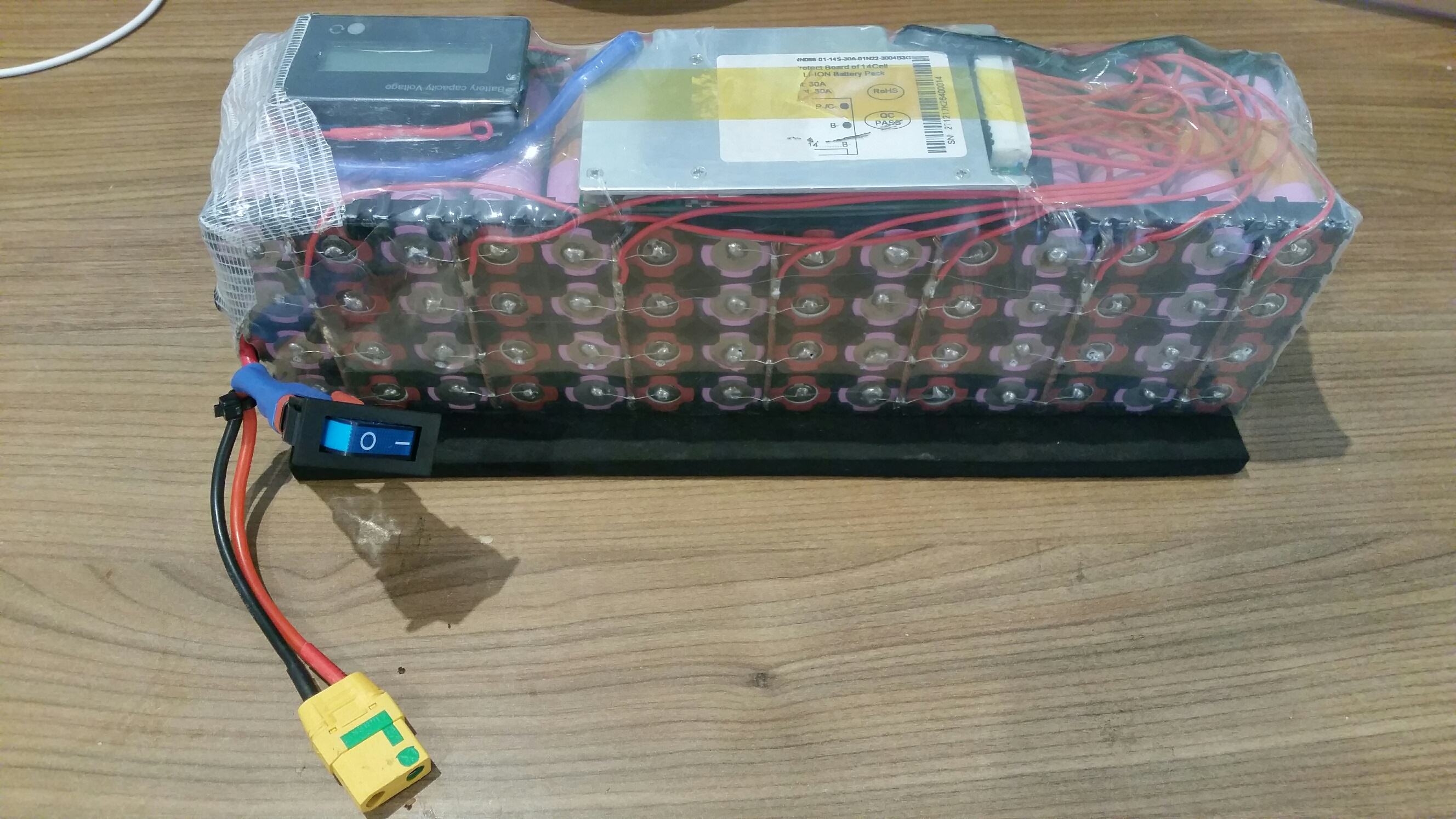
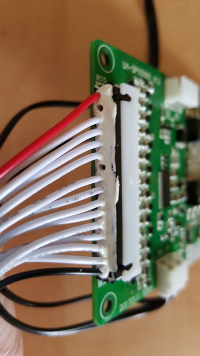
bluetooth BMS?

bres55 that's great info, but as far as i understand this, this is "only" communicaiting with the BMS, the same way the android and pc app do it?!
so it's not a try to reprogram the CPU? as this is something that would be really usefull. imho this BMS is really capable, but not the way it works right now.
the K1 switch, as you said, only seems to disable the output FETs. but the BT module is still fully powered all the time, draining the battery.
of course it makes sense to do so, as you need to connect the phone to the BMS, which only works when BT is on. the problem i see is: IT'S ALWAYS ON. it never shuts down. WHY could that be?
as i read it, it should go in standby and wakeup every 10s and look for a connection, right?
 
That's right, the same info, and the apps look nicer, but I wanted selective data and to be able to switch, charge and dis-charge fets, and control the balancing. These will depend on other data. I'm into powerwalls, but this thread is by far the most interesting related to the smart BT BMSs. If I had better meters, I would monitor how much drain there would be on the pack if the data aquisition time gap was made longer, since I guess the blue tooth is downloading data every couple of seconds.
 
flippy said:
izeman said:
@flippy: afair you have a different version BMS than i have. 15s and 20s are not the same type.
there may be different programming inside.
but still i'd be interested in long term voltage drop of any BMS here. maybe you guys could tell us how much voltage drops within a week. if you ever don't use your bike for that long ;)

i think these BMS's are all the same. the control board and software are identical. its a very modular design and they try and fit the same design and software for virutally all applications they can find.
there might be slight tweaks but the general control and firmware will be the same. that probably means they all have the same issues.
power consumption can be different depending on the board design but i doubt there will be much of a difference.

i have both the 24S and 32S model here of this version:
https://www.aliexpress.com/item/8S-to-24S-2018-new-DIY-Lifepo4-li-ion-50A-80A-100A-110A-120A-smart-bms/32847165991.html

Me too...I have the 24S and 32S of these BMS. They are identical other than the mosfets and a few other details that are specific to the voltages and number of cells involved. Why the manufacturer would dramatically change things between 2 virtually identical BMS would not make sense to me.
 
madin88 said:
ta61dq.jpg

Open up those solder bridges and go into the PC app. I forget the option off hand, but you can then set this BMS to see the maximum channels it has in it's balance connector. Add a couple of balance wires to those holes and you are set.
 
izeman said:
bres55 that's great info, but as far as i understand this, this is "only" communicaiting with the BMS, the same way the android and pc app do it?!
so it's not a try to reprogram the CPU? as this is something that would be really usefull. imho this BMS is really capable, but not the way it works right now.
the K1 switch, as you said, only seems to disable the output FETs. but the BT module is still fully powered all the time, draining the battery.
of course it makes sense to do so, as you need to connect the phone to the BMS, which only works when BT is on. the problem i see is: IT'S ALWAYS ON. it never shuts down. WHY could that be?
as i read it, it should go in standby and wakeup every 10s and look for a connection, right?


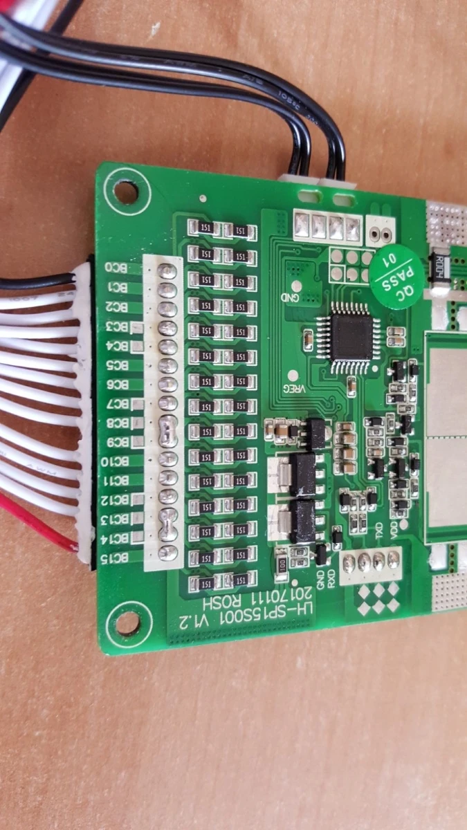
This week I'll pull out my 16S pack. It's been stored in a box for at least the last 2 months. I've been in the process of moving for a while now and am finally in the new house. If there is a loading issue from BT or something else...I'll see it! Actually...who cares if I can physically see the pack or not. It's in a cardboard box. That won't stop BT connection to it.

We ought to be able to see if BT sleeps or not and what kind of interval it uses if any. The BT chip will have an enable pin on it. Does it go low for a while? Does it go hi for a while? THat's your standby/sleep cycle.
 
ElectricGod said:
We ought to be able to see if BT sleeps or not and what kind of interval it uses if any. The BT chip will have an enable pin on it. Does it go low for a while? Does it go hi for a while? THat's your standby/sleep cycle.
can't say it the enable pin is high or low, but at least the BT module is powered all the time. 11v are present at VCC. this at least shows that there are voltage regulators online using power.
 
izeman said:
ElectricGod said:
We ought to be able to see if BT sleeps or not and what kind of interval it uses if any. The BT chip will have an enable pin on it. Does it go low for a while? Does it go hi for a while? THat's your standby/sleep cycle.
can't say it the enable pin is high or low, but at least the BT module is powered all the time. 11v are present at VCC. this at least shows that there are voltage regulators online using power.

True, but typical Vreg quiescent current is pretty low. The LM series voltage regs need like 45uA. This is negligible load on even a very small battery pack. If the BT chip is asleep, then I bet it loads at a few uA too. I don't know what BT chip is used, but it would be easy to figure this out. It looks like BT 4.1 is typically about 22mA active. I didn't see quiescent current draw in my quickie search. Power going to the BT module doesn't mean it is powered up. That 11 volts is regged down to 3.3 volts since that's what BT chips typically use. Sleep mode may be a command instead or a pin on the chip or both. Typical phone CPU's work this way. They can power down via software or via the power button which essentially puts the CPU to sleep.
 
i agree. just seeing voltage on VCC is nothing to worry about. just wanted to mention it.
and taking your 22mA BT active, even this doesn't concern me at all, as it's 22mA at 5V (or 12V). so it's a fraction of that at full packs voltage. so let's assume some 1-2mA @50V+. and this means a 30Ah pack would take 30.000h or 4 years to deplete.
 
Bt sleep mode commands are given by serial commands and are persistent.

The real deep sleep modes are not present on the cheap chinese boards so dont bother.
 
flippy said:
Bt sleep mode commands are given by serial commands and are persistent.

The real deep sleep modes are not present on the cheap chinese boards so dont bother.

That makes sense...comms to the BT board are over some kind of serial bus. And most likely the BT chip is all that's listening on the other end. IE: any low power or standby pin on the BT chip can't be used since it needs to be awake sufficiently to listen to the serial comms as they happen. If anything, it goes into a mode where it turns off TX and RX since they are the power hungry portions of the IC.
 
I tried messing with those cheap bt boards a while back for some weather station ststion for outside with a small battery and solar panel but i could not get the jeeslus thing to go into any deep sleep mode that bt4.0 should have between transmit pulses. It simply does not respond to those specific commands regular sleep mode works fine but it does not enable that LP part of 4.0LP. Better said: you can send the command but it wont lower the power consumption one joule. You need a "real" board/chip for that part to work. My guess is that the chinese simply could not copy that part of that is the part that made the chip more expensive so they just dropped it.
 
Inwo said:
They are both available.
I ordered one with 11s balance modules up to over 100s. Canceled by seller.
The first one you listed is no advantage over the 24s by model.
The second seems bulky and expensive. Nice balance function though.

I ordered these expadandable models.
https://www.aliexpress.com/item/112S-35S-Lithium-Li-ion-LiFePO4-LTO-Lipo-Battery-Protection-Board-BMS-Balance-Bluetooth-APP-7S/32861093603.html?spm=a2g0s.9042311.0.0.xblwJG

Enough for fast shipping. All Chinese, so may be a $300 bust. 😣

He just canceled the order I made 2 weeks ago for 2 of these....
 
I have a 60 amp 14s BT BMS I'm about to install on a DIY pack.
Would adding an on/ off switch like this

KT4ZbUd.jpg


prevent the battery draining when not in use?
 
themelon said:

He just canceled the order I made 2 weeks ago for 2 of these....

Got mine in but not smart enough to program them.
7s through 35s models.
They seem to work.
 
now that my battery is balanced, and that i installed a switch at K1, it seems the bms behaves like it should. all cell are within 2mV and the voltage drop was 1mV/cell after 48h. i guess i can live with that. i'll monitor this over time and see how it goes.
i think the K1 switch was the key to success?!
 
Inwo said:
themelon said:

He just canceled the order I made 2 weeks ago for 2 of these....

Got mine in but not smart enough to program them.
7s through 35s models.
They seem to work.

Seems I might still get them:

hi friend
our manufacturer said another set can be available after 10 days .
so our warehouse staff is waiting another set and plan to ship them together
don't worry. he said when another set available , send out immediately with fastest speed
Yours
Sophia

I ordered 2 35s versions with 2 LCD screens. Still have the opinion that they just might work? Is the 35s version really just 5 identical boards so they can be split up?
 
themelon said:
Inwo said:
themelon said:

He just canceled the order I made 2 weeks ago for 2 of these....

Got mine in but not smart enough to program them.
7s through 35s models.
They seem to work.

Seems I might still get them:

hi friend
our manufacturer said another set can be available after 10 days .
so our warehouse staff is waiting another set and plan to ship them together
don't worry. he said when another set available , send out immediately with fastest speed
Yours
Sophia

I ordered 2 35s versions with 2 LCD screens. Still have the opinion that they just might work? Is the 35s version really just 5 identical boards so they can be split up?

what 35S BMS? This thread covers 2 different kinds of smart BMS, but none are 35S.
 
ElectricGod said:
themelon said:
Inwo said:
themelon said:
He just canceled the order I made 2 weeks ago for 2 of these....

Got mine in but not smart enough to program them.
7s through 35s models.
They seem to work.

Seems I might still get them:

hi friend
our manufacturer said another set can be available after 10 days .
so our warehouse staff is waiting another set and plan to ship them together
don't worry. he said when another set available , send out immediately with fastest speed
Yours
Sophia

I ordered 2 35s versions with 2 LCD screens. Still have the opinion that they just might work? Is the 35s version really just 5 identical boards so they can be split up?

what 35S BMS? This thread covers 2 different kinds of smart BMS, but none are 35S.

Should have put in a link. It is one of the modular alternatives I linked a few pages back.

https://www.aliexpress.com/item/112S-35S-Lithium-Li-ion-LiFePO4-LTO-Lipo-Battery-Protection-Board-BMS-Balance-Bluetooth-APP-7S/32861093603.html

From what I have been able to get from the vendor it uses the same software as the two that started this thread as well.

Off-topic?
 
themelon said:
Should have put in a link. It is one of the modular alternatives I linked a few pages back.

https://www.aliexpress.com/item/112S-35S-Lithium-Li-ion-LiFePO4-LTO-Lipo-Battery-Protection-Board-BMS-Balance-Bluetooth-APP-7S/32861093603.html

From what I have been able to get from the vendor it uses the same software as the two that started this thread as well.

Off-topic?

No not really off topic...it is a smart BMS.

If you want to wait, I have 5 of those boards coming my way. I should see them next week at the latest. I didn't realize we were talking about the same thing. There's aspects of these...errr...BMS that are peculiar.

1. Each "board" is a separate BMS...complete with mosfets and balance circuitry.
2. Since they are each 7S, the mosfets on each board are probably not more than 40 volt parts.
3. the boards can daisy chain together together and communicate over a common TX/RX buss that's something like SATA or USB.
4. the mosfets are small and few so current handling per board will also be low.
5. comms between boards is opto isolated
6. Since they are full BMS each, there is C-, V- (P- on most BMS) and B-. C- has 2 mosfets and V- has 4 mosfets or 2X discharge than charge current. Clearly in a daisy chained situation you would not use the C- mosfets since they handle half as much current as the V- mosfets do.
7. The C- mosfets are LR7843 or 30 volt mosfets. The V-(P-) mosfets are unclear. I can't tell what they are, but it's a different part.
8. All mosfets on all boards need to shut off simultaneously or else you create some possibly dangerous and unpredictable results for the other BMS's that are still on. You want to control the division of the total pack voltage to just the amount that each board can handle.
9. Lack luster current handling...20 amps max.
10. IMHO....this is a balance board and not a full on BMS. the mosfets are pretty useless.

I'll post up detailed pics once I have the 5 boards and LCD and then work on connecting to a 32S LIPO pack I have.
 
ElectricGod said:
themelon said:
Should have put in a link. It is one of the modular alternatives I linked a few pages back.

https://www.aliexpress.com/item/112S-35S-Lithium-Li-ion-LiFePO4-LTO-Lipo-Battery-Protection-Board-BMS-Balance-Bluetooth-APP-7S/32861093603.html

From what I have been able to get from the vendor it uses the same software as the two that started this thread as well.

Off-topic?

No not really off topic...it is a smart BMS.

If you want to wait, I have 5 of those boards coming my way. I should see them next week at the latest. I didn't realize we were talking about the same thing. There's aspects of these...errr...BMS that are peculiar.

1. Each "board" is a separate BMS...complete with mosfets and balance circuitry.
2. Since they are each 7S, the mosfets on each board are probably not more than 40 volt parts.
3. the boards can daisy chain together together and communicate over a common TX/RX buss that's something like SATA or USB.
4. the mosfets are small and few so current handling per board will also be low.
5. comms between boards is opto isolated
6. Since they are full BMS each, there is C-, V- (P- on most BMS) and B-. C- has 2 mosfets and V- has 4 mosfets or 2X discharge than charge current. Clearly in a daisy chained situation you would not use the C- mosfets since they handle half as much current as the V- mosfets do.
7. The C- mosfets are LR7843 or 30 volt mosfets. The V-(P-) mosfets are unclear. I can't tell what they are, but it's a different part.
8. All mosfets on all boards need to shut off simultaneously or else you create some possibly dangerous and unpredictable results for the other BMS's that are still on. You want to control the division of the total pack voltage to just the amount that each board can handle.
9. Lack luster current handling...20 amps max.
10. IMHO....this is a balance board and not a full on BMS. the mosfets are pretty useless.

I'll post up detailed pics once I have the 5 boards and LCD and then work on connecting to a 32S LIPO pack I have.

Good info. There is no way that mine will ship before you get yours so I can always cancel, or at least TRY to cancel...

Even if they just end up being useful as "smart" balance boards with a serial, might be RS485, interface I'm happy with ~$18 per 7 cells. Perhaps a separate "power" board could be designed and used with them in place of the mosfet section if any of us were ambitious enough to do so.

I did finally get one of the TinyBMS's to screw with. Unfortunately about all I have had time to do is look at it taunting me.
 
themelon said:
ElectricGod said:
themelon said:
Should have put in a link. It is one of the modular alternatives I linked a few pages back.

https://www.aliexpress.com/item/112S-35S-Lithium-Li-ion-LiFePO4-LTO-Lipo-Battery-Protection-Board-BMS-Balance-Bluetooth-APP-7S/32861093603.html

From what I have been able to get from the vendor it uses the same software as the two that started this thread as well.

Off-topic?

No not really off topic...it is a smart BMS.

If you want to wait, I have 5 of those boards coming my way. I should see them next week at the latest. I didn't realize we were talking about the same thing. There's aspects of these...errr...BMS that are peculiar.

1. Each "board" is a separate BMS...complete with mosfets and balance circuitry.
2. Since they are each 7S, the mosfets on each board are probably not more than 40 volt parts.
3. the boards can daisy chain together together and communicate over a common TX/RX buss that's something like SATA or USB.
4. the mosfets are small and few so current handling per board will also be low.
5. comms between boards is opto isolated
6. Since they are full BMS each, there is C-, V- (P- on most BMS) and B-. C- has 2 mosfets and V- has 4 mosfets or 2X discharge than charge current. Clearly in a daisy chained situation you would not use the C- mosfets since they handle half as much current as the V- mosfets do.
7. The C- mosfets are LR7843 or 30 volt mosfets. The V-(P-) mosfets are unclear. I can't tell what they are, but it's a different part.
8. All mosfets on all boards need to shut off simultaneously or else you create some possibly dangerous and unpredictable results for the other BMS's that are still on. You want to control the division of the total pack voltage to just the amount that each board can handle.
9. Lack luster current handling...20 amps max.
10. IMHO....this is a balance board and not a full on BMS. the mosfets are pretty useless.

I'll post up detailed pics once I have the 5 boards and LCD and then work on connecting to a 32S LIPO pack I have.

Good info. There is no way that mine will ship before you get yours so I can always cancel, or at least TRY to cancel...

Even if they just end up being useful as "smart" balance boards with a serial, might be RS485, interface I'm happy with ~$18 per 7 cells. Perhaps a separate "power" board could be designed and used with them in place of the mosfet section if any of us were ambitious enough to do so.

I did finally get one of the TinyBMS's to screw with. Unfortunately about all I have had time to do is look at it taunting me.


Main mosfet cut off that can handle lots of current...
This is a very basic mosfet switch, but parallel more mosfets for more current and use 150 volt parts so you can deal with 35S. Connect the gates to the lowest board in the series on that boards V- mosfets gates and it shuts down for everything in the pack and is connected to the "lowest mosfet" controls. I've built several of these for uses in EV's and it's exactly what the P- mosfets do in a BMS. They are useful for turning on a higher current load than the tiny switches on your handle bars can deal with. If you have an old 12 fet motor controller that is dead, the board will make wiring this very easy. You will need to do some rework on the controller board to get all the mosfets in parallel, but that's pretty easy to do. Cut off all the rest of the controller board and keep the section that has the power and phase busses. 12 AOT2500's or IRF4115's in parallel and in full saturation will handle 150 amps continuous easily. Mount them to the heat spreader in the controller and 200 amps continuous won't be an issue.

Mosfet%20switch_zpsoswpslyy.png


This little board is essentially the same thing for peripheral switching. Just pull the mosfets and replace with higher voltage ones and you have 4 channels you can switch.

https://www.ebay.com/itm/4-Channel-Four-Route-MOSFET-Button-IRF540-V2-0-MOSFET-Switch-Module-for-Arduino/282885920247?hash=item41dd5095f7:g:0NkAAOSwJ3RaqqbX
 
I am moved into my new house and found my box of batteries. I had no problem connecting to the BMS on my 16,000mah 16S LIPO pack. My phone connected immediately. My guess is the BT module was either fully awake or in some kind of low power receive only mode.

Current pack status: At 4v per cell that would put the pack at 64 volts and it's currently at 63.04 volts.

3%20months%20-%20basic%20information.png


Cell status: Low cell is now 3.921v and high cell is 3.947v or .025v variance. Clearly I've drained the pack a little just sitting there for 3 months.

3%20months%20-%20cell%20voltages_1.png


Charge history: As you can see all cells were 4.0v or higher when I charged last in mid February

3%20months%20-%20charge%20history.png


Conclusion: Sitting there for many months will drain out the pack eventually, but it looks like it will stay fairly well balanced as it happens. In 3 months of sitting I lost .985% of charge or about .01% per day. It's going to take a good while...well more than a year to run down the pack.

The pack...

P1020036.jpg
 
madin88 said:
flippy said:
i think these BMS's are all the same. the control board and software are identical.

i have both the 24S and 32S model here of this version:
https://www.aliexpress.com/item/8S-to-24S-2018-new-DIY-Lifepo4-li-ion-50A-80A-100A-110A-120A-smart-bms/32847165991.html

Are you sure?
The software looks different (at least from the pics), and the circuit boards as well.

btw:
I own the 13s 30A version which is, aside from two solder joints, identical to the 15s version. The junctions are between input 8-9 and 13-14 (see pic).

I have not as yet wired it up, but i could imagine that if the BT module is permanently attached that it drains more current as if it's not, but thats only a guess.
If there really is a problem with too high current draw even if the BT module is disconnected and on top of that if it's even turned off with the optional on/off switch, than these BMS's are garbage!

ta61dq.jpg


JKx5z1.jpg

does it go well for lto batteries? I made this question a bit around and someone answered me that the low voltage cutoff range is 2.0 to 3.3 volt and overvoltage 3.6 to 4.3v (but for lto undervoltage is 1.8v). Do you confirm?
 
e3s said:
does it go well for lto batteries? I made this question a bit around and someone answered me that the low voltage cutoff range is 2.0 to 3.3 volt and overvoltage 3.6 to 4.3v (but for lto undervoltage is 1.8v). Do you confirm?

This BMS will do LTO. The voltage ranges in the control logic are capable of LTO requirements. BTW...buy from IC GOGOGO like the below link. The other seller listed in your post is some knock-off seller. Supposedly there are problems with them.

https://www.aliexpress.com/store/product/Smart-Display-300A-8-24S-Cells-Lithium-Battery-Protection-Board-Balance-BMS-Coulomb-Meter-Lithium-iron/2856009_32827394534.html?spm=2114.12010612.0.0.16f73de2z48IFR

This one however has a LION TI chip in it and looking at the spec sheet for the part, won't do LTO voltages and you can't set them in the app that low anyway.

https://www.aliexpress.com/store/product/20S-Lipo-LiFePO4-Lithium-Battery-Protection-Board-60V-72V-Li-ion-Cell-Smart-Phone-APP-PC/2856009_32863752220.html?spm=2114.12010612.0.0.16f73de2z48IFR

Tracking shows my latest BMS purchase will arrive mid next week. That's this LTO capable product. Current handling is lack luster, but I bet with better mosfets and some added aluminum that I can bump that to 40-50 amps easily.

https://www.aliexpress.com/store/product/112S-35S-Lithium-Li-ion-LiFePO4-LTO-Lipo-Battery-Protection-Board-BMS-Balance-Bluetooth-APP-7S/2856009_32861093603.html?spm=2114.12010612.0.0.48c93de2XEEg0S
 
Back
Top