Amberwolf's Raine Trike

Would've been a good day to do the wood stuff, but before I got started on that I took a look at the SB Cruiser to fix a squeak that has been annoying me for a while (several weeks), only to find it wasn't just a squeak.
https://endless-sphere.com/forums/viewtopic.php?f=2&t=67833&p=1339930#p1339930
file.php


By the time I was done with all of that repair, it was sunset, and getting chilly (mid-60's F) and dark, and I was very hungry (never got around to eating anything today), and I'm still getting over a head-cold too. So I didn't get antyhing done on the Raine Trike. Maybe next week.
 
All frame welding is now done, and the frame is now primered and painted Italian Olive Satin (Raine's color of choice). As a test some of the frame, the wheels (rims, spokes, motor/hubs) and front fork were painted an Olive Drab that is more like a "modern" military olive color, but Raine didn't like that so the other was used on everything except the wheels, which were left as they were mostly because there wasnt' enough of the Italian Olive to completely redo them. (had to save some paint to cover the additional bits yet to be added for the pedal drivetrain).
dsc06923.jpg
dsc06927.jpg


He hasnt' decided if the wood is going to be painted to match the frame, or just sealed/stained, or left bare to age in the weather. Once I get the wood cut and installed, he can see it and make a decision.


I'm still working out the pedal chainline, but the cranks are now finalized. I ran across the old cranks from SB Cruiser (which originally came from Delta Tripper, and some cheap bike before that), and took the BB shell from a junked BMX frame (because these cranks are larger diameter bearings/core shaft than the ones off the kid's bike I started with--though the chainring on them is exactly the same, by whatever chance; the pedals themselves are smaller diameter threaded part than the kid's cranks).

The kid's cranks I had just tackwelded temporarily by the stubs of chainstay I'd left on the BB shell, to get the positioning right, fitting the seat and other frame stuff so it'd be a good reach for Raine.

When I took the BB shell of the BMX, I kept a few inches of downtube and seattube. I cut a notch in the center of the downtube, to fit it around the keel of the trike, and angled the seattube end to fit against the face of the keel below the BB. It's positioned so the center of the cranks ends up where the center of the kid's cranks were.

Then I added the "triangle" like I have on SB Cruiser, partly to strengthen the front end a bit, and partly to have a place to hide some of the wiring/etc in up front. It doesn't have the "toptube" over the lower keel, though, because Raine needs a much lower clearance than I do to step over it.


Also have to make up the wiring harnesses for motor stuff and lighting stuff.

Raine hasn't ordered any of the lighting stuff yet, so I don't know what it will need for mountings.


The dogs were, as usual, pretty bored with the whole thing.
dsc06928.jpg
dsc06929.jpg
 
In sorting out the shed stuff (see the old housefire thread) last week, I found the U-joint piece I was considering using as the transfer axle from the pedal chainline in the center to the wheel itself, which is cambered in at the top so it might be easier to align with the U-joint vs a straight (angled) tube.
dsc07142.jpg

Havent built the rest of the chainline pulleys anyway yet, to route the chain down from the cranks, and under the trike to go back to the rear wheel. These will probably be made from ex-rear-hubs, bolted (or welded) to the frame, with old freewheels with pawls removed (so they can be rotated backwards). Considered stuff like derailer jockey wheels or notched nylon/etc wheels, but there will be a lot of tension on these things, and I think I'll get better alignment and quieter


Also put the tiedown cables to be used on the rear corners of the canopy to tie them to the rear corners of the deck frame, so it doesn't wiggle around and eventaully break the thin alumnum tubing.


Still looking for all the old brake bits to put on the rear wheels and frame (front brake is ok but won't be enough in every situation, and with a geared hub it can't be used to regen brake). Found most of my cabling and housing few weeks back when I fixed up SB Cruiser's front brakes, so just have to find all the stuff with salvaged bosses and arms. Pads Raine will have to buy new; I don't have any old ones that are any good anymore (dryrotted or hardened, or just worn out).


Still haven't cut the wood for the seatbox/etc. Gotta get that done, cuz until it's all installed, there's nowhere to bolt the controller/etc to (under the box), or any place to put the switch/breaker, battery, charger, etc. (which all goes inside the box). Until those are installed, can't easily make the wiring harness, as I won't know exactly how long the cables need to be.

Did also find the latches and hinges (not pictured) to be used on the lid. Will probably have a regular padlock and hasp to secure it, since I don't have any more cabinet locks with keys (got a lot of locks from old IBM PS/2 and AT cases, and a lot of keys for same, but none fo the keys fit any of the locks).
dsc07152.jpg


Also harvested a pile of switches of various kinds from a few old aircraft panels a friend gave me years ago, that sat out in the weather for years before I got them. I think they were 737 cockpit engineering station panels; don't recall. No pics of the panels, but here's the stuff I saved (bunches were too damaged to be worth trying to take off), many things were already removed before I got them). Some of these will be used on this trike for lights/etc.
 

Attachments

  • dsc07145.jpg
    dsc07145.jpg
    78.7 KB · Views: 2,273
  • dsc07146.jpg
    dsc07146.jpg
    53.6 KB · Views: 2,273
  • dsc07147.jpg
    dsc07147.jpg
    49.7 KB · Views: 2,273
  • dsc07148.jpg
    dsc07148.jpg
    40.7 KB · Views: 2,273
  • dsc07149.jpg
    dsc07149.jpg
    42.5 KB · Views: 2,273
  • dsc07150.jpg
    dsc07150.jpg
    38.2 KB · Views: 2,273
I got the wood cut and glued and clamped for the seatbox lid. While it's drying, I also drilled the mounting holes for the powerchair seat, and bolted it to the lid, to help hold it in shape (flat) since teh wood itself is warped a bit.

It'll dry like that until I next get the chance to work on it, which could be a while, then I'll mount it to the seatbox frame with a piano hinge. After taht I'll be clamping and gluing in the wood to the rest of the box frame.

While I was clamping it up, I'd kneeled down beside it for a reason I don't remember...because one of the 4-foot-long bar clamps sprang off of it and whapped me upside the head hard enough to make me see tweety birds, and took me probably a couple minutes to regain awareness of where I was and what was happening. No blood, but my temple is probably gonna be all sorts of pretty colors tomorrow morning (it's pretty sore, though not swollen, from about my cheekbone up to the top of my temple, and just at the left edge of my orbit to just behind the rear of my temple).
 
Finished up the seatbox's lid with the seat bolted to it--at least, teh wood parts. Still ahve to put the hinges on it and bolt them to the frame, then get more wood cut and installed in the rest of the seatbox.
dsc07284.jpg
More pallet wood processed.
file.php


file.php


Some of the wood is split, so I have to glue and clamp it flat while it dries.
dsc07275.jpg
 
The seatbox lid (built in last post above) warped diagonally, up at the front left and right rear corners, in the couple weeks or so since then. So I unscrewed and pried off the right side "beam" under it, that holds all the boards together, then sanded that beam's mating surface into a curve opposite that of the warp, then clamped the lid flat to the frame and glued and screwed teh beam back down to it. That's fixed a part of the warp. Have to do the same to the other end's opposite corner, and see if that fixes the rest of it, but won't happen till next weekend most likely.

While it was clamped flat, I also planed the worst of the plank-height differences off, and then belt-sanded most of it fairly flat and smooth, enough to then seal & stain with the same stuff I used on SB Cruiser's wood (since Raine prefers that to painting it).


I also cut, sanded, and tapped / glued into place the boards to fill the front and right side of the seatbox, leaving the thin plywood sheet as the bottom of it screwed into holes drilled into the frame. The sides are glued to that sheet, and to each other. They're glued into the frame, too, but most of what holds them there right now is a fit so tight they had to be tapped into place with a mallet.
dsc07315.jpg
dsc07318.jpg
dsc07319.jpg
dsc07320.jpg


Rough-planed/sanded the surface of those, too, then sealed / stained them the same as the top.
dsc07334.jpg
dsc07343.jpg


Still have to make the left end and the back, and then install the hinge and lock on the seatbox lid.


Controller is now mounted, just right of the main keel, under the seatbox. Started running wiring for some of the controls/etc, but didn't get very far yet. Just enough that the wires are connected and partly tied down, and the trike can be ridden.


Pedal drivetrain is still not designed and built. :/


Some comparison pics next to SB Cruiser, with some magneically-0attached lights I used on the around-the-block test ride:
dsc07321.jpg
dsc07322.jpg
dsc07323.jpg
dsc07324.jpg
dsc07325.jpg
dsc07326.jpg


Assorted other pics
 

Attachments

  • dsc07327.jpg
    dsc07327.jpg
    25.2 KB · Views: 2,147
  • dsc07329.jpg
    dsc07329.jpg
    28.5 KB · Views: 2,147
  • dsc07330.jpg
    dsc07330.jpg
    25.1 KB · Views: 2,147
It's actually ok so far, though with the wimpy little geared motor ;) and it's tiny sensorless controller that takes time (and banging noise) to determine which way is forward every time you apply throttle, it doesn't take off real instantly from a stop, despite being much lighter than SB Cruiser.

The seat is at least 40lbs, maybe 50, so it probably weighs as much as most of the frame. :lol:

As long as I'm at lowish speeds, 5MPH or less, I can make a complete circle turn in something just over the length and-a-half of the trike I think it is.

Can make regular right and left turns on streets at at least 12-13MPH before it gets tippy, which is pretty good, though not good enough yet. I think I can do better once the rest of teh permanent stuff is mounted, which will add some weight low and to the sides. But once the canopy is completed, it's going to make it an issue when it's windy in the wrong directions.

Hasnt' been taken out in real traffic yet, until it gets ligths and turn signals / etc., and good brakes (still using the pads that probably came with the Velcro Eclipse's base bike when it was made in the 80s or 90s, so they're just little chunks of rock rubber; cuz that's the fork I'm using on the front).


As for my determination...well, nobody makes what I want / need, so if I don't make it myself I won't have one. And I can't afford to pay someone else to do it (or I'd probably contract out a lot of stuff cuz I'm just not very good at it).
 
The seatbox is complete, including latches and lock and hinges.
dsc07370.jpg

dsc07369.jpg

The traction battery and lighting battery are mounted, held in place iwth blocks of wood screwed to the seatbox panels (same way I did it on SB Cruiser), and the charger is mounted above the traction battery (seatbox lid must be left open to charge), and breaker/switch/shunt (for CA if I put one on for testing purposes) are mounted and wired in.

dsc07368.jpg

Since Raine hasnt gotten any lights or mirrors / etc yet, I temporarily pulled all the stuff of CrazyBike2 to put on this trike, since if I redo CB2 Id want to rewire and remount stuff anyway, as CB2 was really a disaster for wiring :lol: from all the changes and experiments over the years.

I got the lights physically mounted, and started wiring up the front stuff, but all I got working so far was the headlight. Even that took more than it should, because the switch Id used for years on CB2 just fell apart when I was putting the nut on it to attach it to a plate on the trikes frame, so I had to dig out another siwtch, which wont fit in that plate without drilling a bigger hole.

However, the Makita battery powered drill/driver had chosen the day before to have its clutch (presumably) fail. (it spins with no load, but even a finger on the chuck will stop it, though the motor and gearing inside still sounds normally spinning). Thats the only chuck on a working drill (besides the lathe or the drill press) that will hold a bit bigger than 1/4 inch diameter. The new switch is about 1/2 inch diameter for its threaded area. I could file the hole out with a round file, but decided to just ziptie the switch to the frame since this si all temporary anyway, till Raine decides what lights he wants and gets them.


I dont know why, but the turn signal blinker doesnt work. Wired it up the same way as on SBC, but no output. Popped the cover off and see no corrosion from water ingress, or any other visual issues; maybe have a poke around in it with a meter later.

Also, I think the (3-4 decade-old) turn signal switch has failed inside on the righthand signal position (the left works), as wehn I connect the common directly to power and switch, it doesnt light up the righthand front singal but the left does. If i hook up the righthand signal directly to power it does work. Continuity is fine between signal and switch wire, so that leaves something with the switch most likely.


Ill get back to it tomorrow, and wire up the rear stuff, then see about getting a new flasher unit and replace the switch with a toggle (or rocker) if have one laying around that will fit it. THen at least itll all be wired up, and once a blinker is installed, itll be ready to go. In the meantime I can jumper across the power and output pins of the blinker spot, so that the signals can be flashed manually by toggling the signal switch repeatedly.


Progress is progress.
 
I have a few plastic boat seats that would work well for a trike seat. One has a padded waterproof seat with half backrest that folds down the other is the cheaper one piece molded variety with backrest. The one piece could be covered with closed cell foam covered in marine vinyl.

The seats weigh 5 to 7 lbs each the one piece costs around $20 $30 or $5 - $10 used.
Molded race seats can be found cheap as well. Something light would suit the bike.
 
Already has a comfy seat Raine likes; see previous posts for pics and details.


I got the wiring finished today, although I kept running into problems, most of which I kept creating for myself with stupid mistakes.

Everything is mounted now, and ready

dsc07371.jpg
dsc07372.jpg
dsc07373.jpg
dsc07374.jpg

headlight is one bolt on a tab so it can be bent and truned to aim it
dsc07375.jpg

wirin is a tied up rats nest like sb criser in the front triangle, still to be hidden by wood panels someday
dsc07376.jpg
dsc07377.jpg


First, I found the turn signal switch wasnt bad, just that Id mixed up the light blue right turn signal wire with the pale green horn wire, probably because the light from the main yard light is greenish and made them look similar. :/ Or because I was tired and got stupid, dunno which.

Then I somehow mixed up the wires for the brake light and right turn signal when wiring to the rear ligth cluster. :? I have been making a diagram with each wire labelled as I go, and STILL mixed those up.

Once I got all the wiring fixed, I thought, heck, why not just try the turn signal unit again, and bam--it works too. I ahve no idea what I did with its wiring last night that kept it from working, but it does now.

The last thing I messed up I didnt notice until Id taped up and ziptied down all the wiring harnesses, but its minor enough Ill leave it for now: the light switch on the handlebar control for hi/low beam is used instead for turning the power to all the lights (except headlight, which has its own toggle siwtch down on the frame like SB Cruiser). My mistake is that somehow I wired the turn signal power to be always on (to the wrong side of that switch). Since the blinkers dont take power unless theyre on, it doesnt really matter. But its yet another annoying mistake.

since the left rognt turn signal cover is missing (broken years ago) I taped three pedal reflectors over it
dsc07384.jpg
dsc07385.jpg
dsc07386.jpg
dsc07387.jpg

The rest of the styrofoam is now also installed inside the seatbox, so other than bolting the seat back onto its lid, its complete.
dsc07378.jpg
dsc07379.jpg


I also put an old snuggy from a dogfood manufacturer (handed out at work a few years back) on as a temporary canopy cover, until Raine decides what to use and makes it. Its ugly, but functional.
dsc07388.jpg


Touched up some welds, ground some edges smooth, etc., touched up some paint here and there. Kirin suprficed all day long
dsc07393.jpg


needs new brakepads
dsc07381.jpg
dsc07382.jpg

All thats really left is the pedal drivetrain. I got the box of parts out that Ill be using for it, but thats about all I managed for today.


so now its a two trike bikeport on the back porch

dsc07400.jpg

dsc07398.jpg
 
The pedal drivetrain now works; theres a lot of pics and stuff, so its split up into a few posts.

Yesterday I got the front redirection sprocket setup built and installed, and thats it, because it took me hours to get the bits needed out of stuff I had, and a quarter of that time just to get a freewheel apart to take the pawls out (and to put it back together after cleaning and packing with grease since theres no pawls to get stuck by it).

(The freewheel has to have no pawls because it has to be able to spin both directions, or the trike wont be able to back up.)

The mount for the freewheel is one of several identical rear hubs out of junk steel wheels (some rusty), with the unthreaded end cut off.
dsc07401.jpg
Then a chain was prepared with the right number of links to wrap the pedal chainring and the largest sprocket on the freewheel, and place the center of the freewheel as close to the center of the trike keel at the point directly below the pedals where the keel changes from straight to up-forward.

Then a hole was bored at that point thru the 4 layers of the steel of the so the core of the hub shell goes thru that and is welded on both sides of the keel (to make the whole joint stronger and better take the transfer of forces from the chains).
dsc07402.jpg
dsc07403.jpg


Then the freewheel was threaded onto the hub, with the chain already wrapped on the sprocket, so its tensioend but not too tight.
dsc07406.jpg
dsc07407.jpg
dsc07408.jpg

So thats about 1/4 of the pedal drivetrain.
 
Next up was adding a derailer (most likley only to be used as a tensioner, but if I can work out shifting with such a short chainline it will have, thatd be nice too). Idve just used a wheel with 3-speed IGH hub instead, but the plan is to replace this wheel with the Ezee geared hubmotor once its built into a wheel, so the trike will be 2WD both for more power if needed to get started quicker / haul stuff, and for redundancy.


All Ive done so far is just a quick workup of it, by drilling a hole in the dropout plate just forward of teh actual dropout, so the derailer mounting tab will align with the dropout making it easy to get teh axle in and out if necessary to change tires/etc. Then the bolt on the derailer tab that usually goes in the dropout slot is repalced with a regular nut/bolt that goes thru the hole in the tab and the dropout plate.

This mounts the derailer about 180 degrees out of position it would usually be in. If I want to shift it I will probably have to change it to 90 degrees, which will put its slot crosswise to the dropout slot, making it harder to get the wheel in and out when its necessary.
dsc07439.jpg


After Id done the two above things, I started to dig out the pieces to make the transfer axle from the center of the trike out to the left wheel. The original plan was to use a U-jointed shaft between them to make up for the angle difference (since the wheel is canted the drive sprocket has to match that or itll derail the chain. But I realized Id have to make pillow blocks and bearings for it to ride on, and the only bearings I have large enough to fit around it are crank or steerer bearings.

If I have to use those anyway, why not just use a steerer and headtube, etc?

So I dug out the old super-tall frame I already used some pieces from on SB Cruiser, and took its headtube and its forks steerer tube. Id lost the bearings and stuff however, dunno when or where, so had to dig thru my bag of leftovers. The first set I found turned out to not actually be a set, but didnt figure that out till I had cleaned them all out, greased them up, and installed them. THen I found the top end would stick if it was tight enough to not wobble around.
dsc07409.jpg
Called it a night at that point, cuz I just couldnt think straight anymore, after the days heat (actually its been near 100F all week, and actually at/above 100F both yesterday and the day before--thats about 15 degrees hotter than it should be this time of year (or more)...and its only been this hot this week, during my week off, and will be back to normal next week when I am back at work, of course. (and was normal last week as well).
 
Once I found the right bits for the headset bearings to use for this, I started working out how to attach the sprockets to each end.

I could weld one to the former crown end, but cant do that to the other end, because thats the end the cap threads onto to let me take it apart for maintenance/greasing/etc. So I looked around for tubing that would fit perfectly inside the steerer tube, that was also strong enough to take the side loading from the chain and not bend. Couldnt find anything that fit both qualifications, but the closest was a solid steel rod that used to be a grounding rod for a house, IIRC (it has a number of holes in it for wires to insert into and wrap around, and one end is sort of pointed (kinda rounded off from being pounded into the ground) and the other end is spread out like a nail head from being hammered on to get it into the ground. I cut a lenght off to use for this....
dsc07410.jpg
It wasnt large enough to fill the tube, but I also had some very thin walled tubing, which I cut into sections and sliced lengthwise, so I could use them as shims around the rod to make a good friction fit.
dsc07415.jpg

I tack welded these onto the rod, one set near each end, so they woulndt move around, then ground those tacks smooth so they dont interfere. Then the rod will fit firmly but not tightly, so I could move it in and out while experimenting with input sprocket mounts.
dsc07411.jpg
dsc07412.jpg
dsc07413.jpg
dsc07414.jpg
dsc07416.jpg

Next up was making the moutning areas for sprockets round; I didnt want to move all the stuff around the lathe, so I just held the angle grinder on the areas, letting the grinder wheels rotation spin up the shaft being ground, making it its own lathe. Didnt take long and it was round enough for this purpose, enough I couldnt see whatever out of roundness it still has.
dsc07421.jpg
dsc07418.jpg

Then I did a similar thingfor the flat just below the crown race, so the sprocket will sit flat on it and be level.
dsc07422.jpg

I have a few sprockets that are from one-piece (ashtabula) cranks, all of them have a hole just the right size for the crown end of the steerer tube (sligthly smaller, but perfect after self-lathing the tube). The one pictured is a double ring; I ended up using a single ring much smaller, I think it was 30T or 28T, dont remember for sure. dsc07424.jpg


Then I had to find something to moutn the sprocket on the other end. Was harder and took longer, but eventualy I ran across the old powerchair motor sprocket unit Id made for CrazyBIke2 years ago, before going to hubmotors on it. Turns out it is exactly perfect fit for the rod....


dsc07431.jpg


It has a keyslot, so I could make another in the rod, and make a key, to lock it rotation-wise. To lock it against axial movement, there are already holes in the rod, so I can drill matching holes in the sprocket collet, and run a small bolt thru them; it wont have ot handle the torque just axial placement.
 
Next up was making a mount to connect the headtube piece to the trike frame, at the angle necessary to match the wheels angle for chain alighnment. Some square tube at one end, along with a flat plate for angular bracing, and a couple of sections of seatstay off the same frame, will take care of that.

dsc07432.jpg
dsc07433.jpg
dsc07434.jpg
dsc07435.jpg
View attachment 4
dsc07437.jpg
 

Attachments

  • dsc07438.jpg
    dsc07438.jpg
    54 KB · Views: 1,951
  • dsc07446.jpg
    dsc07446.jpg
    45.2 KB · Views: 1,951
  • dsc07447.jpg
    dsc07447.jpg
    48.7 KB · Views: 1,951
Now I had to fix teh rod to the steerer tube, with something that can take the rotation torque. Since there are those holes in the rod, I drilled matching holes in the steerer tube, and put the thickest nails I have thru them (at least, thickest that will fit in the holes).
dsc07443.jpg


Then I welded those to the steerer; it leaves a good portion of teh rod out past the threaded end.
dsc07444.jpg

For good measure I also ground a hole at each end of that area, and welded thru the hole into the rod at the highest welder setting, at a high enough feed rate to fill the hole with weld and ensure the two pieces are connected securely.
dsc07445.jpg

Itll probably hold up; if it doesnt I can take it apart and try something else.
 
Finally finished enough to put it upright, and found a problme I thought I had worked out but apparently screwed up anyway---the input sprocket on teh shaft is only about half an inch above the ground. Way way too close--even on perfectly level ground a flat tire would put it below ground level, and no road around here is level.

dsc07449.jpg
dsc07450.jpg
dsc07453.jpg


But I went ahead and used a piece of one of those nails above, that Id cut off before welding them into the steerer/rod, and hammered it into the keyway slot and the notch Id ground into the rod there. Then I test rode it around, and it worked, other than groundstrikes frequently, that dug into the dirt/grass.

With it setup like it is, ground clearance is impossible, but the chainline clears the frame completely, at the front bottom edge of the seatbox.

dsc07455.jpgdsc07456.jpg

dsc07454.jpg
 
Only real option was to shorten the supports, and move the whole unit up a couple of inches.

It does fix the clearance problem, but it puts the chain up against the frame at the front bottom seatbox edge.

There is still a derailment problem on bumps, which always happens at the input sprocket, so Ill need to work out something to capture the chain onto it, then it should be all set.
 

Attachments

  • dsc07459.jpg
    dsc07459.jpg
    56.5 KB · Views: 1,949
  • dsc07461.jpg
    dsc07461.jpg
    50.4 KB · Views: 1,949
  • dsc07463.jpg
    dsc07463.jpg
    49.1 KB · Views: 1,949
  • dsc07464.jpg
    dsc07464.jpg
    29.7 KB · Views: 1,949
  • dsc07466.jpg
    dsc07466.jpg
    25 KB · Views: 1,949
  • dsc07467.jpg
    dsc07467.jpg
    39.9 KB · Views: 1,949
  • dsc07469.jpg
    dsc07469.jpg
    36.8 KB · Views: 1,949
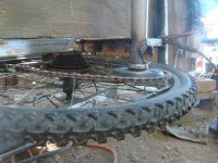
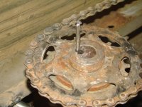
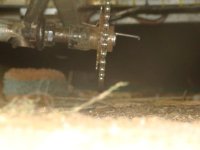
Removed a couple links from the rear wheel chain to let the derailer tension it better, so that fixed the problem of it coming off the drive sprocket on bumps. Still cant shift gears, so its stuck in second, as the chainline is too short to allow proper flex, so it comes off the slack side of the drive sprocket as the derailer moves to shift to the next gear on the wheels cluster, whether I shift down to first ot up to third.

Is pedalable in the gear it has now, by either Raine or me, so no problem at the moment, though itd be nice to be able to shift it down one at least.

Unfortunatley my chaintool (Sunlite something or other, was a pretty nice one thats worked great for years) mustve gotten some tiny bit of grit or something in the threads, because it suddenly jammed up while trying to force the pin out of the first link, and could not be turned at all,forward or reverse. I had to hold one of its hex-shaped surfaces with a box wrench while using the closed end of another as a lever on its T-handle, to force it to turn far enough back to get the partly-sprung link out of it. I couldnt get it any further than that; its toast.

Since I was stuck with the link partly undone, and not really wanting to have to hammer it back in (have done that before for a roadside repair) I spent a couple of hours and built a sort of chaintool out of some other threaded bits I had laying around, a broken drill bit, and the remnants of a previous broken chaintool, and it worked well enough to finish getting the pin out of that link, and out of the one at the ohter end of the seciton to remove, and then fix the chain back together (as I dont have any master links right now).


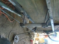
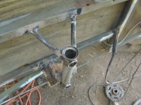
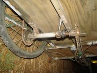
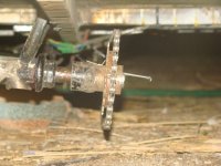
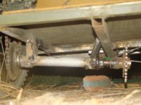
Then I fixed up a tensioner for the long chain that runs from the front to the transfer axles input sprocket, by putting an old derailer around both top and bottom of the chain run. Its not the most efficient way to do it, but it works, until I think of something better. I used an old axle and its nuts and locknuts to mount the derailer to the keel, and hold it out over where the chain is (a few inches to the right of the keel).
dsc07472.jpg


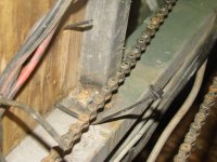
Then, since I dont have any good pads for the old center pull cantilever smooth post brakes, I changed them out for Vbrakes (couple of the old Tektro arms from the stuff Oatnet sent a few years back), and used the old Koolstop pads off CrazyBike2. Theyre worn but still work for now, much much better than the old rocks I had on the centerpulls. Raine has new pads for them on order to replace them, along with some waterproof LED strips for downlighting and taillights/etc in the rear.


I rode it around the yard a few times, and had no problems, even pushing it backwards, so I called it ready to ride, and Raine took it out for a spin around the neighborhood. I followed on my trike, in case anything broke (nothing did) or needed adjusting (a few things did, mostly brakes and mirrors)

He had a lot of fun with it, enough to go back out a bit later for more. :)


Later I guesstimated the spoke length needed for a 1-cross 26 inch wheel using hte Ezee hubmotor, as around 190-ish mm, then looked thru various wheels saved for parts to find the closest ones to that. These two old BMX wheels were very close so I disassembled the bent up one for all the spokes that were still usable, then pulled more from teh other wheel as needed.
dsc07473.jpg

They turned out to be perfect, tensioned up with the spoke ends just about level with the slot in the nipples. Started out round enough and just had to be trued side to side, which is within a couple mm as of now.
dsc07474.jpg

Will work on it more some other time, then put a tube and tire on it, and swap it out for the left rear wheel, so itlll then be a 2WD trike, both for the extra startup power, smoother startup (cuz the Fusin is crap for smoothness since it has to determine rotation direction every time you reapply throttle from zero, even if the wheel is moving) and for redundancy.

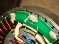
Not sure which controller will work best with it, but I have a couple little 6FETs to try, and a couple old Fusin controllers. If I have to I can take the little board that makes it sensorless out of the spare Fusin 1000w controller and use that.
 
Mounted a tube and tire on the rim, and the wheel on teh trike to replace the plain bike wheel on the left side, then tested with a couple controllers.

So I could be sure I was getting normal operation, I hooked up an old CAv2 small screen (which doesnt quite read current/voltage correctly, but is good enough for relative value use like this), with an external shunt Id put into the battery-controller wiring, that Id taken off SB Cruiser when I hardwired SBCs stuff. This shunt also had a PP45 charging port, which being on the controller side of the shunt meant I could also use it for the second controller power source, and it would be switched on/off with the first one.

First up was the old Grin 6fet I used to use on CrazyBike2s front wheel for a while right after the housefire; this was tested first simply because it has the same connectors as the Ezee motor, which originally came from Grin as well, for the owner prior to me. So theoretically it was likely to just plug in and work, if the motor was operational.

However, as the previous owner had advsed me was likely, it did have a hall sensor issue (though it turned out not to be the halls themselves), and did not operate at all with the Grin 6FET. I checked with a meter and found all the hall voltages the same, at 4.95v, at the motor side of the hall connector (wich means the contacts were good),

So just to test the motor, I tried the 12fet sensorless generic I used to use on the SB Cruisers right wheel. It worked, a bit, but it didnt run normally every time. Sometimes it would startup and apply power as expected, and sometimes it would be very high pitched and low power.

I figure that most likely has to do with the ERPM of the geared motor being too high for the generic controller, but wont know till I can fix the halls and test it with the Grin controller.
 
Today I began working on the motor itself. First thing was to take the cover off; easy enough with just philips screws, and everything pulled apart easy after that too, so some pics of the insides :


Theres some corrosion, mostly mixed with the grease for the gears, but its pretty clean other than that.
dsc07476.jpg
dsc07477.jpg
dsc07482.jpg

Next up was continuity testing from contacts to pins of the halls on the PCB, and found that power and ground had continuity, but none of the three signal wires did.
dsc07479.jpg

I poked and wiggled and probed various spots, but nowhere along the wire length did it have any contact from PCB to wire.

I lifted the glue on the PCB-to-wire connection point, and all three of those wires came with it--they were not really soldered to the PCB pads, and whatever moisture had caused the little corrosion elsewhere in the motor probably oxidized the poor connection there. The power and ground wires were soldered a little, and didnt lift away completely, but they did partially lift and I was able to peel them off the rest of the way without damaging the PCB pads, indicating they werent soldered well either.
dsc07485.jpg
None of the wires were fed thru the holes in the PCB, just appeared to be tack-soldered onto the surface of the pads.

So Ill have to resolder those wires, then retest it with the sensored Grin controller; I suspect it wlll work a lot better than the generic sensorless.
 

Attachments

  • dsc07493.jpg
    dsc07493.jpg
    53.8 KB · Views: 1,861
Resoldered the wires, verified hall operation is normal.

Installed on trike and tested off-ground with an old Grinfineon 6FET using color-matching wires which just made funny noises, and all possible phase combos (since theyre PP45s and easy to swap, but the halls are JST so not), no combo worked correctly. One runs forwards, but it is incredibly fast, and the controller gets hot in my hands (the phase wires dont); a couple run backwards, one at super high speed and one that sounded normal, so I used the reverse wires on the Grinfineon but it still ran hot. Neither forward scheme had the power to start the trike moving on its own, and it could barely keep it moving at the max current of the controller. :/

So I tried this scheme
https://endless-sphere.com/forums/viewtopic.php?f=2&t=6241&p=516172&hilit=ezee#p516172
which did work a bit better, but its still extremely weak for the nearly full controller current it draws, and the controller gets hot rapidly.

Ill have to simply go thru all the combos for both hall and phase, and see if one actually works (and use the reverse jumper on all of the reverse combos to see if any of them work). If none do, Ill try a different sensored controller, with all the combos on it. I ahve a few small ones (6FET mostly, I think one of the Fusins is 9).
 
I still had to fix the pedal chainline issues with the mtoro wheels cluster, and after some trial and error the best fix turned out to be to take the derailer and pivot its hanger even further clockwise than it already was. This required moving it up and forward of the dropout slot, since it wont line up with the axle anymore. I may bolt it into place eventually but for now it is tack welded in place. This fixed all of the issues using it with the larger first gear (actually first two of the motors cluster, just first of the regular wheels cluster), including that of rotating the pedals backwards to reposition them, which before this often stuck on the sprockets and then derailed.

Still doesnt shift gears right, but it may simply be too short a chainline to do that. I might have to move the transfer axle back 6 or 8 inches to get a bit more chain between it and the cluster. May not help much, but might get me 2 or 3 gears instead of just one.

If I thought the pedal drivetrain would be used for anything more than emergency pedal-home without power situations, which will need as low a gear as possible, Id do the same thing I did on SB Cruiser, and use a 3-speed IGH somewhere in the drivetrain, but I have another use planned for the one I have left that has a shifter rod/chain/etc. It would mechanically simplify the drivetrain, but I have pletny of derailers and clusters so thats why Im using htem instead here.
 
Back
Top