
It does this already, and you can use the firmware update tool to connect to your computer as that is nothing more than an FDTI serial-USB converter plus custom cabling. I am sorry not having documented this anywere, that got drowned in my priority list until now...thefabus said:Also, it would be really cool if the welder would send out the measured data over a serial port after each weld. That way one could plot it with a python script or similiar and might see differences between materials, batteries, probes... and would be nice eye candy too. Just a thought.
You are using an out of date browser. It may not display this or other websites correctly.
You should upgrade or use an alternative browser.
You should upgrade or use an alternative browser.
kWeld - "Next level" DIY battery spot welder
- Thread starter tatus1969
- Start date
bernieke
10 µW
- Joined
- Oct 30, 2017
- Messages
- 5
When you say the module needs a 8.1V 10A power supply, do you mean exactly, or minimum 8.1V?
If exactly, would it be okay if I hooked something like this: https://www.banggood.com/DC-6-40V-To-1_2-36V-300W-20A-Constant-Current-Adjustable-Buck-Converter-Step-Down-Module-Board-p-1203369.html?rmmds=search&cur_warehouse=CN up to a computer power supply? (The one I now use as a lab psu is rated for 33A on the 12V rail.)
Thanks,
Bernard
The capacitor module has a maximum rated voltage of 8.1V (3 x 2.7V). As the capacitors aren't cheap I chose to use them in the most efficient and cost-effective configuration for kWeld, instead of going to a standard voltage like 12V.bernieke said:When you say the module needs a 8.1V 10A power supply, do you mean exactly, or minimum 8.1V?
If exactly, would it be okay if I hooked something like this: https://www.banggood.com/DC-6-40V-To-1_2-36V-300W-20A-Constant-Current-Adjustable-Buck-Converter-Step-Down-Module-Board-p-1203369.html?rmmds=search&cur_warehouse=CN up to a computer power supply? (The one I now use as a lab psu is rated for 33A on the 12V rail.)
Thanks,
Bernard
Your power supply idea should be an ideal match if you can live with a limited firing rate.
p.s. where did I say that the module needs a 10A rated supply? I'm asking because 10A recharging current would be at the very low end, and force you to way for a few seconds between consecutive welds. I calculated a "convenient" recharging current of at least 50A if you want to weld 0.3mm nickel strips with a good repetition rate. The PSU that I am developing here is capable of delivering 80A / 8.1V.
Just wanted to let you know that the capacitor module is now available for pre-orders at https://www.keenlab.de/index.php/product/kweld-ultracapacitor-module/! I expect to be able to deliver by beginning of June. The production batch size for this first round is not too big, and I expect not to be able to build up regular stock yet.
bernieke said:When you say the module needs a 8.1V 10A power supply, do you mean exactly, or minimum 8.1V?
If exactly, would it be okay if I hooked something like this: https://www.banggood.com/DC-6-40V-To-1_2-36V-300W-20A-Constant-Current-Adjustable-Buck-Converter-Step-Down-Module-Board-p-1203369.html?rmmds=search&cur_warehouse=CN up to a computer power supply? (The one I now use as a lab psu is rated for 33A on the 12V rail.)
Thanks,
Bernard
That's a similar setup to what I was thinking of doing.
I was planning a HP DPS-800GB Power supply, 20A DC to DC converter set to 8.1V and to improve the repetition rate, I was thinking two capacitor banks in parallel. With the lost energy reduced by the two banks in parallel, I am hoping for a decent repetition rate.
The power supply could also be almost any large 18650 battery bank as the DC to DC converter will limit the current drain.
At least until Frank comes out with his HP DPS-800GB power board
")
bernieke
10 µW
- Joined
- Oct 30, 2017
- Messages
- 5
tatus1969 said:p.s. where did I say that the module needs a 10A rated supply? I'm asking because 10A recharging current would be at the very low end, and force you to way for a few seconds between consecutive welds. I calculated a "convenient" recharging current of at least 50A if you want to weld 0.3mm nickel strips with a good repetition rate. The PSU that I am developing here is capable of delivering 80A / 8.1V.
I got that from the product page (https://www.keenlab.de/index.php/product/kweld-ultracapacitor-module/): the wording of "enough current for a fast recharge – at least 10A is recommended" seems to indicate 10A is sufficient for a fast recharge.
Looking forward to that PSU
Thanks for pointing this out, I agree that this was misleading. It now reads "10A minimum, 50A recommended".bernieke said:I got that from the product page (https://www.keenlab.de/index.php/product/kweld-ultracapacitor-module/): the wording of "enough current for a fast recharge – at least 10A is recommended" seems to indicate 10A is sufficient for a fast recharge.
I'm working on other projects right now, but the necessary redesign of the charger module is almost on top of the list. To be honest, I'm not sure if the value to cost ratio of the charger module is good enough. I consider that most people would be using their bench supply for kCap + kWeld, or a combination of an ATX PSU plus one of the many buck converters like the DPSxxxx series. The 80A that my charger ("kSupply" if someone is askingbernieke said:Looking forward to that PSU
delivers is only needed for high repetition rate welding of thick nickel strips, so it would be basically serving a niche in a niche. I am thinking of an alternative use as a high current 0..12V 0..80A bench supply kit to widen the application range of it.quote=tatus1969 post_id=1377122 time=1525293637 user_id=53006]
I am thinking of an alternative use as a high current 0..12V 0..80A bench supply kit to widen the application range of it.
[/quote]
That's a really good idea. Can't wait to see that.
I am thinking of an alternative use as a high current 0..12V 0..80A bench supply kit to widen the application range of it.
[/quote]
That's a really good idea. Can't wait to see that.
I'd like to see what results other users of this welding machine get with the various parameters that can be set.
These days I changed some settings and I tried to vary the resistance of the input cables and the input voltage.
My target is to obtain the lower pulse width with the higher current to have a nice clean spot.
At the beginning to solve the over current problem I reduced the voltage of my LiPo input battery from 12V to 8V but now I noticed that at 8V I have a fairly low current at about 1200A with a pulse width of 35ms with a 50J energy (nickel strip 0.2mm thickness). This result in a spot not clean but with a black/blue contour because the longer the pulse width the higher the heat generated between the two spots.
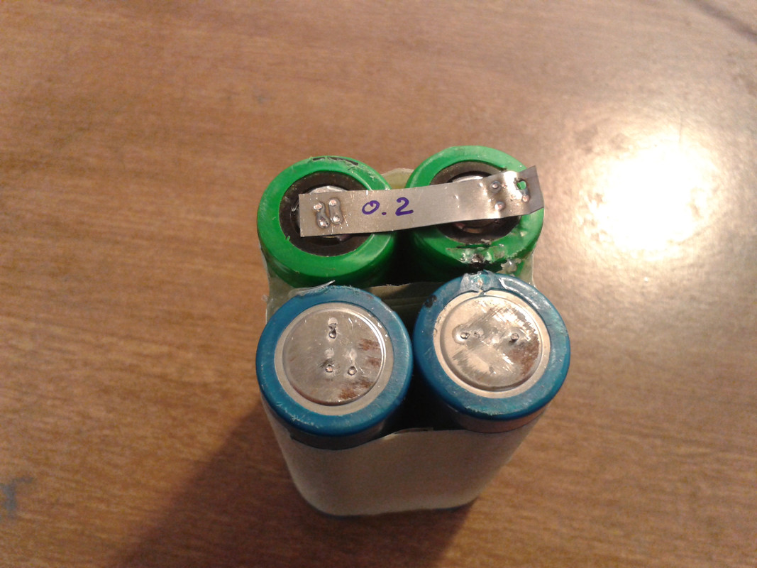
So I tried to reduce the input cables resistance and I obtained a cleaner pair of spots (nickel strip 0.2mm thickness) with the following setup: Input Batt: 8V; Energy set 55J and the results where PW=12.78ms Current=1405A.
After calibration I obtain values between 1.2mOhm and 1.4mOhm
Now I'm trying the first battery setup with a LiPo 3S5P but I have added some resistance in the input cables by adding 200mm of 10AWG cables on both positive and negative than I will reduce the length of the input cables to see what I can obtain at 12V.
The first results are the following:
Input Batt: 12V; Energy set 55J and the results where PW=40ms Current=1358A with a bad pair of spots not clean (nickel strip 0.2mm thickness)
These days I changed some settings and I tried to vary the resistance of the input cables and the input voltage.
My target is to obtain the lower pulse width with the higher current to have a nice clean spot.
At the beginning to solve the over current problem I reduced the voltage of my LiPo input battery from 12V to 8V but now I noticed that at 8V I have a fairly low current at about 1200A with a pulse width of 35ms with a 50J energy (nickel strip 0.2mm thickness). This result in a spot not clean but with a black/blue contour because the longer the pulse width the higher the heat generated between the two spots.
So I tried to reduce the input cables resistance and I obtained a cleaner pair of spots (nickel strip 0.2mm thickness) with the following setup: Input Batt: 8V; Energy set 55J and the results where PW=12.78ms Current=1405A.
After calibration I obtain values between 1.2mOhm and 1.4mOhm
Now I'm trying the first battery setup with a LiPo 3S5P but I have added some resistance in the input cables by adding 200mm of 10AWG cables on both positive and negative than I will reduce the length of the input cables to see what I can obtain at 12V.
The first results are the following:
Input Batt: 12V; Energy set 55J and the results where PW=40ms Current=1358A with a bad pair of spots not clean (nickel strip 0.2mm thickness)
parabellum
1 MW
Adding cable length can be the wrong way to go as you ad inductance and stress on the electronics. Shortening weld pulses by lowering J value may have better results on reliability.bigbore said:I have added some resistance in the input cables by adding 200mm of 10AWG cables on both positive and negative
parabellum said:Adding cable length can be the wrong way to go as you ad inductance and stress on the electronics. Shortening weld pulses by lowering J value may have better results on reliability.bigbore said:I have added some resistance in the input cables by adding 200mm of 10AWG cables on both positive and negative
May be but I want to go up with the current at the same amount of energy. Lowering the energy results in a bad/weak spot weld.
parabellum
1 MW
I may be wrong but, kWeld does not limit the current, it adjusts the pulse length on Joule basis. Your only current limiting factor is circuit resistance. Lowering circuit resistance, like shortening cables, increasing cross-section, increasing surface contact on electrodes without any change in settings will increase current and by algorithm lower the pulse lengthbigbore said:May be but I want to go up with the current at the same amount of energy. Lowering the energy results in a bad/weak spot weld.
parabellum said:I may be wrong but, kWeld does not limit the current, it adjusts the pulse length on Joule basis. Your only current limiting factor is circuit resistance. Lowering circuit resistance, like shortening cables, increasing cross-section, increasing surface contact on electrodes without any change in settings will increase current and by algorithm lower the pulse lengthbigbore said:May be but I want to go up with the current at the same amount of energy. Lowering the energy results in a bad/weak spot weld.
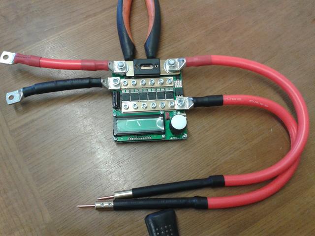
Sure it works that way so I started with these huge 4AWG cables:
And this 3S5P lipo made with very old zippy lipo 5000mAh 40C cells:
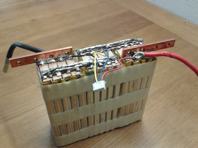
And I could not do anything because Kweld tripped the over current protection while attempting the first calibration. So following the advice of the builder I reduced the input battery at 2S5P ad finally succeeded to have a calibration done with a R=1.24 mR. Note that I also changed the input cables to 8AWG because I do not have the copper bar on the second negative contact of my welding battery.
This is what I have that produce the colored black/blue spot welds due to too many long pulse width as described above.
Two days ago I decided to dial the welder in a better way because 280 new VTC6 cells are on the way to my home and I will be spot welding a new battery shortly.
Again following the advice of the builder I tried to reduce the cable resistance staying at 8V (2S5P) and for the moment with the positive input cable back to 4AWG I obtained the best result so far. A cleaner pair of spots (nickel strip 0.2mm thickness) with the following setup: Input Batt: 8V; Energy set 55J and the results where PW=12.78ms Current=1405A.
Note that with this setup I trip the over current if I try the calibration.

I would like to reach a current around 1800A - 1900A with a pulse width of about 10-15ms so for the moment I tried to go back at 12V with the idea of shortening the 10AWG cables a little at a time (which I added) to see if I have an increase in current during welding but may be I will try again 8V with also the negative cable back to 4AWG.
I wonder if anybody else with Kweld obtained spot welds with current around 2kA?
parabellum
1 MW
OMG  You really are seriously in it!
I suppose, over current protection feature is codded in to the IC algorithm to protect Fets and not a discrete hardware solution.
Can't tatus just remove it or raise the bar a little, just in your welder, for experimenting purposes?
I suppose, over current protection feature is codded in to the IC algorithm to protect Fets and not a discrete hardware solution.
Can't tatus just remove it or raise the bar a little, just in your welder, for experimenting purposes?
My thoughts to this are that this is a kind of optimization task:bigbore said:I'd like to see what results other users of this welding machine get with the various parameters that can be set.
These days I changed some settings and I tried to vary the resistance of the input cables and the input voltage.
My target is to obtain the lower pulse width with the higher current to have a nice clean spot.
At the beginning to solve the over current problem I reduced the voltage of my LiPo input battery from 12V to 8V but now I noticed that at 8V I have a fairly low current at about 1200A with a pulse width of 35ms with a 50J energy (nickel strip 0.2mm thickness). This result in a spot not clean but with a black/blue contour because the longer the pulse width the higher the heat generated between the two spots.
So I tried to reduce the input cables resistance and I obtained a cleaner pair of spots (nickel strip 0.2mm thickness) with the following setup: Input Batt: 8V; Energy set 55J and the results where PW=12.78ms Current=1405A.
After calibration I obtain values between 1.2mOhm and 1.4mOhm
Now I'm trying the first battery setup with a LiPo 3S5P but I have added some resistance in the input cables by adding 200mm of 10AWG cables on both positive and negative than I will reduce the length of the input cables to see what I can obtain at 12V.
The first results are the following:
Input Batt: 12V; Energy set 55J and the results where PW=40ms Current=1358A with a bad pair of spots not clean (nickel strip 0.2mm thickness)
a) the current must stay below 2kA during calibration (with zero Ohms spot resistance)
b) the current should not drop too much when the weld spot resistance is added to the total resistance (typical values of that are 1-2 mOhm)
c) total wiring length must be as short as possible to minimize inductive kickback
d) wire cross section should be as large as possible to minimize losses
There are a number of contradictions in this (this list is probably not complete):
- to achieve a) we need to use a low battery voltage and/or thinner wires
- we can't easily extend the wire length to addr resistance because of c)
- to achieve b) we need to use a high battery voltage, which minimizes the current drop caused by this additional resistance
- a high battery voltage will again increase the current, endangering a)
- we can't easily increase the wire cross section to achieve d), because this again endangers a)
My solution to this optimization problem was the Turnigy nanotech 3S/5AH/130C, plus 1 meter of 8AWG wires. The typical welding current is around 1400A, and calibration does not exceed 2000A. I am paying a price for this, which is that the system efficiency (amount of energy delivered into the weld versus drawn energy) is only 15%.
You need a certain Joule value to make a good weld, just lowereing this doesn't help. But you are right, extending the cable length doesn't help well because kWeld then also lowers the overcurrent limit to protect itself from the increased amount of stored inductive energy.parabellum said:Adding cable length can be the wrong way to go as you ad inductance and stress on the electronics. Shortening weld pulses by lowering J value may have better results on reliability.
Exactly, the pulse should be a short as possible, which means the current should be as high as possible. If the pulse is too long, then heat can spread out too much. You want it to be concentrated in that tiny spot.bigbore said:May be but I want to go up with the current at the same amount of energy. Lowering the energy results in a bad/weak spot weld.
You aren't.parabellum said:I may be wrong but, kWeld does not limit the current, it adjusts the pulse length on Joule basis. Your only current limiting factor is circuit resistance.
Maybe you can use a trick here. As I described above, calibration current is always higher than welding current, because the weld spot resistance is missing. You can do the calibration with a weaker power source that delivers 1000-1500A. The machine only measures its output resistance, and it just needs enough current for that. Once you have done that, you can crank up your source.bigbore said:Note that with this setup I trip the over current if I try the calibration.
Yes, this is a software feature. I could disable that, but that will likely end up in a smokey and expensive experiment. I have actually done this experiment, and achieved roughly 100 pulses at 2800A before breakdown. As ohmic losses (and also magnetically stored energy levels) are in a quadratic equation of the current, this means that I have been using the machine at twice it's ratings. Interestingly, one of the MOSFETs failed, and the TVS diodes were still intact.parabellum said:OMG
I suppose, over current protection feature is codded in to the IC algorithm to protect Fets and not a discrete hardware solution.
Can't tatus just remove it or raise the bar a little, just in your welder, for experimenting purposes?
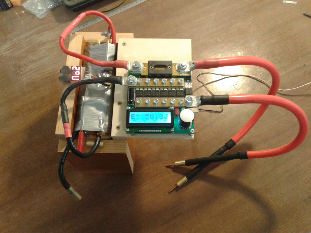
During week end I keep plying with the bigger battery option (12V) that is 3S5P shortening the 10AWG wires that I used as a resistance in the input cables.
It turns out that 30mm is the best solution to have some nice and strong spots.
These are the "resistance" I'm going to use:
The total cable lenght including copper electrodes is 1,28 meters and with this setup I was able to lower the energy needed to weld 0.2mm nickel from 50J to 30J. This is one result I noted down, but it is rapresentative for the average results. PW = 13.98ms at 1527A with 27.5J, during the many weld test I made I obtained currents from 1530A to 1560A.
bigbore said:During week end I keep plying with the bigger battery option (12V) that is 3S5P shortening the 10AWG wires that I used as a resistance in the input cables.
It turns out that 30mm is the best solution to have some nice and strong spots.
These are the "resistance" I'm going to use:
The total cable lenght including copper electrodes is 1,28 meters and with this setup I was able to lower the energy needed to weld 0.2mm nickel from 50J to 30J. This is one result I noted down, but it is rapresentative for the average results. PW = 13.98ms at 1527A with 27.5J, during the many weld test I made I obtained currents from 1530A to 1560A.
Great job adapting to the higher power.
Thanks for sharing.
I have changed the design because the existing system is heating up too quickly, the replacement electrodes are too costly and too complex, the handle is too short for ergonomic use, crimping brass is tricky. The new ones are much longer (70mm) and much heavier for better heat dissipation. The C14500 copper is needed for CNC machineability, but I expect this also to improve electrode lifetime.Alcus said:I see the new C14500 (tellurium copper) CNC’ed electrode system in your shop.
Looks very interesting. Can't wait to get more details on that.
Do you expect that this will perform better when spot welding thin copper wires?
I haven't made own experiments with fuse wire welding, but several customers are doing this and have reported me that this is working well. One customer will be testing thin flat tungsten electrodes though, as this is supposedly the best method here. One of the advantages of kWeld is that it is very fast: the minimum pulse duration is 40 microseconds, and increments are 10 microseconds.
Do you know what kind of wire they were using for fuse wires?
I have asked one of them a few days ago, I will post when he has responded.fechter said:Do you know what kind of wire they were using for fuse wires?
I have just finished the laser-cut housing for the capacitor module and ordered a few copies. If someone is interested, I have put them in the shop here:
https://www.keenlab.de/index.php/product/kcap-laser-cut-housing-kit/
The DXF files are available here for download:
https://www.keenlab.de/index.php/product/kcap-laser-cut-housing-dxf-model/
I'm becoming a fan of acrylic sheet material laser-cutting, this design works without glueing a single piece :wink:
tatus1969 said:I have asked one of them a few days ago, I will post when he has responded.fechter said:Do you know what kind of wire they were using for fuse wires?
I'm becoming a fan of acrylic sheet material laser-cutting, this design works without glueing a single piece :wink:
Thin wire - Until that person answers, here are my two cents:
I strip good quality silicone wire such as what is supplied with kWeld to get +-40AWG thinned copper wire. A length of 8AWG should yield about 1650 strands, 16AWG 252 strands, 30AWG 11 strands, etc.
I'm expecting that should fuse somewhere around 1.5A within about 1 second. Still to be tested!
I hope to use multiple strands on the same cell for increased amperage. Still to be tested.
I also get +-30AWG thinned copper wire from cheap "silicone wire". That is a silicone sheath but the cable is substandard and nowhere as flexible. I'm expecting that should fuse within a second somewhere around 15A. Still to be tested!
Those two gauges should meet all my needs but I am still looking for other gauges. I have only located non thinned copper and enamelled copper wire for sale by the spool so I strip
Once I get my two kCaps, I'll have the power and will be running some tests on these thin copper wires. If anyone has already done this, please feel welcome to share your settings and tips.
If kWeld does not work out with these copper wires, I plan to test using pure nickel wire. Again, if anyone has already done this, please feel welcome to share.
Enclosure - No glue sounds like a nice convenient improvement. Thanks Frank for the improved design. I look forward to assembling that. I did not have any trouble with the kWeld enclosure but no glue sounds like a better and faster way to get to the fun stuff
Hope you are enjoying the weekend and getting some rest!
A
Are you saying that you plan to put two kCap in parallel for enough current to weld fuse wires? Is that to make the pulse duration as short as possible in order to concentrate the energy?Alcus said:Once I get my two kCaps, I'll have the power and will be running some tests on these thin copper wires. If anyone has already done this, please feel welcome to share your settings and tips.
If kWeld does not work out with these copper wires, I plan to test using pure nickel wire. Again, if anyone has already done this, please feel welcome to share.
We've started shipping kCap modules and enclosures today, here's a first impression of how that assembly looks:

p.s. no update from that customer yet. But I won't insist, I don't want to annoy my customers.
Similar threads
- Replies
- 0
- Views
- 480
- Replies
- 8
- Views
- 509
- Replies
- 23
- Views
- 2,206
- Replies
- 1
- Views
- 519