TSDZ2 mid drive with 860C, 850C or SW102 displays only -- Flexible OpenSource firmware (Casainho code only)

jeanl said:
casainho said:
The original firmware runs the motor very silently compared to the 6 steps/square wave/block commutation I implemented. I saw the PWM signals and are SVM just like used on FOC but I think they are simple doing "FOC" using motor parameters!!
The development is blocked because I don't know how to implement "FOC" using the motor parameters... Let's see if jur can help ;)
casainho, I have no specific knowledge of FOC, but I have Electrical Engineering background with lots of math etc, so perhaps I can help with that. I need to have a bit more background though. I perused through the document that was posted above (the lengthy one with all the details on FOC) but I need to read it a lot more carefully if I want to help.
What do you mean by " I don't know how to implement "FOC" using the motor parameters"? Can you quickly summarize where you are and what you think is missing?
Jean
(and kudos for all you're doing, it's awesome)
Same here, electrical engineer in field of power electronics. Power conversion is my bread and butter but I haven't done any motor control so have to learn the stuff from scratch.

BUT @casainho, if your only problem is that floating point math is taking too long, it isn't a problem to use integer math in this case. Our company does digital control of power converters, and floating point isn't used - we simply use integer math and convert at the end. Enough bits and accuracy is not impacted.

For example, duty cycle can be encoded with sufficient resolution using 8 bits (more than enough or even too many, 7 may be enough even with good enough resolution for this application). Voltage, also 7 or 8 bits. To get E, multiply, then right shift keeping the correct MSB. And so on. I am assuming you can do 16 bit operations.

Another question, what PWM frequency are you aiming for? Several issues here: Too high won't work, probably causing magnetising losses in the stator core, and the MOSFET gate drives are also very slow, from a TSDZ2 circuit I saw somewhere. I would measure the existing firmware's frequency and aim for the same, at least as a starting point.
 
Another item, do we have the motor parameters yet? I have extremely accurate and sensitive inductance and resistance measuring instrumentation at work; but I don't want to take apart my wife's freshly-built bike again if I can avoid it.
 
jur said:
Another item, do we have the motor parameters yet? I have extremely accurate and sensitive inductance and resistance measuring instrumentation at work; but I don't want to take apart my wife's freshly-built bike again if I can avoid it.
No, we don't have. And yes, hard to get that parameters. Really great if you can do it.

I expect to receive some donated controllers that I will use to see the board from the backside - I don't want nothing to be missing, I need to make sure the we already know every input and output signals.
 
casainho said:
fantasy2 said:
Just registered here after googling around for this motor. Awesome work everyone here is doing!

I'm wondering if you run the engine in the bike with original firmware and modified firmware if the sound/noise level is still the same? It's the thing that's been bothering me. If it's the same, then there is an opportunity to reduce it. If I see it right then this motor is brushless DC as well. With more complex algorithms, these motors can run more smooth and quiet.

If I find time between my other projects and work I'm happy to assist. I'm very familiar with Atmel and ARM(STM) coding and hardware development.
The original firmware runs the motor very silently compared to the 6 steps/square wave/block commutation I implemented. I saw the PWM signals and are SVM just like used on FOC but I think they are simple doing "FOC" using motor parameters!!

The development is blocked because I don't know how to implement "FOC" using the motor parameters... Let's see if jur can help ;)

Please find free time -- if you believe in electric bicycles, improving the environment, improving people's wealth life, on this project your work will have a widder impact simple because TSDZ2 is very popular!! A lot of activity on this forum thanks to it!!

STM8 is very near STM32, the same datasheet types, almost same development tools, the same peripherals, etc. Will be easy for you.
I once evaluated the STM8S105 for a project but went for an atmel instead(they are still pretty good compared to other chips on MIPS level), I guess it wouldn't be too hard.

On another thread I read that there were some doubts if this 8 bitter could implement a good and fast FOC. I haven't looked at the electronics but I'm wondering if it would be interesting to redesign the controller so it has a bit more juice. Like STM32F1/2/4. It allows for more heavy and faster calculations.

Anyway, I first have to buy a unit.. No reseller here so I have to google around on aliexpress to find a decent one(I'm looking for the 500/750Watt version with XH18 display).
 
fantasy2 said:
On another thread I read that there were some doubts if this 8 bitter could implement a good and fast FOC. I haven't looked at the electronics but I'm wondering if it would be interesting to redesign the controller so it has a bit more juice. Like STM32F1/2/4. It allows for more heavy and faster calculations.
No, STM8 can't handle "traditional" FOC.

This project is not about design a controller but instead develop the firmware (the best, hopefully) for original motor controller. I was on another projects before were I dreamed with the idea of replacing the controller and found almost no one will want to mess with prototyping hardware and hardware is also a lot expensive to develop -- firmware/software on the other side is cheap and more people can join the project and develop, because the tools for development are cheap, unlike developing hardware.
 
jur said:
BUT @casainho, if your only problem is that floating point math is taking too long, it isn't a problem to use integer math in this case. Our company does digital control of power converters, and floating point isn't used - we simply use integer math and convert at the end. Enough bits and accuracy is not impacted.

For example, duty cycle can be encoded with sufficient resolution using 8 bits (more than enough or even too many, 7 may be enough even with good enough resolution for this application). Voltage, also 7 or 8 bits. To get E, multiply, then right shift keeping the correct MSB. And so on. I am assuming you can do 16 bit operations.
Thanks for the info. For now, I think that even with float operations, for the measured times on my experiences, it should work. Optimizations can come later.

jur said:
Another question, what PWM frequency are you aiming for? Several issues here: Too high won't work, probably causing magnetising losses in the stator core, and the MOSFET gate drives are also very slow, from a TSDZ2 circuit I saw somewhere. I would measure the existing firmware's frequency and aim for the same, at least as a starting point.
PWM frequency from original firmware is 16kHz -- I was expecting more thinking that mosfet driver IC would for improving the frequency.

So motors runs at 4000 RPM, that is near of the 520 ERPS limit we are using on our firmware for Kunteng, in a way SVM wave is draw with
at least 30 points.
 
Alright, I'll stop dreaming. Let's see how far we can push this thing first. Some assembly and integer math can be pretty efficient(floats are extremely dirty in my eyes on an 8 bitter).

I hope to receive my TSDZ2 soon so I can join the development and testing.
 
fantasy2 said:
I hope to receive my TSDZ2 soon so I can join the development and testing.
Everyone please see here a list of development tools: https://opensourceebikefirmware.bitbucket.io/INSTALL_FIRMWARE.html

Please ignore that of soldering the programming header as TSDZ2 cable already has the needed wires.
 
casainho said:
Thanks for the info. For now, I think that even with float operations, for the measured times on my experiences, it should work. Optimizations can come later.
Could you please state exactly what you need for solving the math:

Inputs, equations to solve and required outputs. I am deep into generating the simplest possible math operations but it would be most efficient if you could please spec what you need.
 
jur said:
casainho said:
Thanks for the info. For now, I think that even with float operations, for the measured times on my experiences, it should work. Optimizations can come later.
Could you please state exactly what you need for solving the math:

Inputs, equations to solve and required outputs. I am deep into generating the simplest possible math operations but it would be most efficient if you could please spec what you need.
Looking at the documentation from Shane Colton here:
- https://opensourceebikefirmware.bitbucket.io/development/Motor_control--FOC--Shane_Colton_documentation_and_firmware.html
- https://github.com/EGG-electric-unicycle/documentation/blob/master/Shane_Colton/3phduo.pdf

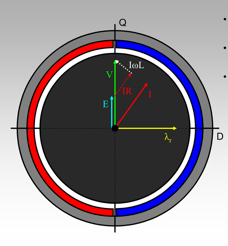
1. Without align current with BEMF (inefficient controlling of the motor)
image.png


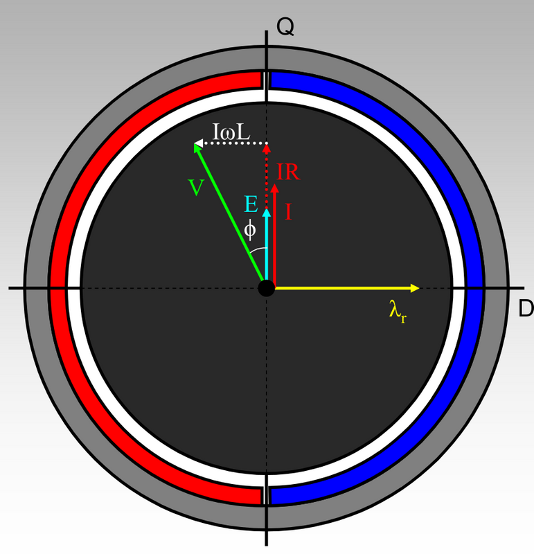
2. Aligning current with BEMF (efficient controlling of the motor)
image.png


I know that we want to be at 2.

I think as inputs we have:
- direction of Q axis, as we can measure BEMF by rotating the motor with our hands and BEMF direction is max value of the sinewave measured and then we can reference to hall sensors transition signals
- we don't know phi r (yellow vector) and I think we don't need it. It just represents north pole of one magnet of rotor
- I we can measure. I is the phase current however we just can measure battery current on the shunt and I phase current = I battery current * actual PWM duty_cycle.
- IR is I * motor coil resistance, that is why we need to measure the resistance
- E is the BEMF, which is motor constant of generated volts per RPM, and it can be measured but we know for our motors can be something near as 36V(48V) / 4000 RPM. Knowing the motor speed, that we can measure using hall sensors signals, we can calculate the E
-- phi r (yellow vector) is equal to BEMF
- IwL can be calculated knowing the I, motor speed and L motor inductance, that is why we need to measure the coils motor inductance
- V is the phase voltage we apply to the motor phases, and it is Vbattery that we can measure * currently PWM duty_cycle that we apply

As we can see angle teta increases with IwL and IR, so, depends from motor speed and current. We can measure both and we know that angle between IR and IwL are always 90 degrees. How can we calculate the angle on 1. so we can advance the phase voltage V by that angle value and I will be in aligned with E an so we will get the higher torque per amp??

On the second link for documentation of Shane Colton, he talks about some math to calculate the angle:
file.php

Please look at this message of Stancecoke: https://endless-sphere.com/forums/viewtopic.php?f=30&t=93818&start=50#p1375474

And please note that we don't need the angle value, we may just need to know if the angle is positive, negative or near zero. On Kunteng controller, in our firmware, we just do that and it works very well!! See here a resume: https://opensourceebikefirmware.bitbucket.io/development/Datasheets_and_application_notes--Endless-sphere.com_forum_messages--2017.10.23_-_FOC_and_no_FOC_comparison.html

This is all the I know for now. And the PWM signal on TSDZ2 motor controller is just the same as on Kunteng, that we already implemented and works very well. On TSDZ2, there is no phase current sensor and I think it is not needed because it just need to work with a specific motor with a know R and L values unlike on Kunteng that should work with most hub and even mid driver motors -- for instance, the PWM frequency on Kunteng is just the same 16kHz.
 
casainho said:
jur said:
Could you please state exactly what you need for solving the math:

Inputs, equations to solve and required outputs. I am deep into generating the simplest possible math operations but it would be most efficient if you could please spec what you need.
Looking at the documentation from Shane Colton here:
- https://opensourceebikefirmware.bitbucket.io/development/Motor_control--FOC--Shane_Colton_documentation_and_firmware.html
- https://github.com/EGG-electric-unicycle/documentation/blob/master/Shane_Colton/3phduo.pdf

1. Without align current with BEMF (inefficient controlling of the motor)
image.png


2. Aligning current with BEMF (efficient controlling of the motor)
image.png


I know that we want to be at 2.

I think as inputs we have:
- direction of Q axis, as we can measure BEMF by rotating the motor with our hands and BEMF direction is max value of the sinewave measured and then we can reference to hall sensors transition signals
- we don't know phi r (yellow vector) and I think we don't need it. It just represents north pole of one magnet of rotor
- I we can measure. I is the phase current however we just can measure battery current on the shunt and I phase current = I battery current * actual PWM duty_cycle.
- IR is I * motor coil resistance, that is why we need to measure the resistance
- E is the BEMF, which is motor constant of generated volts per RPM, and it can be measured but we know for our motors can be something near as 36V(48V) / 4000 RPM. Knowing the motor speed, that we can measure using hall sensors signals, we can calculate the E
-- phi r (yellow vector) is equal to BEMF
- IwL can be calculated knowing the I, motor speed and L motor inductance, that is why we need to measure the coils motor inductance
- V is the phase voltage we apply to the motor phases, and it is Vbattery that we can measure * currently PWM duty_cycle that we apply

As we can see angle teta increases with IwL and IR, so, depends from motor speed and current. We can measure both and we know that angle between IR and IwL are always 90 degrees. How can we calculate the angle on 1. so we can advance the phase voltage V by that angle value and I will be in aligned with E an so we will get the higher torque per amp??

On the second link for documentation of Shane Colton, he talks about some math to calculate the angle:
file.php

Please look at this message of Stancecoke: https://endless-sphere.com/forums/viewtopic.php?f=30&t=93818&start=50#p1375474

And please note that we don't need the angle value, we may just need to know if the angle is positive, negative or near zero. On Kunteng controller, in our firmware, we just do that and it works very well!! See here a resume: https://opensourceebikefirmware.bitbucket.io/development/Datasheets_and_application_notes--Endless-sphere.com_forum_messages--2017.10.23_-_FOC_and_no_FOC_comparison.html

This is all the I know for now. And the PWM signal on TSDZ2 motor controller is just the same as on Kunteng, that we already implemented and works very well. On TSDZ2, there is no phase current sensor and I think it is not needed because it just need to work with a specific motor with a know R and L values unlike on Kunteng that should work with most hub and even mid driver motors -- for instance, the PWM frequency on Kunteng is just the same 16kHz.
Thanks for the clarification. Back to playing with math...
 
I am a bit confused by seemingly redundant information:

1. The needed phase angle advance called phi by Colton, will always be of the same sign. Current will always lag voltage, no sign is needed.
2. The sine of the phase advance angle phi can be calculated by
sinphi = IwL/V; where we measure and calc I, w is measured by Hall sensor, L is a constant, and V is also measured, right? I thought V is an output of the control scheme, driven by torque sensor demand?
3. The cosine of phi can be calculated by
cosphi = (E+IR)/V
4. The tangent is given by
tanphi = IwL/(E+IR)

It seems to me redundant to need both R and L. If we have V, sinphi can be calculated without needing R.

Of course if we don't have V, the we need to calculate the tangent.

So the big question is, do we have V? I think not since it is an output of the algorithm. The magnitude and phase are the outputs.

HOWEVER: We can estimate V by using the previous fast loop's value! It will be out by a small amount but that may be OK. So, my suggestion for a starting point is to calculate the sinphi according to point 2 above and plug that straight into the control algorithm.
 
jur said:
I am a bit confused by seemingly redundant information:

1. The needed phase angle advance called phi by Colton, will always be of the same sign. Current will always lag voltage, no sign is needed.
2. The sine of the phase advance angle phi can be calculated by
sinphi = IwL/V; where we measure and calc I, w is measured by Hall sensor, L is a constant, and V is also measured, right? I thought V is an output of the control scheme, driven by torque sensor demand?
3. The cosine of phi can be calculated by
cosphi = (E+IR)/V
4. The tangent is given by
tanphi = IwL/(E+IR)

It seems to me redundant to need both R and L. If we have V, sinphi can be calculated without needing R.

Of course if we don't have V, the we need to calculate the tangent.

So the big question is, do we have V? I think not since it is an output of the algorithm. The magnitude and phase are the outputs.

HOWEVER: We can estimate V by using the previous fast loop's value! It will be out by a small amount but that may be OK. So, my suggestion for a starting point is to calculate the sinphi according to point 2 above and plug that straight into the control algorithm.

1. Not sure, what if we advance to much the phase voltage??

Yes, I think V is the value we apply to motor phases.

Do you think that calculating the angle like you suggest will also apply to image 1. Or just to 2.???
 
casainho said:
1. Not sure, what if we advance to much the phase voltage??
If we advance a little bit too much, the calculation will still come out positive because we use magnitude values for I and V. For the next fast loop cycle the value of phi is re-calculated so it will be self-correcting.
casainho said:
Yes, I think V is the value we apply to motor phases.
So we can just use the previous fast loop value as it won't change much between fast loop cycles. Or, as a refinement the value can be calc'ed.
casainho said:
Do you think that calculating the angle like you suggest will also apply to image 1. Or just to 2.???
I was looking at #2. The phase angle advance will be iteratively corrected with each successive fast loop cycle. As a phase advance is applied to V, the current will change somewhat, affecting the next calculation, and so on until the error is zero. But as far as I can see, the error will start small anyway.
 
Tomorrow I will try to see if I can remove the covers without taking the motor off the bike, in order to measure motor winding R and L.
 
jur said:
Tomorrow I will try to see if I can remove the covers without taking the motor off the bike, in order to measure motor winding R and L.
Good!! I think you need at least to remove left cover and that means removing the left pedal crank to be able to remove the cover.
 
Got a 48V motor and 48V controller and finally were able to drive my ebike with TSDZ2!! Really good, now I understand why they are so popular!!

The cables of the controller couldn't be inserted on the original hole because of the sockets so I quick and dirty did a hole -- the metal is very soft.

The LCD has the symbol watts, we can see that when we turn on the display, but the LCD can't show the watts of the motor. Don't even show the voltage of the battery... LCD3 is much better!!

Did run both 36V and 48V motors with the same 36V controller to see if I got a different sound but both did run silent -- but they were without load, maybe that is why even if they are different, there should no be much different on the algorithm.

 
casainho said:
jur said:
Tomorrow I will try to see if I can remove the covers without taking the motor off the bike, in order to measure motor winding R and L.
Good!! I think you need at least to remove left cover and that means removing the left pedal crank to be able to remove the cover.
Unfortunately I didn't look at it before coming to work today, so now I don't have the necessary tools with me - I assumed that the cover could be taken off without taking the crank arm off.

So I will take our small hand-held meter home tonight and do the measurements tonight. It is also quite accurate. Why I didn't think of this yesterday, I don't know. Senior moment I suppose.

Is there a rough estimate for motor L that will allow you to move forward? For example, is the Kunteng motor L known?
 
jur said:
Is there a rough estimate for motor L that will allow you to move forward? For example, is the Kunteng motor L known?
No and I never saw values for L on chinese ebike motors.

Right now I am looking to improve the current motor control code for Kunteng, are there some piece of code works but I think with some luck. I need to improve it and validate, so I can learn it better and then I will use for TSDZ2. The code should be almost the same...
 
jur said:
casainho said:
1. Not sure, what if we advance to much the phase voltage??
If we advance a little bit too much, the calculation will still come out positive because we use magnitude values for I and V. For the next fast loop cycle the value of phi is re-calculated so it will be self-correcting.
Can you think in a way that we can go even quick and dirty, like knowing if we simple are near our target or if we are on right or left side. If on left, we just increase by a step, on right decrease a step and near the target just keep current angle value. That is how it works on Kunteng...
 
casainho said:
jur said:
casainho said:
1. Not sure, what if we advance to much the phase voltage??
If we advance a little bit too much, the calculation will still come out positive because we use magnitude values for I and V. For the next fast loop cycle the value of phi is re-calculated so it will be self-correcting.
Can you think in a way that we can go even quick and dirty, like knowing if we simple are near our target or if we are on right or left side. If on left, we just increase by a step, on right decrease a step and near the target just keep current angle value. That is how it works on Kunteng...
Ah, I see. I will look into it.

The measured values are:
L=270uH
R=0.25ohm

This is between 2 windings. I am assuming very little or no mutual inductance, which makes the individual phase values half those values.

So,
L=135u = 0.000135
R=0.125
 
jur said:
The measured values are:
L=270uH
R=0.25ohm

This is between 2 windings. I am assuming very little or no mutual inductance, which makes the individual phase values half those values.

So,
L=135u = 0.000135
R=0.125
GREAT!!! :)

To evaluate the algorithm, I would implement:
- the angle calculation and print it to outside, then I would accelerate the motor and try put some load and see if the angle value increases as expected
- when angle is applied:
-- expecting a lower noise of the motor, at least so good as original firmware
-- with a constant PWM duty-cycle and constant load and speed (on bike training roller), adjust the angle manually up to get the lowest current - then enable the algorithm and expect the same lowest current
 
jur said:
casainho said:
jur said:
casainho said:
1. Not sure, what if we advance to much the phase voltage??
If we advance a little bit too much, the calculation will still come out positive because we use magnitude values for I and V. For the next fast loop cycle the value of phi is re-calculated so it will be self-correcting.
Can you think in a way that we can go even quick and dirty, like knowing if we simple are near our target or if we are on right or left side. If on left, we just increase by a step, on right decrease a step and near the target just keep current angle value. That is how it works on Kunteng...
Ah, I see. I will look into it.

The measured values are:
L=270uH
R=0.25ohm

This is between 2 windings. I am assuming very little or no mutual inductance, which makes the individual phase values half those values.

So,
L=135u = 0.000135
R=0.125

isn't that depended of the configuration of the motor? delta or wye
 
@jur, are that values for 48v or 36v motor?
 
Might sound crazy that I am just starting new projects with finish the others... that's why I alone can't do everything, it is really important that you guys help on this project!!

I really hope to use LCD3 with TSDZ2 as the original LCD is very limited. Why can't I see the motor power in real time? Why can't I see the battery voltage??

This is the new project: LCD3 firmware -- Flexible OpenSource firmware for Kunteng LCD3
 
Back
Top