My Sun Trip Bike, Back to Back Tandem Trike with Rowing Generator, Pedals, +Solar

Warren said:
Yes. If the foot pegs were half way up the pendulum Justin would get the 2:1 ratio he is looking for. But the shorter the pendulum for the feet, the less you approximate a linear path.


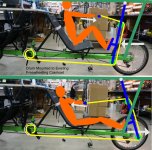
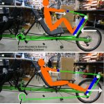
Hmm, I must have done a bad job conveying stuff in the drawing though I can see now how it looks this way! The front blue platform isn't meant to be a pivoting pendulum but rather a sliding carriage. That front section would move forwards and backwards on a set of rails but stay oriented the same way, like this:

Rowingbike Drive Concept, Better Explained.jpg

However, I kindof like the idea of using a pivot on the leg section as that's always a simper and more robust to fabricate than a sliding rail, I'd just need to see if the arc motion of the legs would be OK or not.
 
Warren said:
Thanks for clearing that up. Your understanding of both styles is correct.

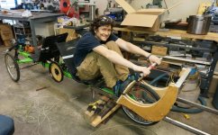
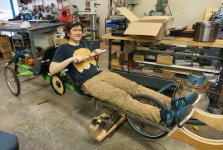
Well, after a furious couple days in the shop I got the first prototype of the rowing station based on this design fully mocked up. There is a set of 3/4" x 1.5" steel rectangular tube stock rails with a plywood carriage that rolls back and forth, with 3 castor wheels sandwiched between the plywood cutouts to keep things sorta smooth. The string itself then wraps around the a pair of pulleys and goes to the drum which I ended up making from a 16" bicycle rim.

Suntrip Reach.jpg

Suntrip Pull.jpg

The total pull on the string from this rowing motion was 68 inches. In my original planning this was going to be directly spinning a motor / generator, and so we would choose a drum diameter that would spin the motor at an RPM that would do 300 watts at the best effeciency.

Referring back to this chart that I created here:
file.php

https://endless-sphere.com/forums/viewtopic.php?p=1375674#p1375674

That optimal speed could range from 150 rpm to 500 rpm depending on the motor choice. If I want to row at 30 strokes per minute, that's a full 68 inches of string pull in a 1 second period (then another 1 second to have it rewind). For 500 rpm we would want a 2.6" drum diameter. For 150 rpm it would be a much larger but still OK 8.6" diameter. What I didn't fully appreciate in this design was just how large the drum would need to be if it's going to directly replace the tandem cranks for a mechanical linkage. Then we would want to be spinning at crank speeds of like 80 rpm. For that we're talking 16" or so drum size!

In the end I used a 16" bicycle rim (effectively 12" diameter) mounted to a piece of plywood that was cut and drilled out to fit on the chainring spider. We'll be able to tweak the sprocket size on the right side so that this corresponds to a comfortable pedaling cadence for the rider at the front. Right now a comfortable rowing rhythm is still a faster than ideal cadence.

Anyways, it works! This was from yesterday's first maiden test ride, pretty exciting to see it work out
[youtube]5v_jH8hdfdw[/youtube]
 
justin_le said:
However, I kindof like the idea of using a pivot on the leg section as that's always a simper and more robust to fabricate than a sliding rail, I'd just need to see if the arc motion of the legs would be OK or not.

After doing some more examination of this option I think it would probably the best way forwards, so Fetcher and Warren's misinterpretation of my initial sketch could actually be the way that we build it, thank you guys for the inadvertent input :mrgreen: ! Part of what makes this really work is the fact that I'll have a roof structure already in place for the solar panels, and that provides a nice high point from which to pivot the pendulum that the legs will push on, ensuring a large arc radius and fairly flat motion of the legs.

Rowingbike Pivot Drive Concept.jpg

It's going to look a tiny bit goofier than the sliding design, but has so many advantages for reliability by trading a pair of parallel sliding rails for a single pivoting structure. And it should be lighter too.

I think it's CAD modeling time to make a proper 3D mockup so that we can get to purchasing metal stock and fabrication!
 
I like the feature of having both the leg and arms working in practice it looks awkward but t might work out to have it switchable from legs to arms by removing and inserting a pin similar to how universal gyms are set.
 
eCue said:
t might work out to have it switchable from legs to arms by removing and inserting a pin similar to how universal gyms are set.

With both the designs that I've sketched you don't actually need to remove and insert a pin for this. You can easily just have the legs steady and only pull with your arms, or keep the arms locked and just push with the legs.
 
Love your work Justin.

This is so cool!

Have you tried it by youself? Might be marketable as a pedicab or ubercycle! Ha!
 
Sorry if I am being critical. My thoughts on just about everything is that easier, simpler, cheaper, and faster to buy not build. Also the end result is usually better. If I set out to build something that does not exist it usually takes 3 prototypes minimum before I get it all figured out.

Watched your rowing machine video and it caused my back to start hurting. If I was wanting to create a combination pedal/rowing bike. I would buy a pedal bike ..and.. a rowing bike and fasten them together. Here is a picture of two vehicles fastened together. A guy in Indonesia got tired of backing out of his driveway so he bought two cars, cut them in half, and welded the two front ends together.
toyota-dual-7.jpg

Yes it is fun to build stuff. Have fun building a rowing machine :D
 
justin_le said:
Rowingbike Pivot Drive Concept.jpg

It's going to look a tiny bit goofier than the sliding design, but has so many advantages for reliability by trading a pair of parallel sliding rails for a single pivoting structure. And it should be lighter too.

I think it's CAD modeling time to make a proper 3D mockup so that we can get to purchasing metal stock and fabrication!

Goofy is in the eye of the beholder. I think you have nailed it. Thank you Justin. I look forward to an electric assist, single rowbike from Grin Tech. I will buy the first one. Don't forget the PV roof on mine. :)
 
Love you work Justin! Single pivot structure from the roof is inspired and strikes me as potentially more reliable and significantly more repairable. Are you going to make the footrest portion of your diagram pivot, this would remove the small (but perhaps troublesome over a long enough period) upward roll of the foot over the stroke.
 
Ohbse said:
Love you work Justin! Single pivot structure from the roof is inspired and strikes me as potentially more reliable and significantly more repairable.

Thanks. It's funny how this idea didn't even cross my mind until seeing the responses from Warren and Fechter following this thread. I was stuck looking at other means of doing articulated links in ways that were much more complex than just a single pivot from the roof.

Are you going to make the footrest portion of your diagram pivot, this would remove the small (but perhaps troublesome over a long enough period) upward roll of the foot over the stroke.

Yes. Actually what I'll most likely do is follow the same example as used on the THYS Rowingbike and others and use clip-in SPD pedals. That allows for pulling, pushing, and pivoting in a lightweight package assuming you've got clip in shoes. You can see them in the bottom of this pic:
https://endless-sphere.com/forums/viewtopic.php?p=1362951#p1362951

There is actually a fair bit of ankle flexing that takes place in a normal fixed angle foot platform on a rowboat, since even though the platform angle stays the same relative to the bike, the lower half of the leg changes angle quite a bit as the leg crunches and then extends out. Next time on on the THYS I'll have a close look at what my feet are doing to see if they stay at a fixed angle or naturally pivot a little over the course of a stroke.
 
I'm a big fan of clipless pedals on a recumbent. A couple of threaded holes, for pedals, is much easier than footboards too.

It's funny. I had this discussion with folks on the C2 rowing forum years ago, and many were all, "No you'd be trapped upside down in the shell and drown. Then Shimano came out with clipless for rowers. :)

http://www.shimano.com/en/manufacturing/rowing.html
 
A couple more videos from last weekend:

[youtube]WjjFAsnrkZU[/youtube]

[youtube]Hz_xe4kgU4g[/youtube]

Much more detailed update on where things are at now coming soon!
 
Haha! Watching your test ride video is so wild! That is definitely the most unique design I've ever seen. Great work so far Justin. I'm really enjoying following your progress.
 
Great work and clever mechanism.
 
I'm kind of curious about the pulsing assistance sensation for the captain when the stoker (stroker?) applies power strokes... This almost seems like it would tend to move the captain in and out of the easy cadence for the selected gear which might detract from the efficiency of his contribution. This a different situation than two pedallers or two synchronized rowers where the load is more constant or well-behaved.

This seems one of those 'gotta try it' questions and I'm wondering if you've been able to make a long enough test ride to get a sense of this.
 
teklektik said:
This almost seems like it would tend to move the captain in and out of the easy cadence for the selected gear which might detract from the efficiency of his contribution.
At speed the cadence shouldn't change much (i.e. a single stroke isn't going to significantly change the speed once they are at cruising speed.)
 
TO reduce the pulse you could use the legs as the first push on its own cable followed by a quick arm pull on its own cable / gear repeated quickly so one is resetting while the other is pushing a power stroke. For a similar effect as a hand powered railway cart making power on both strokes
 
johnrobholmes said:
Hey, those axles look familiar!

Yessir. Not many people know but John Holmes here did all the machining work on our first Pilot run of Grin motor axles. Unlike us he had a nice CNC lathe and it was great to work with someone local-ish who understood the application! They turned out great, so thanks again for that. And yes it's also from this batch that I grabbed the the motor axles for this sun trip build are coming from.

After machining them down and notching the sleeve the fit was spot on for the rotor to align with the caliper OK.

Disk Fit Test.jpg

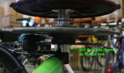
I sent out both the modded axle and extension tube for anodizing over a week ago and I'm anxious to get them back in order to build up the two motors and get on with the electrification! The tube will simply be drilled and bolted trike both to lock the motor axle against rotation and to hold the wheel in place from sliding off. Normally the front wheels were held on with a threaded bolt on the end of the hollow axle, but I'll have the electrical cable running through this area.
 
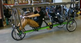
So here we are proof of concept build #2. No more sliding rig, instead it's a pivoting pendulum structure from a frame that will also support the solar roof. We finished this on Saturday afternoon, went for a spin, did more tweaking, and in a nutshell, excellent.
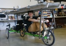
2nd Mockup.jpg

2nd Mockup, left side.jpg

We got some footage for another video blog update that we'll get ready soon.

But what we didn't get was an evening trip that Me and Anne-Sophie took riding/rowing through a popular strip in Vancouver. The response from people on the street seeing a vehicle like this is just electric. From the backwards facing rowing rig you get to see everyone's faces, comments, waves, cheers, camera shots etc. as you pass by. I'm used to some of that riding a unicycle, more so on the Penny Farthing, but this was in a totally different league, and facing backwards you get to see and interact with it.

teklektik said:
I'm kind of curious about the pulsing assistance sensation for the captain when the stoker (stroker?) applies power strokes... This almost seems like it would tend to move the captain in and out of the easy cadence for the selected gear which might detract from the efficiency of his contribution. This a different situation than two pedallers or two synchronized rowers where the load is more constant or well-behaved.

This seems one of those 'gotta try it' questions and I'm wondering if you've been able to make a long enough test ride to get a sense of this.

Very spot on observation. I haven't yet ridden on the front to experience this, but Anne-Sophie sure mentioned it on our Saturday evening promenade. On the slower uphill portions it was prominent, much less so on the flats and downhill even though I was rowing just as hard.

That's probably because a given amount of energy corresponds to a much lower change in velocity at high speeds than lower speeds, given the E=1/2mV^2 relationship. I estimate rowing modestly that each pull stroke is 300 joules. Ballpark total vehicle weight is 200 kg. Here's the change in speed we'd expect from a 300 joule energy impulse:

Code:
Initial Speed   Delta Speed from 300J
5 kph           + 3.0 kph
10 kph          + 1.8 kph
15 kph          + 1.2 kph
20 kph          + 0.95 kph
30 kph          + 0.64 kph
40 kph          + 0.48 kph

Now that's if all the energy went in as a single impulse and then nothing for 2 seconds. Since it's spread out over a 50% duty cycle, it would be to first order about half this much for the velocity change. Still quite noticeable for the captain at low speeds. But once we have the electric motors on and are generally cruising >20 kph then my expectation is that that this will be imperceptible.

If not, then I'd likely explore using a constant speed feedback loop on the CA3 and use the motor to dynamically smooth this out, exactly as demonstrated in this post:
https://endless-sphere.com/forums/viewtopic.php?p=1367643#p1367643
 
That was my last contract project before the lathe was sold. Sometimes I miss it, but such a capable machine came with an equally impressive payment (and workload) that I don't miss at all :lol: It's nice to have more free time for having fun instead of running two full time jobs, which is why I'm here again :D


Looking like quite the cool project!! Love the roof!!
 
johnrobholmes said:
Love the roof!!
+1
Though I'm thinking a generous application of a big hole saw to the fore/aft beams would cut down on the side windage which will apply force kind high up - not that the vehicle is really maelstrom-approved anyway... (or it that a mockup before the real shippable solar stuff appears?)
 
teklektik said:
johnrobholmes said:
Love the roof!!
+1
Though I'm thinking a generous application of a big hole saw to the fore/aft beams would cut down on the side windage which will apply force kind high up - not that the vehicle is really maelstrom-approved anyway... (or it that a mockup before the real solar stuff appears?)

Yes, this is all still mockup territory! Roof discussions to come up next. Imagine something more like one of these:


[youtube]R-vrsIItGO4[/youtube]

[youtube]_oyoKR5Lghw[/youtube]
 
Back
Top