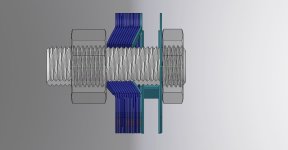
The ultimate torque arm (For <2kW and standard axles)?

fechter said:
Chalo said:
Buk___ said:

That's not a torque, son.

My thought also. In the diagram, it is not evident to me where this 200N is applied, so you need to help us out.

I am interested in what the amount of torque would be at that stress for comparison reasons. I know how much torque my hub motor can make. I want to know if the design will withstand that much.

You mean you engineering wizards can't work that out from the information given. Come on Chalo, now's the time to step up and show everyone your prowess. It's a simple calculation; just get the units right.
 
Translation: "Technical generalist" -- Jack-the-lad-of-all-trades; master of none.
 
My kind of engineering makes a flatted stud out of 4340 CrNiMo and then attaches it to a flex beam torque wrench to measure the arm's failure torque.

And then it makes a simple closed eye torque arm out of mild steel and performs the same test as a comparison.
 
Buk___ said:
Translation: "Technical generalist" -- Jack-the-lad-of-all-trades; master of none.

It's my favorite title I've ever held. Neal Stephenson came up with it.

My next card said "machinist", but that was an incomplete description.
 
Buk___ said:
You mean you engineering wizards can't work that out from the information given. Come on Chalo, now's the time to step up and show everyone your prowess. It's a simple calculation; just get the units right.

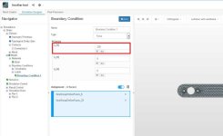
Clipboard03.jpg


Nowhere in this screen shot does it show where the 200N is applied nor does the picture of the part resemble the one being discussed.

All it shows is 200N. There is not enough information to answer my question. Since you seem to be dodging the question, I can only assume you don't know the answer either.
 
fechter said:
Nowhere in this screen shot does it show where the 200N is applied nor does the picture of the part resemble the one being discussed.

It does! Both faces to which the load boundary condition are being applied are clearly named. And that it what I'm up against.

When you have loud-mouthed senior members claiming rocket science engineering skills, but who do not know how a nut and bolt works, what chance is there is my being able to successfully explain that you do not specify "the motor torque" in a component simulation, but rather the forces that act on the component as a result of that torque.

fechter said:
All it shows is 200N. There is not enough information to answer my question.

Could it be that your question makes no sense in the context of the simulation?

The purpose of the simulation is to test whether the selected material and profile provide sufficient material to withstand the forces applied. (They do!)

What forces will be applied to the contacting faces of the TA by a given motor, depend entirely upon the torque that motor generates; the radius at which that torque acts upon the component; the arc (due to tolerances) through which that torque can accelerate before contact is made; the elapsed time (thus the rate) of acceleration; and a bunch of other factors which cannot be easily modeled, and which would vary from installation to installation.

The purpose of the simulation is to determine where, and at what levels the stresses and strains act within the material of the TA; to ensure that they are distributed in a way that keeps them within the materials physical characteristics; and allow the profile to be adjusted to ensure they do.

For now, I'm sick to the back teeth of the bait&switch tag-team put downs I've encountered here. I've never experienced a site quite like this for its claims of superior knowledge and skills, that are so absent from evidence, if you look at anything more than a cursory level; nor the levels of self-serving: let's-gang-up-on-the-newbie mentality.

And the following taunt is exactly what I've come to expect here:
fechter said:
Since you seem to be dodging the question, I can only assume you don't know the answer either.

I'm not dodging the question, just choosing (belatedly) to require some effort on the behalf of those choosing to question the design, in the hope to ensure that they have the requisite knowledge to understand the answer; before I expend time & effort to construct an answer.

Chalo is right in as much as it is possible that I adjusted the range of the graphical representation to disguise the levels of stress and strain being experienced under load. It is possible, but I did not. They are as the software defaults them.

He may be so used to having to tell lies to sustain his facade of technical know-how, but I am not; and it did not cross my mind to even consider such deception.

In any case, it is a precondition of the free account at the site (simscale.com) that all models are publicly available, and anyone here could go there, and run the model for themselves. But I am not encouraging that, because I do not want to have to expend my time spoon-feeding wanna-bes on the technicalities of how to use simulation software. If you have the skills, have at it.
 
amberwolf said:
It looks simpler, Im still imagining how it might be manufactured in a way I could do here, but I think I *might* be able to by hand, though ti would require fitting and filing till they matched each other. Not a mass production method, but something I could at least test on one wheel, and see if it does whats intended. If so, others could use them too.

Id like to see what the spring arm would do, myself. Its not a design anyone has tried yet, so its certainly worth exploring.

What diameter are your motor axles and how much axle protrudes beyond the dropouts?
 
fechter said:
Nowhere in this screen shot does it show where the 200N is applied nor does the picture of the part resemble the one being discussed.

(The screen grab was truncate on the right; it's the same part.)

Here for your delectation is an animation showing how a single layer distorts (exaggerated x20) as the axle rotates against it:

Single layer displacement(x20-unconstrained in Z) .gif

The colors on the surface show the exaggerated displacements.

Once the 12 layers are clamped together, with the frame on one side and the nut on the other, the apparent twisting in the Z-axis will be constrained and axle won't be able to rotate as far, restrained by the TA, but that takes a lot of resources (cpu/hours) to model and this single layer has already identified two areas where minor redesign will be beneficial.

(And no; its not getting rid of the slots!)

Care to suggest where you guys think the redesign should be?
 
Buk___ said:
What diameter are your motor axles and how much axle protrudes beyond the dropouts?

Theyre the MXUS 3K (45H / 4503 and 4504), with 14mm diameter IIRC (still 10mm flats).

IIRC the axle length is 30mm? 40? then about 5mm for the outboard dropout thickness, and I think its 8mm for the inboard dropout. So 25-35mm axle length outside the dropouts. But the dropouts can be rebuilt to move them farther apart, so that these spring arms can go inside them instead of outside, if its helpful.

(it would actually be necessary to put the inboard ones inside the dropouts, because the design of the clamp is a kind of T so theres no flat face on the inboard (outer) side of the inboard dropouts.)

I think the axle length is uncut on the rightside motor, and on the outboard side of the leftside motor, but its at least several mm shorter on the inboard side where I cut it down where the axle broke so I could weld it back on. (that was this past weekend)

https://endless-sphere.com/forums/viewtopic.php?f=2&t=67833&start=725#p1375149https://endless-sphere.com/forums/viewtopic.php?f=2&t=67833&start=725#p1374643
 
amberwolf said:
Buk___ said:
What diameter are your motor axles and how much axle protrudes beyond the dropouts?

Theyre the MXUS 3K (45H / 4503 and 4504), with 14mm diameter IIRC (still 10mm flats).

IIRC the axle length is 30mm? 40? then about 5mm for the outboard dropout thickness, and I think its 8mm for the inboard dropout. So 25-35mm axle length outside the dropouts. But the dropouts can be rebuilt to move them farther apart, so that these spring arms can go inside them instead of outside, if its helpful.

(it would actually be necessary to put the inboard ones inside the dropouts, because the design of the clamp is a kind of T so theres no flat face on the inboard (outer) side of the inboard dropouts.)

I think the axle length is uncut on the rightside motor, and on the outboard side of the leftside motor, but its at least several mm shorter on the inboard side where I cut it down where the axle broke so I could weld it back on. (that was this past weekend)

https://endless-sphere.com/forums/viewtopic.php?f=2&t=67833&start=725#p1375149https://endless-sphere.com/forums/viewtopic.php?f=2&t=67833&start=725#p1374643

Having looked at the close-up pics of your axle mounts, I honestly don't think there would be any benefit to using the spring TA on your setup.

With the axle being held by a very meaty steel pinch-clamp arrangement on the inboard end, there should be no axle acceleration -- nor even movement beyond the elastic yield of the pinch-clamp faces and axle flats -- for the spring to absorb.

Basically, unless something breaks again, they would be doing nothing.

If you still want to pursue it, then tell me what you need from me?
 
Buk___ said:
Care to suggest where you guys think the redesign should be?

Above my capability.

On a tangent, but still a redesign idea, can this approach be made to work for front motors in a fork? Lots of lower powered conversions use front motors and the consequences of a dropout failing are more severe for a fork than for a rear dropout.

I've followed you over here from the main torque arms testing thread as I think your designs are intriguing. The common sort of available torque arms seem sort of janky, especially for lower powered applications so I'm happy to see someone thinking seriously about this.

If you get to the point of having some made and they are not wildly expensive I'd be interested in in chipping in for a few sets.
 
-dg said:
Buk___ said:
Care to suggest where you guys think the redesign should be?

Above my capability.

On a tangent, but still a redesign idea, can this approach be made to work for front motors in a fork? Lots of lower powered conversions use front motors and the consequences of a dropout failing are more severe for a fork than for a rear dropout.

I've followed you over here from the main torque arms testing thread as I think your designs are intriguing. The common sort of available torque arms seem sort of janky, especially for lower powered applications so I'm happy to see someone thinking seriously about this.

If you get to the point of having some made and they are not wildly expensive I'd be interested in in chipping in for a few sets.

I briefly looked at the idea of trying to make a design (front or rear) that is universal enough to make it worth while having a batch made -- which significantly reduces the cost of having the parts laser or water cut -- and then heat treating and assembling and putting them up for sale.

I almost got arrested because I was noticed walking around a bike park taking photos of peoples dropouts :)

I reached the conclusion that there is so much variation in the shape and size of both front and rear dropouts that coming up with a single pattern that would fit a reasonable number of them would only be possible by recreating the existing, clunky, two-part designs that requires jubilee clip or some other kind of pipe clamp to attach the arm; and a nut and bolt to attach the clamp part to that arm.

That throws away most of the design goals I set myself: No extra tools or screws required to remove the wheel; small and neat; one-piece to make it easy to manage when re-installing the rear wheel with the deraileur -- which always seems to need 3 hands, even without the extra complication of getting a TA lined up and connected.

The principles of the design are simple enough that it should be easy for anyone to adapt it to the size and shape that fits their bike; but coming up with a single pattern that fits a range of bikes would be hard I think.

As for front dropout. There are so many variations -- underneath, in front of, or behind the stanchion; centrally mounted or inset; etc. etc. -- along with lawyer lips and not; disk brake mounts to clear or not; skinny fixed, through wide suspension, stanchions; I cannot see an even vaguely universal pattern.
 
Buk___ said:
I reached the conclusion that there is so much variation in the shape and size of both front and rear dropouts that coming up with a single pattern that would fit a reasonable number of them would only be possible by recreating the existing, clunky, two-part designs that requires jubilee clip or some other kind of pipe clamp to attach the arm; and a nut and bolt to attach the clamp part to that arm.

As for front dropout. There are so many variations -- underneath, in front of, or behind the stanchion; centrally mounted or inset; etc. etc. -- along with lawyer lips and not; disk brake mounts to clear or not; skinny fixed, through wide suspension, stanchions; I cannot see an even vaguely universal pattern.

And this is a common problem in the design of many "universal adapters" for conversion,... not truly universal or safely adequate for most needs. As I noted previously, this is great for "MY" particular needs. Although my heavy plate aluminum dropouts seem sturdy enough for my current 1500w-2000w use, if I were to "adapt" a motor GREATER than 2000W, I would CERTAINLY apply such a design or a similar modification of this that utilized the simple "leafed layers" given my particular needs and limitations. And for me,... I'd likely lose the "mount arm" in favor of simpler "plate" with 2-hole mounting.

I had found it necessary to replace my entire front fork assembly after a few attempts of using "disk brake adapters". And a particular brake adapter found for rear use, still required some modification for suitability.
 
$15 for a set of two when you buy a pair of training wheels with these brackets included at Walmart or any other store these are way stronger than any other torque arms you'll find on the market secured with a u bolt that goes around the fork. No need to wait for shipping. And only about fifteen thousandths of an inch clearance for axle no slop at all
 
JamieWlcox said:
$15 for a set of two when you buy a pair of training wheels with these brackets included at Walmart or any other store these are way stronger than any other torque arms you'll find on the market secured with a u bolt that goes around the fork. No need to wait for shipping. And only about fifteen thousandths of an inch clearance for axle no slop at all

A link would have been nice.

And do you realise that 0.015" is nearly 1/2 a millimeter?

If your "fifteen thousandths of an inch clearance" means all around, then on a 12mm axle, that represents 3.45° of rotation in either direction. Or 2.2715° each way for a 14mm axle.

Given a (relatively modest) motor that can accelerate 120kg from standstill to 30kph in say 3 seconds, do you have any concept of the force created when it snaps from drive to regen and is essentially unconstrained for 6.9° (4.6436°) of rotation before impacting 4 or 5 point contacts into the faces of your training wheel brackets?

Given your description of their original purpose, they are probably only designed to withstand bending forces from toddlers weights; not the point impact and sheer forces of an electric motor.

Best I can say -- good luck with that!
 
DRMousseau said:
Buk___ said:
I reached the conclusion that there is so much variation in the shape and size of both front and rear dropouts that coming up with a single pattern that would fit a reasonable number of them would only be possible by recreating the existing, clunky, two-part designs that requires jubilee clip or some other kind of pipe clamp to attach the arm; and a nut and bolt to attach the clamp part to that arm.

As for front dropout. There are so many variations -- underneath, in front of, or behind the stanchion; centrally mounted or inset; etc. etc. -- along with lawyer lips and not; disk brake mounts to clear or not; skinny fixed, through wide suspension, stanchions; I cannot see an even vaguely universal pattern.

And this is a common problem in the design of many "universal adapters" for conversion,... not truly universal or safely adequate for most needs. As I noted previously, this is great for "MY" particular needs. Although my heavy plate aluminum dropouts seem sturdy enough for my current 1500w-2000w use, if I were to "adapt" a motor GREATER than 2000W, I would CERTAINLY apply such a design or a similar modification of this that utilized the simple "leafed layers" given my particular needs and limitations. And for me,... I'd likely lose the "mount arm" in favor of simpler "plate" with 2-hole mounting.

I had found it necessary to replace my entire front fork assembly after a few attempts of using "disk brake adapters". And a particular brake adapter found for rear use, still required some modification for suitability.

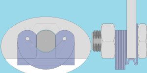
I did com up with a variation that might actually work for a fairly wide set of dropouts.
WrapUnderTA.jpg (Sorry, couldn't be bothered to resize it for display here.)

The layered spring is essentially the same, although I've adjusted the angle of the slot to allow the faces to better conform to small changes in the angle of the axle flats under load, and the diameter of the hole at the end, to reduce the effective spring rate as a result of simulation testing.

The sizes in the diagram (20px per millimetre), should be good for torques ranging from <20N.m to about 250N.m on a 12mm axle and somewhat more on 14mm. I haven't yet got the simulation to run to completion, but the clamping wings part is similar enough to the previous design to be okay.

The complication -- from the simulation point of view and the manufacturing at home, is the shape of the inner most layer, which wraps under the dropout.

The idea here is that as the nut is done up, the kinks in the bit that passes under the dropout, squeeze together, pushing the flat section in the middle up and into contact with the underside of the dropout. That clamping action provides the anti-turning mechanism precluding the need for an arm and drilling holes.

That kinky U shape would be awkward, but not impossible to form at home with simple tools, but would need to be sized to fit the frame it is going to be attached to. It might be possible possible to make a single sized component and attach different size 'packing pieces' that would be attached to the flat bit using (pop) rivets or screws. The packing pieces could be made from pretty much any old piece of metal that could be drilled and tapped.

Anyway, that's as far as the idea has gone for now.

I'm hoping to acquire some annealed spring steel plate (for postage costs only) suitable for making the OP design (top of this thread) for my machine sometime soon. It'll mean cutting the plates out by hand and fettling them to size; but I think I've worked out a way of doing that on-mass rather than individually.

Basically, clamping the rectangular pieces together and drilling the 4mm clearance hole through them all first, and then using a bolt to hold the pieces together whilst I drill, hacksaw and file their shape. I can't rivet them together a this early stage because I need to apply the set to the jaws individually; and the heat treatment will be easier done individually, with less mass to get to an even temperature.

I've even come up with a design or a simple jig to hold the parts whilst they are clamped into a vice to set the bends on the wings. Whether that is worth the cost and time to make for a single set for me I have my doubts.
 
Interesting concept, but the most basic simplicity is often the key to the best designs of durable dependability. And my specific needs are not the same as many others.
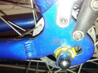
This photo best illustrates my dropouts identically. My axle is seated deeply as possible and I have no slippage at all. While the plate IS quite heavy, it also provides a large surface that CAN be drilled and tapped where needed (as I did to secure a caliper mount adapter).

As you can see, I have plenty to work with,.... jus no room for much of thickness beyond a few thin plates that would replace existing washers, as my axle is much shorter than what appears here.
 

Attachments

  • 11t1xft.jpg
    11t1xft.jpg
    148.1 KB · Views: 2,508
DRMousseau said:
As you can see, I have plenty to work with,.... jus no room for much of thickness beyond a few thin plates that would replace existing washers, as my axle is much shorter than what appears here.

Is that a motor behind there? It looks like an ordinary wheel.
 
DRMousseau said:
Buk___ said:
Is that a motor behind there? It looks like an ordinary wheel.

No motor in this pic,... jus a good closeup that depicts my exact dropout plate.

Ah. Okay. I would have dismissed the thought except that for all the world, that looks like a tabbed torque washer under your domed nut.

Three thoughts:

  1. The wrap-under layer is only 0.5mm thick and would fit around your dropout fine.
  2. It would replace 1 or two (or more) layers of the screw-plate/torque arm designs. One of the benefits of the layered design is the ability to vary the thickness to your requirements.
  3. A motor axle is likely to be longer.
 
DRMousseau said:
Interesting concept, but the most basic simplicity is often the key to the best designs of durable dependability.

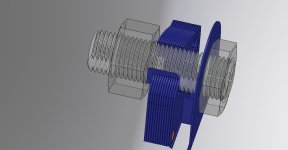
Latest iteration:
SpringPlateTAAssemblyView1.jpg
SpringPlateTAAssemblyView2.jpg

No drilling, screws or jubilee clips or extra tools required.

One wrap-under plate (lighter blue lower image) and as many or few of the identical darker blues as your axle accommodates.

Laser cut parts, bent with a couple of bits of scrap wood and a strong vice, heat treat with a blow torch and some dry course sand, and assembled with two brass rivets.

Should be good for ~10N.m per layer (with a minimum of 4 (3+1) required) on a 12mm axle and perhaps 15N.m for 14mm.
 
You say heat treat w a blow torch and coarse sand. For any steel? Why the coarse sand? I've been "bluing" big stainless steel nuts on my gas burner at home and produces some great colors instead of the silver. what you recommend to make the threads stronger?


I really like this design but limited in what will go in. Good for single speed with horizontal dropouts
https://imgur.com/a/CmnZUNx

Nice to see others obsessed with making torque arms. How much it cost to get a set made? These were 21$ with shipping for 4.
 
Back
Top