2018 Torque Arm Tests, Splined Interface Design and Tabbed Washers

e-beach said:
I am looking forward to tests with a Grin torques arms myself. Maybe using the type of fork that failed earliest.

I was hoping that by modelling Justin's failed attempt, and showing that the results of the simulation produced similar results, I might demonstrate the efficacy of simulation testing. To be convincing, I need more accurate data than I can extract from pictures. (Due to the loss-y nature of the jpg format, the best I can achieve is about ±0.5mm/20thou of accuracy on the dimensions, which isn't good enough to be convincing.)

If I could make the case for simulation testing, then I could offer to put some of his design variations through that testing and perhaps contribute by saving him some time/cost producing prototypes for destruction.

Real life is always the real test, but if you can narrow down the possibilities, and guide the design process by seeing where the failures are likely to occur, in software; it can save a lot of time and money in the real world.
 
I agree that simulation can be very beneficial to a design concept. However, Grin already has the testing equipment and the torque arms. Acquiring a few used forks for the propose of testing the standard torque arm in comparison to the un-torqued-arm forks would be very easy. No need for computer input this time. Get comparable forks and slap on the Grin torque arms. Torque the nuts tight and torque away!

:D
 
e-beach said:
I agree that simulation can be very beneficial to a design concept. However, Grin already has the testing equipment and the torque arms. Acquiring a few used forks for the propose of testing the standard torque arm in comparison to the un-torqued-arm forks would be very easy. No need for computer input this time. Get comparable forks and slap on the Grin torque arms. Torque the nuts tight and torque away!

:D

You miss my point. But what's new.
 
Buk___ said:
......You miss my point. But what's new.

Oh, you made a point? Well, that was smart of you.

And here all I was calling for was an apples-to-apples comparison. I guess it was pretty stupid of me to call for an apples-to-apples comparison. :lol:

:D
 
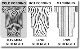
In forged dropouts it's difficult to model the real grain structure related strength, but you're right that simulation rocks for this sort of application, and optimizing with FEA is a huge time saver for getting things ballparked to begin tests.


Buk___ said:
e-beach said:
I am looking forward to tests with a Grin torques arms myself. Maybe using the type of fork that failed earliest.

I was hoping that by modelling Justin's failed attempt, and showing that the results of the simulation produced similar results, I might demonstrate the efficacy of simulation testing. To be convincing, I need more accurate data than I can extract from pictures. (Due to the loss-y nature of the jpg format, the best I can achieve is about ±0.5mm/20thou of accuracy on the dimensions, which isn't good enough to be convincing.)

If I could make the case for simulation testing, then I could offer to put some of his design variations through that testing and perhaps contribute by saving him some time/cost producing prototypes for destruction.

Real life is always the real test, but if you can narrow down the possibilities, and guide the design process by seeing where the failures are likely to occur, in software; it can save a lot of time and money in the real world.
 
liveforphysics said:
In forged dropouts it's difficult to model the real grain structure related strength...

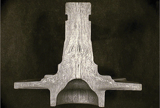
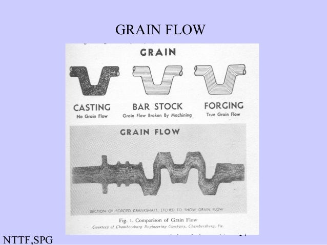
Closed die forging -- hot or cold -- produces very desirable and repeatable grain structure:
GrainFlowSketch.jpg
f1-1037.png


Which is why it is used for the manufacture of the highest stressed component in ICE engines, the gudgeon pins; and even 1-piece performance crankshafts:
06forging-17-638.jpg


But die costs are huge and only make sense if you are manufacturing 10s of thousands.
 
Buk___ said:
justin_le said:

Justin, Any chance you could post a dimensioned version of this design?

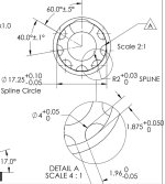
Yes, for sure. Here is the dimensioned drawing of the axle itself showing the actual spline definition:
Axle Spline Drawing.jpg

I don't have a drawing handy of the torque arm itself since we just went straight from the 3D CAD to CAM on the CNC mill, but I can go ahead and have that made too. I'm quite interested as well in seeing what a detailed FEA shows in comparison to the actual real world testing.

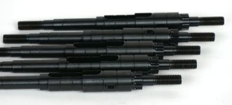
Also, we received the first mini pilot batch of splined axles from MAC motors last week and they look good! (except for the thread pitch obviously being coarser than our specified 1.0mm)
5 pcs Splined Axles.jpg

The additional bench testing will resume soon and we'll have more results data to share. Robbie will likely take over the posting on this thread as I've got a few other things to tend to this month!
 
justin_le said:
I'm quite interested as well in seeing what a detailed FEA shows in comparison to the actual real world testing.

I've had to shrink this using lossy compression in order to get it down to a size that will upload here (the original 15MB), which has made it rather small and fuzzy, but you can still see:

  • The way the upper arm moves left relative to the lower.
  • The ring being forced open as the load increases.
  • Finally, the strain on the spline at 5 O'clock climbing rapidly, and finally shearing through.

I rate that a pretty darn close match.

The maximum torque that design can handle seem to be about 31-32N.m; but that's before any consideration is given to cyclic fatigue and strain hardening.

splinedTA[200N.m][opt].gif
Bigger, clearer version.

More to come, but its a nice validation of the methodology.
 
Ok, nice work, and correct me if I am wrong,....Are we viewing your gif as from the inside of the torque arm that is next to the motor?

Also, where is the rest of the torque arm setup. You seem to be missing a plate.

:D
 
e-beach said:
Ok, nice work, and correct me if I am wrong,....Are we viewing your gif as from the inside of the torque arm that is next to the motor?

No. If you follow the link to the bigger version, it also includes a ghost of the axle that shows the view is from the outside.

If you're worried about the direction of rotation, imagine you are leaning over the bike from t'other side and looking at it upside down :)

e-beach said:
Also, where is the rest of the torque arm setup. You seem to be missing a plate.

You'll have to imagine it :)

In this simulation, the arm is fixed by the inner face of the hole in the lower arm (as viewed in the gif) and the inner face of the hole in the upper arm, which is allowed to flex (a small amount) relative to the lower arm. This allows the twist, due to the clearance around the pinch bolt and the deformation that occurs there in real-life, without making the model so complex that it requires hours to run.

In anycase, as Jason's tests show, that extra plate made little or no difference.
 
So what was the final outcome of this tread?

:D
 
e-beach said:
So what was the final outcome of this tread?

The outcome is awesomeness about to hit the market! :D

In the end we revised the design substantially based on the nature of how the earlier tests has failed. Instead of having something of a 'U" shaped arm we now have a circular piece with a wire slot that is a snug press fit over the axle and has a series of holes around the perimeter, and then a second arm with a circular cutout fits over top of this and confines the 'C' shaped plate so that it can't spread out or deform.

Easier perhaps in pictures. Here is how the completed motor itself looks like with the splined axle and cable ext:

View attachment 4

This is using the same 17mm standard axle diameter shared by a large number of geared and DD hub motors so it's a torque interface and cable exit that should be possible for other manufacturers to get behind.

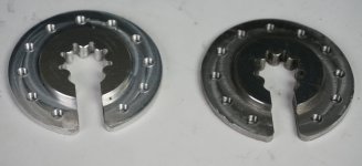
Here is the matching circular plate that mates with this splined interface. On the right is a version machined from steel, and on the left is one milled from 7075 aluminum.
GMAC Torque Arm Plate.jpg

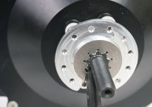
We dialed in the machining of this to be basically an interference fit over the axle. You can pry it off with a screwdriver or gear puller and get it on by tapping it with a tube, but once it's on there it's as snug as possible with no play at all:

GMAC Plate on Axle.jpg

The arm that links this to the frame completely encloses the plate in a full circle, and that basically confines this splined plate against the kind of deformation that could cause a disproportionate stress on just a few of the teeth.

View attachment 1

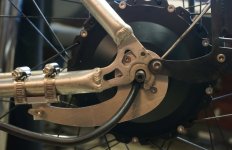
The end result is a design that hits all of our initial objectives set out in this thread.

GMAC on Bike.jpg

We had 6 of these motors produced to this spec late last year and have them running both on test bikes and also on an automated test bench which I'll talk about next. Although these are geared MAC motors with high torque, we had them produced with no clutch so that they are also capable of regenerative braking. The torque arm design needs to cope not just with single direction torques of 100Nm but back and forth torques of this magnitude too.
 
One of the things we posted up on instragram last month was a video showing the testing station that we built for cycle testing the torque arm design.
https://www.instagram.com/p/Bsg92CNHCCZ/

Last year on this thread we were doing failure testing where we kept increasing the torque on the axle until something broke, but in practice most items fail from fatigue after many cycles rather than being pushed in one go beyond the breaking point. This is especially true of aluminum, and for a number of reasons it's still our preferred material for making the torque arms. So here is the contraption that we made up over the holidays. (For video click link above)


The system basically lets us run a 10T locked clutch GMAC motor forwards and backwards at max current of the Phaserunner (96A), giving an accelerated cycle testing of all the hardware associated with this torque arm and kit design, with the worse case torque levels that it could see in practice.

If we run it back and forth too intensely then the MAC motor overheats, so in the end we power it forwards for 1 second, then pause for 8 seconds to let the motor cool, the run it in reverse for 1 second, pause etc. It let's us do about 10,000 cycles a day. The motor ends up getting to about 120 oC steady state at this duty ratio, while the Phaserunner sits much cooler at about 45 degrees.

Anyways, after the first 10,000 cycles like this something failed mechanically in the torque arm assembly and the safety limit switches kicked in and stopped the motor from destroying itself. We replaced this failed item and resumed the experiment, and once again one day later it failed again!

Anyone want to take guesses at which part was the weak link in the setup pictured above?
 
justin_le said:
Anyone want to take guesses at which part was the weak link in the setup pictured above?

I'll guess it was the P-clamp on the chainstay. Any part that can deflect will be subject to fatigue failure.
 
fechter said:
justin_le said:
Anyone want to take guesses at which part was the weak link in the setup pictured above?

I'll guess it was the P-clamp on the chainstay. Any part that can deflect will be subject to fatigue failure.

I agree, it's a lever so the max torque will be at its end where the poor clamp is situated it with the power levels it's being tested at there will be 100's of NM applied 100's of times an hour.

Top work on this by the way, I think a clamped spline interface is the best of all but complex and no hub carrys it as standard, so its the oval open clamped drop out thats the simplest way to go for high power or a slow high torque ride.

I've got a dual 4mm high carbon stainless closed oval torque arms, and after 500miles at 2kw at 36v so plenty of grunt there's no visable wear lots more life left, but they were laser cut and self designed so can't be used to compare really.
 
A splay stopping system.... Nicely done! Very nicely done indeed!

justin_le said:
Anyone want to take guesses at which part was the weak link in the setup pictured above?

+1 on the P-clamp. I am guessing the bolt hole stretched and then broke.

:D :bolt:
 
fechter said:
I'll guess it was the P-clamp on the chainstay. Any part that can deflect will be subject to fatigue failure.

Yup you guys are pretty spot on there, who needs physical testing when we have the collective wisdom of ES gurus to predict what will happen!

We tried two different models of 'P' clamp since this is the most obvious, common and established method of attaching torque arms on bicycles (coaster brakes, certain internal gear hubs etc). The first one was stainless steel and the 2nd was a thicker gauge galvanized steel model. Neither was at all up to the task. They didn't fail at the bolt hole but at the bend where most of the back and forth flex was taking place.

View attachment 1


This wasn't a complete surprise since we've seen 'P' clamps fail in a similar manner when used to secure our Grin All Axle hub motor torque arms too. Usually (with a sample instance of 3 field failures) that's after about 6 months of regular commuting with regen, so to first order it seems 1 day on this test jig is equivalent to 6 months of road usage.

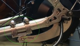
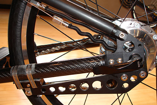
In the current iteration we've now got a machined aluminum block held on rigidly to the chainstays with a pair of hose clamps as you see on the unit installed on the bike.

CNC Torque Arm Mount.jpg
This doesn't looks as neat as a P clamp but it is quite rigid and shows no signs at all of failing. The attachment point is 12.5cm from the axle, so 100Nm of motor torque is 800N or 175 pounds. It's pretty impressive watching just how much the entire frame triangle stretches and deforms from this during each torque cycle.

The block is slotted rather than having just a hole for the torque arm bolt, and that way it's possible to replace the M5 bolt with a quick release and allow the arm to slide out easily for wheel removal instead of having to fully remove the fasteners.

Anyways, so after solving the 'P' clamp weakness with the above solution, things were ticking along for many more 10's of thousands of cycles. But then we started seeing another problem surface which was causing the fail safe limit switch to trigger and shut down the experiment. At first it was happening every few thousand cycles, everything looked fine so we'd just resume and it would keep running again. Then it became more frequent like every few hundred cycles, and then we had to stop to see what the heck was going on.

Any guesses on what was next inline to come apart?
 
I'm going to guess the aluminum rear triangle fatigues at the HAZ next to a weld and grows a crack until it can deform enough to trip the limit switches.

Looks like a huge improvement in torque arms!
 
I would say, the teeth on the aluminum circular plate started to deform.

:D :bolt:
 
liveforphysics said:
I'm going to guess the aluminum rear triangle fatigues at the HAZ next to a weld and grows a crack until it can deform enough to trip the limit switches.

Ha, not a bad theory but so far the aluminum frame appears to be holding fine. I will say that if the FRAME fails structurally before the torque arm does, then we'll be able to call the torque arm design something of a success :)

e-beach said:
I would say, the teeth on the aluminum circular plate started to deform.

Luckily no, at least so far the teeth so far are looking rock solid. That's not to say that there might night be microscopic cracks forming that aren't yet visible, but as far as there being any play or slop it's still perfectly tight on there.

....

In the end, it was the 6 screws that hold the arm piece to the circular plate which started to unscrew. These were put in with blue loctite but only snugged up hand tight, not using an impact driver or torque wrench:


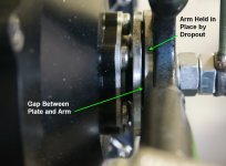
At first we could see there was a little bit of relative rotation between the circular plate and the arm on each cycle, like a fraction of a mm, and over the course of the test it increased to almost 2mm of travel. When you look at the side view you can see what happened. The screws loosened up completely but then bottomed out against the dropout face, allowing the arm and circulate plate to separate with a gap between each other, while the dropout face effectively retained the assembly in place.

Gap Side View.jpg


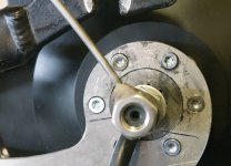
And this is what it looked like with the motor removed from the jig. You can see how the backed off screw heads were rubbing the paint off the bike frame with each cycle.


All Loose Screws.jpg

Luckily, this didn't seem to damage the the threads or anything so we removed the screws, put in a fresh dab of loctite, and this time screwed them back down with a small impact driver. It's now got another 30,000 cycles with no sign of the screws coming loose again. The lesson learned that we'll definitely need to include a proper torque spec for tightening these bolts.

Looks like a huge improvement in torque arms!

Thanks! Our ultimate goal is to make after-market torque arms a thing of the past, and just have all our motor include their own integrated arm design with zero slop or fitment issues. The plan is to keep this experiment running until we hit 1 million cycles. If it survives that I think we can have a lot of confidence that the design with 7075 aluminum is fully up for the job.
 
justin_le said:
[In the current iteration we've now got a machined aluminum block held on rigidly to the chainstays with a pair of hose clamps as you see on the unit installed on the bike.

CNC Torque Arm Mount.jpg

Just like the first iteration torque arm of the Rohloff hub!
rohloffspeedbone.jpg
 
justin_le said:
..........In the end, it was the 6 screws that hold the arm piece to the circular plate which started to unscrew.......
In the words of Maxwell Smart, "Missed it by that much."..... :lol:

Although it did seem to me that the failure would be between the motor and the anchor point of the torque arm. Torque specs and thread locker for sure, but what about left handed threads?

:D :bolt:
 
Chalo said:
Just like the first iteration torque arm of the Rohloff hub!
rohloffspeedbone.jpg

Ha awesome, thanks for sharing that. Nice design convergence and it looks like the Germans take no chances on their torque arms either!

I guess that a person standing and reefing on the cranks with the Rohloff IGH in the easiest gear produces a reaction torque from the internal reduction a similar magnitude to a powerful hub motor. And this torque direction would reverse when switching above and below the 1:1 transmission ratio, so requirements are not unlike our regen hub motor needs!
 
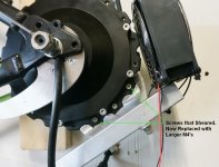
Damn this cycle testing is taking its toll on things. We started having hiccups on the station just a few days after re-tightening the arm/plate screws with loctite, and noticed that all but two of the M3 bolts holding the motor housing to the lever arm that goes to the damper had sheared off! We used M3's since we didn't want to enlarge the spoke holes and figured 7 of these at the flange radius would be enough, but back and forth cycling really does wonders at breaking stuff.

GMAC Sheared Flange Screws.jpg

Anyways, these were replaced with M4 screws as shown above, the experiment resumed, and a few days later we noticed that the torque arm screws were becoming loose on the torque plate again, only this time when we ended up stripping the threads on re-tightening, which had obviously been compromised from the screws being worked loose and then getting tugged back and forth.

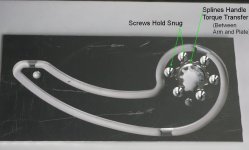
That seems like a design flaw so now what we've done is revisited the interface between the plate that slips over the axle and the arm that connects to the frame. Instead of a circular cutout that relies on the six M4 screws to transfer torque between them, we've included another wavy spline interface so that these two pieces are intrinsically locked for torque coupling.


Now the screws just need to hold the two pieces flat against each other, but they don't have to transfer the 100 Nm of torque. At the radius of the screw holes (22mm), that was almost 75 kg or 165lb of constant back and forth shear on each screw

GMAC Torque Arm Revised with Spline.jpg

It's been interesting to watch this all play out and I'd love to do the same at some point with more conventional torque arms. Unfortunately if we switch over to this wavy spline arm on our test station, it means we're starting the test on the inner axle splines from scratch again which was the original purpose of the whole rig. The 150,000 or so cycles accumulated so far get reset to zero which is a little unfortunate.
 
I wonder if the flat head taper causes the fastener to stretch and loosen given the back and forth torque creates a wedge lever. You might get away without the second spline with socket heads. Lug nuts on car wheels are tapered but they have much more meat than a flat head screw

Look at ur disc brake rotors on ur bike. No taper on the screws

Button or socket head
 
Back
Top