KT motor controllers -- Flexible OpenSource firmware for BMSBattery S/Kunteng KT motor controllers (0.25kW up to 5kW)

ok, I just dont see any possible reason to blame the dc dc regulator. That net is completely independent.
I am tempted to flash this, but I am waiting for a second controller to arrive from China in order to have a backup. I need this controller working.
 
lqbweb said:
ok, I just dont see any possible reason to blame the dc dc regulator. That net is completely independent.
I am tempted to flash this, but I am waiting for a second controller to arrive from China in order to have a backup. I need this controller working.

As a reason to blame it i see that, it was working before.

You can try to put the original back. Its quick switch
 
geofft said:
Hmmm, you don't need to worry about that. But it is binary coding of the signal, like 5 is 101, 3 is 010, etc. Where 1 is 5 volts and 0 0 volts.

Ah...ok, now I understand.
There may happen an issue: let's say the right sequence is ok and the motor runs ok, BUT on the backwards direction..... because to run on the contrary direction, that sequence will be the same but on the inverted direction. The thing is that seems that the angle that FOC should be "done" is different for each side.
Well, let's see what you get and then we can think. Please confirm later that you are using the same connections with original and our firmware.
 
honya96 said:
lqbweb said:
ok, I just dont see any possible reason to blame the dc dc regulator. That net is completely independent.
I am tempted to flash this, but I am waiting for a second controller to arrive from China in order to have a backup. I need this controller working.

As a reason to blame it i see that, it was working before.

You can try to put the original back. Its quick switch

ok, this morning I just received my backup controller. Now I can confirm that it is the frocking software, either from the LCD (LCD6) or the controller.

With a new controller, without any mod, it is happening the same. Somehow the battery indication has some sort of memory and autolearning I think. Not even resetting it fixes it.

I will finish up the bike during this week, and go for a full discharge cycle.
 
casainho said:
geofft said:
Just tried this, things don't seem quite right.
Please try the following process. I wrote it to install firmware instructions and if they are ok to you, I will put online:

Hall sensor connections

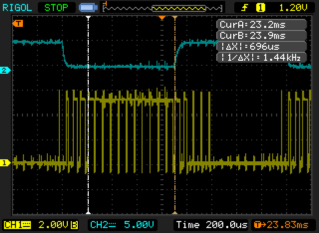
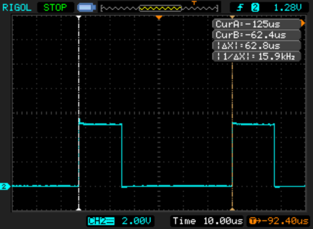
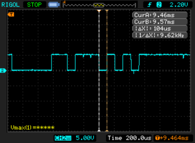
With the motor phase wires disconnected (it is recommended to insulate with tape the phase wires) and the hall sensor wires connected to the motor controller, use a multimeter to measure the voltage of each hall sensor wires.

Rotate the wheel slowly by hand in the backward direction and the motor will rotate (if you are using a geared motor, it is the only direction which the motor will rotate).

For the hall sensors to be correctly connected, you must make sure the voltages sequence is the following (and repeats over and over) - if not, you will need to exchange the wires up to get the right sequence:

Position | Blue wire: hall sensor C | Green wire: hall sensor B | Yellow wire: hall sensor A
2 | 0 volts | 5 volts | 0 volts
6 | 5 volts | 5 volts | 0 volts
4 | 5 volts | 0 volts | 0 volts
5 | 5 volts | 0 volts | 5 volts
1 | 0 volts | 0 volts | 5 volts
3 | 0 volts | 5 volts | 5 volts

Phase wires connections

Yellow wire: motor phase A
Green wire: motor phase B
Blue wire: motor phase C

After having hall sensors with the right sequence and with the motor controller turned off, connect the motor controller green wire phase B (middle wire on controller board, being the yellow and blue on the extreme to run the sides) to the motor green wire. Now connect the other wires with the same colors and finally try to run the motor starting with a low throttle value and with a protected lab power supply or battery pack with a BMS. If the motor don't work, makes noise, ask to much current, etc, exchange the yellow and blue wires between them, keeping the green wire - try again to run the motor.
If the previous ways was not ok for running the motor, you can try other motor phases combinations.


Just completed this:-

Hall seq test reduced.jpg

...it wasn't easy to do because with the 13.2:1 reduction on my gear motor the distance between individual steps at the wheel rim is just a few mm and often the residual flux in the motor coils would cause it to 'jump' forward past the required test position. Anyway, in the end I can confirm that my hall sensor sequence is exactly as shown in your list above.

Then played around with motor phase connections, tried all six possible combinations but the only sequence that would run was the 'straight' option (B-B, G-G, Y-Y), all other sequences gave major issues. These 'straight' connections (both hall and motor phase) are the same that I use for the stock controller.

Not sure if that is of any help to you. Although the latest fw (with the revised FOC) gave me the running issues we discussed before, the previous version runs extremely well, the only issue that bothered me was the high controller (not motor..) temperature compared to stock fw, so you are pretty close to getting things right.... :)
 
Thank you Geofft. Great that you tested all the combinations. Was there a combination that motor rotated backwards??

Good to know that the same colors on wires works and my motors also.

If the controller is getting hot, you are getting also lower range, right??
 
casainho said:
Thank you Geofft. Great that you tested all the combinations. Was there a combination that motor rotated backwards??

Good to know that the same colors on wires works and my motors also.

If the controller is getting hot, you are getting also lower range, right??

From my experience there is only one working phase wire combination for each hall combination so from all 36 there is 3 forward and 3 reverse.
I read somewhere that there should be 1 best forward and 1 reverse but for me they all seem to be running well.

Geofft tried only those six from which one is running forward.

I don't understand why are you even trying this now?
 
casainho said:
Thank you Geofft. Great that you tested all the combinations. Was there a combination that motor rotated backwards??

Good to know that the same colors on wires works and my motors also.

If the controller is getting hot, you are getting also lower range, right??

I think one setting after much juddering spun momentarily in reverse, but no setting gave anything like a 'true' reverse. TBH I find it hard to accept that my hall/phase connections are not correct, any changes in these would mean it would not run with the stock fw which surely can't be right?

I think the range is a little reduced compared to stock, but I haven't done a 'normal use' full range check for a while. If I was forced to guess I would say range has suffered maybe 5-10%.
 
geofft said:
TBH I find it hard to accept that my hall/phase connections are not correct, any changes in these would mean it would not run with the stock fw which surely can't be right?
Well, I develop with my motor and controller. You have a different motor and controller. With your tests I think we did learn more about this subject and I am more confident that this controllers and motors from China use the same wiring between them which is great.

Also I think that procedure to validate the hall sensor connections and phases is now validated.

So back to the issue, if your motor runs but the controller get's hot, maybe is just some small angle adjust... I didn't had chance to do deep testing. And I remember that angle FOC was at +30 degrees from what I was expecting... maybe it is wrong and I need to remove that 30. I am away from home up to the weekend, maybe I will try and ask to you to test, if you don't mind.
 
casainho said:
geofft said:
TBH I find it hard to accept that my hall/phase connections are not correct, any changes in these would mean it would not run with the stock fw which surely can't be right?
So back to the issue, if your motor runs but the controller get's hot, maybe is just some small angle adjust... I didn't had chance to do deep testing. And I remember that angle FOC was at +30 degrees from what I was expecting... maybe it is wrong and I need to remove that 30. I am away from home up to the weekend, maybe I will try and ask to you to test, if you don't mind.

No problem, happy to help where I can.. :)
Could MOTOR_ROTOR_OFFSET_ANGLE be relevant to controller temperature? I don't mind experimenting further with this if it may help.

BTW:- For me there is no rush to fix these things, the bike I'm using for this is just a test bike, I have other (BBS02 mid drive) bikes for riding if I need. So take your time... :wink:
 
Have you seen guys that for instance the phaserunner has a mode to autotune the motor? You are meant to spin the motor by hand i think while connected to the computer. Is this anything useful for you? You could figure out the sequence and angles maybe?
 
geofft said:
No problem, happy to help where I can.. :)
Could MOTOR_ROTOR_OFFSET_ANGLE be relevant to controller temperature? I don't mind experimenting further with this if it may help.

BTW:- For me there is no rush to fix these things, the bike I'm using for this is just a test bike, I have other (BBS02 mid drive) bikes for riding if I need. So take your time... :wink:
Code:
// this value of 174 (244 degrees; 170 would be 239 degrees) was found experimentaly
// seems to be about 180 + 60 degrees; were I expected to be 180 degrees
#define MOTOR_ROTOR_ANGLE_FOC 	(174 + MOTOR_ROTOR_OFFSET_ANGLE)
Please adjust the "174" value to something between 110 and max of 255 (including the sum of MOTOR_ROTOR_OFFSET_ANGLE).

Note that 20 equals to 30 degrees, 31 to 45 degrees, 42 to 60 degrees. I would say maybe the final value will be some of that round numbers (+ or -): 30, 45, 60 or 90 degrees.

I am away from home this week but I strangely feel well here :) -- a lot of people using also ebikes here in Tubingen:


Electric motors have horrible efficiencies at low RPM. This can be seen well on the ebikes.ca simulator. The rest is wasted as heat in the windings.

Do you think it would be a cool idea to optionally parametrically scale the phase current limit with motor rpm? e.g.

(rpm/A)^(1/3) where A=max rpm

Example: A=300rpm -> At very low speeds like 50rpm you only get 55% max phase current, which prevents overheating. At 300rpm you have nominal 100%. A different function might be better suited, this is just for illustration purposes.

One could also set A lower than max rpm to get an extra current boost above A rpm (where efficiency is good)
 
1N4001 said:
Electric motors have horrible efficiencies at low RPM. This can be seen well on the ebikes.ca simulator. The rest is wasted as heat in the windings.

This is not correct. If you use the simulator with the setting for a torque throttle you will find that the motors are very efficient across a wide band of rpm.

However, motors have higher losses with higher currents (I^2), which can for typical ebike motors and controllers only occur at low rpm. But as long as the phase current is limited to reasonable values efficiency remains good.
 
1N4001 said:
Electric motors have horrible efficiencies at low RPM. This can be seen well on the ebikes.ca simulator. The rest is wasted as heat in the windings.

Do you think it would be a cool idea to optionally parametrically scale the phase current limit with motor rpm? e.g.

(rpm/A)^(1/3) where A=max rpm

Example: A=300rpm -> At very low speeds like 50rpm you only get 55% max phase current, which prevents overheating. At 300rpm you have nominal 100%. A different function might be better suited, this is just for illustration purposes.

One could also set A lower than max rpm to get an extra current boost above A rpm (where efficiency is good)
That is not a priority for me. Also I don't feel the need for that so I am not motivated to do it.

My suggestion is for you to write o the issue tracker as a feature, you can put all the information there so will not be forget over the time and maybe in future it can be implemented.
 
1N4001 said:
Electric motors have horrible efficiencies at low RPM. This can be seen well on the ebikes.ca simulator. The rest is wasted as heat in the windings.

Do you think it would be a cool idea to optionally parametrically scale the phase current limit with motor rpm? e.g.

(rpm/A)^(1/3) where A=max rpm

Example: A=300rpm -> At very low speeds like 50rpm you only get 55% max phase current, which prevents overheating. At 300rpm you have nominal 100%. A different function might be better suited, this is just for illustration purposes.

One could also set A lower than max rpm to get an extra current boost above A rpm (where efficiency is good)

Your idea is not correct. It does not work like that.

You use high phase current only at startup, so if you limit it like that, you will have to push the bike to get it moving.
 
honya96 said:
You use high phase current only at startup
Not true, this only applies if you "run out of" battery voltage to keep the current flowing. In a system with sufficiently high battery voltage at full throttle, phase current stays constantly at the current limit. Just look at the motor simulator and compare "motor current" at different speeds.

so if you limit it like that, you will have to push the bike to get it moving.
No, it's a matter of how you set it up.

If before you had a phase current limit of 15A due to excessive heat at low speeds, you could now set it to 20 or 25A. Your low speed current/torque ideally remains unchanged, but your high speed current/torque would be significantly improved, possibly allowing you to reach higher speeds too.

casainho said:
That is not a priority for me. Also I don't feel the need for that so I am not motivated to do it.

My suggestion is for you to write o the issue tracker as a feature, you can put all the information there so will not be forget over the time and maybe in future it can be implemented.
Understandable. I'll do that.
 
1N4001 said:
honya96 said:
You use high phase current only at startup
Not true, this only applies if you "run out of" battery voltage to keep the current flowing. In a system with sufficiently high battery voltage at full throttle, phase current stays constantly at the current limit. Just look at the motor simulator and compare "motor current" at different speeds.

so if you limit it like that, you will have to push the bike to get it moving.
No, it's a matter of how you set it up.

If before you had a phase current limit of 15A due to excessive heat at low speeds, you could now set it to 20 or 25A. Your low speed current/torque ideally remains unchanged, but your high speed current/torque would be significantly improved, possibly allowing you to reach higher speeds too.

casainho said:
That is not a priority for me. Also I don't feel the need for that so I am not motivated to do it.

My suggestion is for you to write o the issue tracker as a feature, you can put all the information there so will not be forget over the time and maybe in future it can be implemented.
Understandable. I'll do that.

Try it on road, not simulator. You will find that it's non-sense.

We all want the oposite of what your idea will offer.
 
Try it on road, not simulator. You will find that it's non-sense.
Nope. The simulator is pretty good once you understand it. I'm fairly sure your "on the road" system is just limited by battery voltage, hence the confusion.

This is an example system whose max speed is limited by voltage. You see the obvious knee at 25kph, which is the point where the motor is generating so much voltage itself that phase/torque current cannot be kept up. Up until that point it remains pretty much constant (controller current-limiting). The resulting speed is the intersection of red motor power and black load.

Equip this system with a higher voltage battery and you'll get this. Now the max speed is limited by torque. You'll notice it intersects before the knee. The motor could still accelerate further, but the phase current/torque limit needs to be raised for this.


You state you want maximum torque from the start. Understandable.

But there are use cases for intentionally limiting torque at low speeds: Less battery usage, or climbing hills at slow speeds. BionX even offer a mountain mode which does just that, to reduce heat during long climbs.

Another use case would be for owners of torque-limited systems. Keep the start current/torque the same (which is entirely doable), but "boost" it at high RPM, to raise the top speed. The point is to squeeze more power out of the motor under conditions when there is still untapped potential.
 
Concerning regen:
Here is a good explanation how our PWM is working as step-down converter in motor mode and as step-up converter in regen mode.
Here also is described to use the BEMF that belongs to a certain rpm for controlling the regen, like I proposed some posts before :)....

https://www.roboteq.com/index.php/applications/100-how-to/156-controlled-regen-braking

regards
stancecoke
 
casainho said:
Snickers said:
So, do you think I can be face to magic smoke with my S06S boosted to (60V 55A) ~3KW* used with a direct drive motor?
Maybe you should try with a new one before testing with your custom version.
Ok, it’s safer. I order some new S06S and LCD3. It will just take some time to receive them.


Do you make some release in order to identify firmware version afterward?
Do you plan to use the LCD3 as a piloting S06S for the FOC motor parameter in real time?
 
1N4001 said:
Another use case would be for owners of torque-limited systems. Keep the start current/torque the same (which is entirely doable), but "boost" it at high RPM, to raise the top speed. The point is to squeeze more power out of the motor under conditions when there is still untapped potential.

I said allready that youre wrong, maybe someone will come up to teach you how it works but its a waste of time for me.
 
casainho said:
this value of 174 (244 degrees; 170 would be 239 degrees) was found experimentaly
// seems to be about 180 + 60 degrees; were I expected to be 180 degrees
#define MOTOR_ROTOR_ANGLE_FOC (174 + MOTOR_ROTOR_OFFSET_ANGLE)[/code]
Please adjust the "174" value to something between 110 and max of 255 (including the sum of MOTOR_ROTOR_OFFSET_ANGLE).

Note that 20 equals to 30 degrees, 31 to 45 degrees, 42 to 60 degrees. I would say maybe the final value will be some of that round numbers (+ or -): 30, 45, 60 or 90 degrees.
I've been having a play with the FOC angle as you suggested here, used the training stand with a fixed load/speed and measured battery current, also assessed motor running. The user adjustment for this in config.h (MOTOR_ROTOR_OFFSET_ANGLE) was left at '0'.

I have found the '174' setting is, for me , at the extreme upper end of the working range, in fact when set to 180 the motor malfunctions and will not run. For me the 'sweet spot' seems to be around 120-140, at this setting the motor operates really smoothly with good torque. I think 130 actually equates to 180deg, your 'expected' figure?

It seems odd that our two motors (Q85 vs Q128H) have such different requirements for the FOC angle, differences outside the normal range of any manufacturing tolerances you would think. It would be interesting to get some input from other testers, has anybody else experimented with this?

After a 4-5km test ride the motor was virtually cold but I still had a pretty hot controller (around 72C at the mosfets), so it looks like some improvements still need to be made here. I'll fiddle further with the FOC setting during the week but I have a feeling the cause of this excessive (compared with stock) controller temperature won't be found here.

I'm not sure how good my logic is here, but with a good working FOC I'm thinking that the angle that gives best efficiency should be quite clearly defined, but that seems not to be the case. In fact settings for the angular adjustment of 100-160 (140-225deg?) all seemed to give similar results on the test stand. (I have only as yet tried '130' (180deg) on the road). This makes me wonder if the FOC is really operating as you guys intended, maybe we need to do some more tests here. Anyway, I will test more when I can find time during the week, let me know if you want anything else tried.
 
I just modifed a BionX igh3 Motor for use with our firmware (my fork at the moment). I use it in the testbench for regen trials, after I ruined the gearwheels of my Sanyo Dynamotor.
FOC works fine with the Bionx. Even at regen with the algorithm I descibed before.

regards
stancecoke

s-l1600.jpg
 
geofft said:
casainho said:
this value of 174 (244 degrees; 170 would be 239 degrees) was found experimentaly
// seems to be about 180 + 60 degrees; were I expected to be 180 degrees
#define MOTOR_ROTOR_ANGLE_FOC (174 + MOTOR_ROTOR_OFFSET_ANGLE)[/code]
Please adjust the "174" value to something between 110 and max of 255 (including the sum of MOTOR_ROTOR_OFFSET_ANGLE).

Note that 20 equals to 30 degrees, 31 to 45 degrees, 42 to 60 degrees. I would say maybe the final value will be some of that round numbers (+ or -): 30, 45, 60 or 90 degrees.
I've been having a play with the FOC angle as you suggested here, used the training stand with a fixed load/speed and measured battery current, also assessed motor running. The user adjustment for this in config.h (MOTOR_ROTOR_OFFSET_ANGLE) was left at '0'.

I have found the '174' setting is, for me , at the extreme upper end of the working range, in fact when set to 180 the motor malfunctions and will not run. For me the 'sweet spot' seems to be around 120-140, at this setting the motor operates really smoothly with good torque. I think 130 actually equates to 180deg, your 'expected' figure?

It seems odd that our two motors (Q85 vs Q128H) have such different requirements for the FOC angle, differences outside the normal range of any manufacturing tolerances you would think. It would be interesting to get some input from other testers, has anybody else experimented with this?

After a 4-5km test ride the motor was virtually cold but I still had a pretty hot controller (around 72C at the mosfets), so it looks like some improvements still need to be made here. I'll fiddle further with the FOC setting during the week but I have a feeling the cause of this excessive (compared with stock) controller temperature won't be found here.

I'm not sure how good my logic is here, but with a good working FOC I'm thinking that the angle that gives best efficiency should be quite clearly defined, but that seems not to be the case. In fact settings for the angular adjustment of 100-160 (140-225deg?) all seemed to give similar results on the test stand. (I have only as yet tried '130' (180deg) on the road). This makes me wonder if the FOC is really operating as you guys intended, maybe we need to do some more tests here. Anyway, I will test more when I can find time during the week, let me know if you want anything else tried.
Again, clear description of your tests and I think we can learn well from them.

1. Good to know that the 180 degrees I expected (130 in 8 bits) is what you think are ok.
"the motor operates really smoothly with good torque" maybe there are 2 different things here: when you mean with good torque is at startup when you block the wheel or when running?? because I think there are 2 different stages: torque at startup (when motor is blocked, like starting to run with a big load/(ebike + rider)). I would like hear your experience/feeling about the torque at startup using that 130 value.
When I get home, I will try that 130 on my Q85. I don't think our motors work differently....

2. About the temperature, nice that you saw your motor col but the controller hot (72ºC at mosfets). I think the controller will get hot due to high current... but if you think that should not be the reason... I see other 2 possibilities:
- 1. PWM scheme:

(1.)PWM scheme of Kunteng original firmware over 1 ERPS: https://opensourceebikefirmware.bitbucket.io/development/Motor_controllers--BMSBattery_S_series--BMSBattery_S06S--PWM_signals--low_speed_up_to_max_speed_-_sineware.html
42-7.png


(2.)PWM scheme of our firmware for Kunteng as also TSDZ2 original firmware over 1 ERPS: https://opensourceebikefirmware.bitbucket.io/development_tsdz2/About_Tongsheng_TSDZ2_mid_drive_motors--Motor_controller.htmlhttps://opensourceebikefirmware.bitbucket.io/development_tsdz2/About_Tongsheng_TSDZ2_mid_drive_motors--Motor_controller.html
1-11.png


We can see that each phase is about 1/3 of the time disabled, there are no commutations nor current, so it may make a difference.
But I decided to implement the 2nd scheme because I already used that in past. And later I even tried to implement 1first scheme, in 2 different time but the motor did run louder, more louder than original firmware... so I could not make it working as original firmware PWM scheme. But, at least we know that other "good" motor controller use just the same PWM scheme as we do on our firmware.

- 2. Dead time: so, you have a different controller from me, I have S06S from BMSBattery and there may be difference between them. As you can see, I did measured a dead time near1us on my controller and firmware is using 1us. I think that if your controller dead time must be a little more like 1.5us, it should be very hot because it is like a kind of short circuit on mosfets!! See here my measures for dead time: https://opensourceebikefirmware.bitbucket.io/development/Motor_controllers--BMSBattery_S_series--BMSBattery_S06S--PWM_signals.html

This you can test right now, go to PWM.c file and change that 16 value:
Code:
  // break, dead time and lock configuration
  TIM1_BDTRConfig(TIM1_OSSISTATE_ENABLE,
		  TIM1_LOCKLEVEL_OFF,
		  // hardware nees a dead time of 1us
		  16, // DTG = 0; dead time in 62.5 ns steps; 1us/62.5ns = 16
		  TIM1_BREAK_DISABLE,
		  TIM1_BREAKPOLARITY_LOW,
		  TIM1_AUTOMATICOUTPUT_DISABLE);

As a comparison, TSDZ2 dead time I measured is 3.2us which seems to big!! Maybe the developers put that safe big value during development but didn't optimize for the final production firmware version....

TSDZ2 original firmware: Dead time of 3.2us, example of PWM channel 1 and PWM inverted channel 1:
1-10.png


3. FOC: yes, I also think that angle should be very well defined. I just don't know if the motors wirings are standard - also I saw pictures of some motors that the small PCB with the hall sensors, has a placement adjustment...
FOC should give us the highest torque possible per each Amp. If you try to disable FOC, you should "feel the difference" at least in torque - comment all the following line to disable FOC (motor.c):
Code:
      // minimum speed to do FOC
      if (ui16_motor_speed_erps > MOTOR_ROTOR_ERPS_START_INTERPOLATION_60_DEGREES)
      {
        // read here the phase B current: FOC Id current
        ui8_adc_id_current = UI8_ADC_MOTOR_PHASE_B_CURRENT;
        if (ui8_adc_id_current > ADC_PHASE_B_CURRENT_ZERO_AMPS_FOC_MAX) { ui8_angle_correction++; }
        else if (ui8_adc_id_current < ADC_PHASE_B_CURRENT_ZERO_AMPS_FOC_MIN)
        {
	  // decrease only when not regen!! other way ui8_angle_correction will always decrease... CAN WE IMPROVE THIS??
	  if (UI8_ADC_BATTERY_CURRENT > (ui8_adc_battery_current_offset + 2)) { ui8_angle_correction--; }
        }
      }
 
Back
Top