KT motor controllers -- Flexible OpenSource firmware for BMSBattery S/Kunteng KT motor controllers (0.25kW up to 5kW)

Snickers said:
Do you make some release in order to identify firmware version afterward?
Do you plan to use the LCD3 as a piloting S06S for the FOC motor parameter in real time?
No, no firmware version management up to now. I think we still don't have a stable version, or I am bad at manage this things :)

That's a good idea!! When we have our own LCD3 firmware working, we can add that specific commands and yes, adjusting in real time the FOC parameters (angle or such), would be great!!
 
stancecoke said:
Concerning regen:
Here is a good explanation how our PWM is working as step-down converter in motor mode and as step-up converter in regen mode.
Here also is described to use the BEMF that belongs to a certain rpm for controlling the regen, like I proposed some posts before :)....

https://www.roboteq.com/index.php/applications/100-how-to/156-controlled-regen-braking
I know that page because unfortunately there ins't almost no documentation about regen :-(

I din't understand your idea, I must say. Maybe also my focus is not regen now - but once the FOC recent code works and it is clear the angles, I want to jump to regen, because I think regen may simple have a different FOC angle...

Can you please explain your idea?? So do you do regen or you simple avoid regen??
I am avoiding doing FOC, I mean, decrease the angle when regen as I found I problem... I really want to improve this!!!
Code:
	  // decrease only when not regen!! other way ui8_angle_correction will always decrease... CAN WE IMPROVE THIS??
	  if (UI8_ADC_BATTERY_CURRENT > (ui8_adc_battery_current_offset + 2)) { ui8_angle_correction--; }
 
casainho said:
I din't understand your idea, I must say.
Ok I got your message: https://endless-sphere.com/forums/viewtopic.php?f=30&t=87870&start=2175#p1375727

I think I want to try and see on oscilloscope regen working, thanks for that information and I hope it will help me to understand. I wish I can find some way for it to work without the need of user tweaking.
 
casainho said:
This you can test right now, go to PWM.c file and change that 16 value:
Code:
  // break, dead time and lock configuration
  TIM1_BDTRConfig(TIM1_OSSISTATE_ENABLE,
		  TIM1_LOCKLEVEL_OFF,
		  // hardware nees a dead time of 1us
		  16, // DTG = 0; dead time in 62.5 ns steps; 1us/62.5ns = 16
		  TIM1_BREAK_DISABLE,
		  TIM1_BREAKPOLARITY_LOW,
		  TIM1_AUTOMATICOUTPUT_DISABLE);

If you try to disable FOC, you should "feel the difference" at least in torque - comment all the following line to disable FOC (motor.c):
Code:
      // minimum speed to do FOC
      if (ui16_motor_speed_erps > MOTOR_ROTOR_ERPS_START_INTERPOLATION_60_DEGREES)
      {
        // read here the phase B current: FOC Id current
        ui8_adc_id_current = UI8_ADC_MOTOR_PHASE_B_CURRENT;
        if (ui8_adc_id_current > ADC_PHASE_B_CURRENT_ZERO_AMPS_FOC_MAX) { ui8_angle_correction++; }
        else if (ui8_adc_id_current < ADC_PHASE_B_CURRENT_ZERO_AMPS_FOC_MIN)
        {
	  // decrease only when not regen!! other way ui8_angle_correction will always decrease... CAN WE IMPROVE THIS??
	  if (UI8_ADC_BATTERY_CURRENT > (ui8_adc_battery_current_offset + 2)) { ui8_angle_correction--; }
        }
      }

Ok, will try these things, but may be the weekend before I can get to do this.
 
casainho said:
I think I want to try and see on oscilloscope regen working, thanks for that information and I hope it will help me to understand. I wish I can find some way for it to work without the need of user tweaking.

I've logged the Phase B current at the PAS events in motor mode and in regen mode. I use the zero crossing at 180° for doing the simplified FOC. I don't know if it's stable at higher amps, I can't test with higher power on the testbench, due to the limited power of my Lab power supply.
We could implement a self learning algorithm to find the correlation between duty cycle and erps at zero battery current. This would avoid the need of a user setting.

regards
stancecoke

 
What's the current state of Bluetooth "displays"? I'm finally about to order from BMSBattery and I wonder if I should take the S06S-BL.


And if there are any problems with BT, you can just wire up a normal LCD instead of the BT adapter, right? edit: I just found in the docs that this isn't possible as the wiring is different.
 
1N4001 said:
What's the current state of Bluetooth "displays"? I'm finally about to order from BMSBattery and I wonder if I should take the S06S-BL. And if there are any problems with BT, you can just wire up a normal LCD instead of the BT adapter, right?
BT version has LCD connection + Bluetooth module. I am using one S06SBT with our firmware and works ok. Just there Bluetooth don't work.

Until someone want to develop the mobile app, we will not have it.....
 
casainho said:
BT version has LCD connection + Bluetooth module. I am using one S06SBT with our firmware and works ok. Just there Bluetooth don't work.
Interesting, so the S06S-BL can work with an LCD, exactly like the S06S, but has the BT adapter in addition?

Until someone want to develop the mobile app, we will not have it.....
I might know someone who could do it, but no guarantees...
 
1N4001 said:
casainho said:
BT version has LCD connection + Bluetooth module. I am using one S06SBT with our firmware and works ok. Just there Bluetooth don't work.
Interesting, so the S06S-BL can work with an LCD, exactly like the S06S, but has the BT adapter in addition?
Yes.
 
geofft said:
I have found the '174' setting is, for me , at the extreme upper end of the working range, in fact when set to 180 the motor malfunctions and will not run. For me the 'sweet spot' seems to be around 120-140, at this setting the motor operates really smoothly with good torque. I think 130 actually equates to 180deg, your 'expected' figure?
I did some more tests and had the sameresults as you. Like 175 at upper limit and 115 and down limit, so the amplitude is like 60 which is like ~90 degrees. Also found that at near 127 I got a good result, being 127 the 180 degrees as I expected. So the "FOC angle" is at 127.

Also, I tested with FOC disabled, with motor current of 3.5 A and found almost no difference in the results: almost the same battery current and speed - I guess a difference may be seen at higher currents, maybe I will try again with 10A using my battery instead of the lab power supply.

Anyway, I want next test to see if we have the max torque possible at startup. After that, I think I will close this work on testing FOC.
 
I had to put TSDZ2 motor working with SVM. I did a copy of our firmware for KT controllers to TSDZ2 and the motor didn't start at first. Then I did the procedure bellow and finally I had to change phase wires to get it running (in fact, I just changed on firmware the phases -- the color wires on the PCB is different: KT is yellow, green, blue and TSDZ2 is yellow, blue, green).

Andby the way, running using SVM and is much more silent than using block commutation/6 steps. See the comparison between the 2 videos showing motor running with block commutation VS SVM.

It is near silent as original firmware and also uses less current when running as seen on the video: 1.02A VS 1.25A. Next step is to try implement "FOC" using only math since we already know the motor R and L.

Block commutation:
[youtube]O9shbfQ9hHk[/youtube]

SVM:
[youtube]EonFwTk2cs8[/youtube]

casainho said:
geofft said:
Just tried this, things don't seem quite right.

Initially had rough startup, changed MOTOR_ROTOR_ERPS_START_INTERPOLATION_DEGREES from 20 to 0. This smoothed out startup but motor would frequently startup in reverse. Set this back to 20.

Changed MOTOR_ROTOR_OFFSET_ANGLE from 0 to 20, this again smoothed out startup and ran smoothly, but was noticeably down on torque compared to previous fw version and controller was very hot after a short test ride.
Please try the following process. I wrote it to install firmware instructions and if they are ok to you, I will put online:

Hall sensor connections

With the motor phase wires disconnected (it is recommended to insulate with tape the phase wires) and the hall sensor wires connected to the motor controller, use a multimeter to measure the voltage of each hall sensor wires.

Rotate the wheel slowly by hand in the backward direction and the motor will rotate (if you are using a geared motor, it is the only direction which the motor will rotate).

For the hall sensors to be correctly connected, you must make sure the voltages sequence is the following (and repeats over and over) - if not, you will need to exchange the wires up to get the right sequence:

Position | Blue wire: hall sensor C | Green wire: hall sensor B | Yellow wire: hall sensor A
2 | 0 volts | 5 volts | 0 volts
6 | 5 volts | 5 volts | 0 volts
4 | 5 volts | 0 volts | 0 volts
5 | 5 volts | 0 volts | 5 volts
1 | 0 volts | 0 volts | 5 volts
3 | 0 volts | 5 volts | 5 volts

Phase wires connections

Yellow wire: motor phase A
Green wire: motor phase B
Blue wire: motor phase C

After having hall sensors with the right sequence and with the motor controller turned off, connect the motor controller green wire phase B (middle wire on controller board, being the yellow and blue on the extreme to run the sides) to the motor green wire. Now connect the other wires with the same colors and finally try to run the motor starting with a low throttle value and with a protected lab power supply or battery pack with a BMS. If the motor don't work, makes noise, ask to much current, etc, exchange the yellow and blue wires between them, keeping the green wire - try again to run the motor.
If the previous ways was not ok for running the motor, you can try other motor phases combinations.
 
casainho said:
geofft said:
I have found the '174' setting is, for me , at the extreme upper end of the working range, in fact when set to 180 the motor malfunctions and will not run. For me the 'sweet spot' seems to be around 120-140, at this setting the motor operates really smoothly with good torque. I think 130 actually equates to 180deg, your 'expected' figure?
I did some more tests and had the sameresults as you. Like 175 at upper limit and 115 and down limit, so the amplitude is like 60 which is like ~90 degrees. Also found that at near 127 I got a good result, being 127 the 180 degrees as I expected. So the "FOC angle" is at 127.

127 will work fine for me. Around this figure I get good torque (with throttle) from both startup and when rolling. Startup is a little rough for me at the default setting for 'MOTOR_ROTOR_ERPS_START_INTERPOLATION_60_DEGREES' (config.h), reducing this setting to '0' smooths things out very nicely.

Also, I tested with FOC disabled, with motor current of 3.5 A and found almost no difference in the results: almost the same battery current and speed - I guess a difference may be seen at higher currents, maybe I will try again with 10A using my battery instead of the lab power supply.

FOC definitely makes a difference. I found (on training roller, wheel heavily loaded) with FOC disabled full throttle could only achieve 14mph, with FOC re-enabled this rose to 18.5mph with the motor sounding much more lively.

I'm still chasing this extra (over stock) mosfet temperature, it seems it has nothing to do with FOC angle. I hope to experiment with increasing mosfet 'dead time' setting later, will let you know the result. I think I also need to maybe re-check that stock and 'new' fw are pushing a roughly equal amount of max current through the motor so we're getting a fair comparison...
 
geofft said:
127 will work fine for me. Around this figure I get good torque (with throttle) from both startup and when rolling. Startup is a little rough for me at the default setting for 'MOTOR_ROTOR_ERPS_START_INTERPOLATION_60_DEGREES' (config.h), reducing this setting to '0' smooths things out very nicely.
So startup is not working as expected. I know that KT original firmware starts with block commutation and after jumps to FOC. I see just the same on TSDZ2. I remember to implement the same on our firmware but for some reason there was an dangerous issue with current controller... maybe I will revisit this think later.


geofft said:
Also, I tested with FOC disabled, with motor current of 3.5 A and found almost no difference in the results: almost the same battery current and speed - I guess a difference may be seen at higher currents, maybe I will try again with 10A using my battery instead of the lab power supply.

FOC definitely makes a difference. I found (on training roller, wheel heavily loaded) with FOC disabled full throttle could only achieve 14mph, with FOC re-enabled this rose to 18.5mph with the motor sounding much more lively.
Great that you did test that and this way I will move forward. An increase of 4.5mph/7.2km/h with motor heavily load is a BIG gain!!
 
Casainho wrote:
- 2. Dead time: so, you have a different controller from me, I have S06S from BMSBattery and there may be difference between them. As you can see, I did measured a dead time near1us on my controller and firmware is using 1us. I think that if your controller dead time must be a little more like 1.5us, it should be very hot because it is like a kind of short circuit on mosfets!! See here my measures for dead time: https://opensourceebikefirmware.bitbuck ... gnals.html

This you can test right now, go to PWM.c file and change that 16 value:
CODE: SELECT ALL

// break, dead time and lock configuration
TIM1_BDTRConfig(TIM1_OSSISTATE_ENABLE,
TIM1_LOCKLEVEL_OFF,
// hardware nees a dead time of 1us
16, // DTG = 0; dead time in 62.5 ns steps; 1us/62.5ns = 16
TIM1_BREAK_DISABLE,
TIM1_BREAKPOLARITY_LOW,
TIM1_AUTOMATICOUTPUT_DISABLE);
As a comparison, TSDZ2 dead time I measured is 3.2us which seems to big!! Maybe the developers put that safe big value during development but didn't optimize for the final production firmware version....

TSDZ2 original firmware: Dead time of 3.2us, example of PWM channel 1 and PWM inverted channel 1:

I read from this that I need to increase the '16' number to increase the 'dead time' period applied by the firmware - I hope that's correct. I tried doubling this to 32 but couldn't detect any real change, a couple of test rides (stock vs 'new') showed that new fw was still running around 15-20C hotter than stock.

Not sure where we can go with this now, I suppose the difference is significant and can't really be ignored as it must be having some effect on efficiency. It's a pity we can't get more tester results on this, I'm always afraid these things could be something to do with my particular setup and I'm giving you guys bad info.

On the plus side everything else works really well now - almost time to fit my torque sensor and begin some fun and games with that... :shock:

Forgot to mention - the github download with the user wattmeter correction you posted a link to recently wouldn't flash for me, do you want a cmd dump for this?
 
geofft said:
Casainho wrote:
- 2. Dead time: so, you have a different controller from me, I have S06S from BMSBattery and there may be difference between them. As you can see, I did measured a dead time near1us on my controller and firmware is using 1us. I think that if your controller dead time must be a little more like 1.5us, it should be very hot because it is like a kind of short circuit on mosfets!! See here my measures for dead time: https://opensourceebikefirmware.bitbuck ... gnals.html

This you can test right now, go to PWM.c file and change that 16 value:
CODE: SELECT ALL

// break, dead time and lock configuration
TIM1_BDTRConfig(TIM1_OSSISTATE_ENABLE,
TIM1_LOCKLEVEL_OFF,
// hardware nees a dead time of 1us
16, // DTG = 0; dead time in 62.5 ns steps; 1us/62.5ns = 16
TIM1_BREAK_DISABLE,
TIM1_BREAKPOLARITY_LOW,
TIM1_AUTOMATICOUTPUT_DISABLE);
As a comparison, TSDZ2 dead time I measured is 3.2us which seems to big!! Maybe the developers put that safe big value during development but didn't optimize for the final production firmware version....

TSDZ2 original firmware: Dead time of 3.2us, example of PWM channel 1 and PWM inverted channel 1:

I read from this that I need to increase the '16' number to increase the 'dead time' period applied by the firmware - I hope that's correct. I tried doubling this to 32 but couldn't detect any real change, a couple of test rides (stock vs 'new') showed that new fw was still running around 15-20C hotter than stock.

Not sure where we can go with this now, I suppose the difference is significant and can't really be ignored as it must be having some effect on efficiency. It's a pity we can't get more tester results on this, I'm always afraid these things could be something to do with my particular setup and I'm giving you guys bad info.

On the plus side everything else works really well now - almost time to fit my torque sensor and begin some fun and games with that... :shock:

Forgot to mention - the github download with the user wattmeter correction you posted a link to recently wouldn't flash for me, do you want a cmd dump for this?

I guys do not have so much spare time :S sorry. I need a VM to compile your stuff, learn how to flash it etc. I will do, but dont expect it in less than 2 weeks-4weeks. Sorry :S
 
lqbweb said:
I guys do not have so much spare time :S sorry. I need a VM to compile your stuff, learn how to flash it etc. I will do, but dont expect it in less than 2 weeks-4weeks. Sorry :S

No problem, I completely understand this. I have the enormous advantage of being retired so can find more time for hobbies and interests like this.... :)
 
geofft said:
Casainho wrote:
- 2. Dead time: so, you have a different controller from me, I have S06S from BMSBattery and there may be difference between them. As you can see, I did measured a dead time near1us on my controller and firmware is using 1us. I think that if your controller dead time must be a little more like 1.5us, it should be very hot because it is like a kind of short circuit on mosfets!! See here my measures for dead time: https://opensourceebikefirmware.bitbuck ... gnals.html

This you can test right now, go to PWM.c file and change that 16 value:
CODE: SELECT ALL

// break, dead time and lock configuration
TIM1_BDTRConfig(TIM1_OSSISTATE_ENABLE,
TIM1_LOCKLEVEL_OFF,
// hardware nees a dead time of 1us
16, // DTG = 0; dead time in 62.5 ns steps; 1us/62.5ns = 16
TIM1_BREAK_DISABLE,
TIM1_BREAKPOLARITY_LOW,
TIM1_AUTOMATICOUTPUT_DISABLE);
As a comparison, TSDZ2 dead time I measured is 3.2us which seems to big!! Maybe the developers put that safe big value during development but didn't optimize for the final production firmware version....

TSDZ2 original firmware: Dead time of 3.2us, example of PWM channel 1 and PWM inverted channel 1:

I read from this that I need to increase the '16' number to increase the 'dead time' period applied by the firmware - I hope that's correct. I tried doubling this to 32 but couldn't detect any real change, a couple of test rides (stock vs 'new') showed that new fw was still running around 15-20C hotter than stock.

Not sure where we can go with this now, I suppose the difference is significant and can't really be ignored as it must be having some effect on efficiency. It's a pity we can't get more tester results on this, I'm always afraid these things could be something to do with my particular setup and I'm giving you guys bad info.

On the plus side everything else works really well now - almost time to fit my torque sensor and begin some fun and games with that... :shock:

Forgot to mention - the github download with the user wattmeter correction you posted a link to recently wouldn't flash for me, do you want a cmd dump for this?
So about the controller running hot, I don't know more, maybe that is because of that 1/3 more time being commuting the PWM signal... maybe someday I will revisit this or maybe some one will do.
I must say I almost never touch my motor controllers to verify this.

I just merged the code to master. It build ok for me. Please send the cmd dump.
 
casainho said:
So about the controller running hot, I don't know more, maybe that is because of that 1/3 more time being commuting the PWM signal... maybe someday I will revisit this or maybe some one will do.
I must say I almost never touch my motor controllers to verify this.

I've been using a 'worst case scenario' with this testing, i.e. controller inside saddlebag, lots of full throttle input, etc, so with normal usage this probably won't be an issue. So, as you say, let's move on.

I just merged the code to master. It build ok for me. Please send the cmd dump.

Just tried this from the master branch, now builds and flashes just fine... :)
 
I just tested the motor torque with different startup angles. I used a pocket digital hook scale connected to the bicycle wheel to measure the torque and connected always on the same place on the wheel.

At 0 degrees got a good torque like 20kg. At 10 degrees got like 21kg and at 20 (30 degrees) I got 22kg. The issue I found was that using using 30 degrees, the motor did fail/shake to transition to angle interpolation, even with 15 degrees. So I went back to using 0 degrees.

I also played with using MOTOR_ROTOR_ERPS_START_INTERPOLATION_60_DEGREES to 0 and it works but I think with some less torque.

Also, I think an adjustment of MOTOR_ROTOR_OFFSET_ANGLE is important. For my Q85, it is 5. With 0, I got instead 17kg instead of the 20kg.

I committed the code to master branch with the option MOTOR_ROTOR_ANGLE_STARTUP on main.h, so Geoff or others can play and see of 0 value is a good one.

I think the current default values are good and there is no need now to adjust any angle value or any "magic" angle values on the firmware. The values just follow the description of FOC and motor model application notes.
 
Finally got control of the LCD3 symbols!!

- This code waits for a press on the UP BUTTON to enable/disable all the LCD symbols.
- This code waits for a press on the DOWN BUTTON to increase the LCD backlight value.

[youtube]PsO61AmgcDQ[/youtube]
 
casainho said:
I just tested the motor torque with different startup angles. I used a pocket digital hook scale connected to the bicycle wheel to measure the torque and connected always on the same place on the wheel.

At 0 degrees got a good torque like 20kg. At 10 degrees got like 21kg and at 20 (30 degrees) I got 22kg. The issue I found was that using using 30 degrees, the motor did fail/shake to transition to angle interpolation, even with 15 degrees. So I went back to using 0 degrees.

I also played with using MOTOR_ROTOR_ERPS_START_INTERPOLATION_60_DEGREES to 0 and it works but I think with some less torque.

Also, I think an adjustment of MOTOR_ROTOR_OFFSET_ANGLE is important. For my Q85, it is 5. With 0, I got instead 17kg instead of the 20kg.

I committed the code to master branch with the option MOTOR_ROTOR_ANGLE_STARTUP on main.h, so Geoff or others can play and see of 0 value is a good one.

I think the current default values are good and there is no need now to adjust any angle value or any "magic" angle values on the firmware. The values just follow the description of FOC and motor model application notes.

Got a slightly different result to you with this, with all the angles at your defaults I found startup from rest was a little rough with the motor 'growling' a little until the switch to angle interpolation.

Eventually found a setting for MOTOR_ROTOR_ANGLE_STARTUP of '15' gave the best combination of clean startup/good torque for my motor.
 
geofft said:
Got a slightly different result to you with this, with all the angles at your defaults I found startup from rest was a little rough with the motor 'growling' a little until the switch to angle interpolation.

Eventually found a setting for MOTOR_ROTOR_ANGLE_STARTUP of '15' gave the best combination of clean startup/good torque for my motor.
I measured with oscilloscope and one of my Q85 motors, I got around 5 degrees for MOTOR_ROTOR_OFFSET_ANGLE. And yes, made difference when I measured the wheel torque with the hook scale.


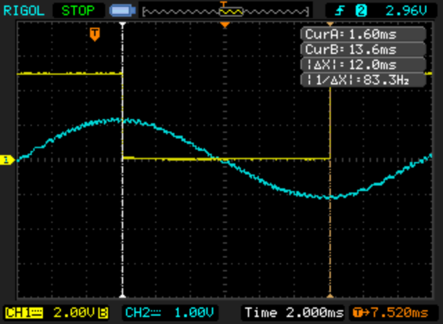
You see, that blue line is the BEMF and it is always at 90 degrees after rotor position, that is why on motor.c, hall sensors signal transition:
case 2:
ui8_motor_rotor_absolute_angle = (uint8_t) MOTOR_ROTOR_ANGLE_90;
In the case of my motor, it is at 90 + 5 degrees. So MOTOR_ROTOR_OFFSET_ANGLE = 5.

I think that maybe or motor is at 10 of 15 degrees and you should adjust instead MOTOR_ROTOR_OFFSET_ANGLE, because FOC will then be at 180 degrees, while adjusting MOTOR_ROTOR_ANGLE_STARTUP only, means your FOC will not be at 180 degrees...
I want to delete from the firmware the MOTOR_ROTOR_ANGLE_STARTUP, as I think that just like FOC, it is always at a fixed angle value. What may differ is the motor MOTOR_ROTOR_OFFSET_ANGLE, that when well adjusted will make the best startup and best torque and efficiency with motor running.

Can you please verify??
 
I think you're having issues with this because the controller is not running any sort of FOC control scheme. I don't see how you can try and reference any sort of d,q point when there is no point where data from the controller is converted to a 2 axis coordinate.

Refer to this article discussing FOC vs sinusoidal commutation https://www.controleng.com/single-article/got-field-oriented-control-in-your-servosthis-article-includes-online-material/37ab28025a3dd3e9ab551567b510795a.html
 
lizardmech said:
I think you're having issues with this because the controller is not running any sort of FOC control scheme. I don't see how you can try and reference any sort of d,q point when there is no point where data from the controller is converted to a 2 axis coordinate.

Refer to this article discussing FOC vs sinusoidal commutation https://www.controleng.com/single-article/got-field-oriented-control-in-your-servosthis-article-includes-online-material/37ab28025a3dd3e9ab551567b510795a.html
lizardmech, I started this thread to discuss the developement of firmware for KT and BMSBattery motor controllers.

You are not welcome here. Please don't start again, leave and start a new thread to discuss that topic.

It is enough what you did on EUC forum. I will just ignore you.
 
Regen

Stancecoke, I was looking at regen. I looked at phase B current wave form and comparing always to rotor 90 degrees. I looked to motor and regen modes, with and without FOC enabled. I got the regen mode working in a way that I don't feel any more the vibrations and this makes me happy with my direct drive motor (finally!!). Unfortunately, I also had some temporary issue with the throttle signal from my torque sensor and I was in an hurry so I could not do a long ride for testing.

I did push the code to master branch, and the change was this:
Code:
// read here the phase B current: FOC Id current
        ui8_adc_id_current = UI8_ADC_MOTOR_PHASE_B_CURRENT;

        if (UI8_ADC_MOTOR_CURRENT > ui8_adc_motor_current_offset)
	{
          // motor mode
	  if (ui8_adc_id_current > ADC_PHASE_B_CURRENT_ZERO_AMPS_FOC_MAX) { ui8_angle_correction++; }
	  else if (ui8_adc_id_current < ADC_PHASE_B_CURRENT_ZERO_AMPS_FOC_MIN) { ui8_angle_correction--; }
	}
        else
	{
	  // regen mode
  	  if (ui8_adc_id_current > ADC_PHASE_B_CURRENT_ZERO_AMPS_FOC_MAX) { ui8_angle_correction--; }
  	  else if (ui8_adc_id_current < ADC_PHASE_B_CURRENT_ZERO_AMPS_FOC_MIN) { ui8_angle_correction++; }
	}

So, for what I saw on oscilloscope and what I expect, phase B current inverts / changes 180 degrees phase and we need to keep it at the same "FOC angle" of the 180 degrees, so we just need to invert the logic for increasing/decreasing the ui8_angle_correction.

The feeling on the torque when accelerating from startup is near the TSDZ2, I mean when using the same motor power (~ 750W) and the highest gear on my ebikes.

Programming header with the VCC from STLinkV2

I lost some time with an issue were my hall sensors were not working although the motor phases control were... until I saw that the voltage regulator was to much hot and I went to measure the VCC line and it was like at 2.5V instead of the 5V -- that was because I changed the connector of my STLinkV2 and was connecting also the VCC of it to the VCC on the controller (I think STLinkV2 has 3.3V while controller has 5V).
 
Back
Top