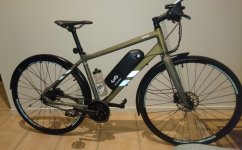
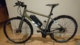
New "TSDZ2 Torque Sensor Central Motor"

Here you can see the options that users will be able to configure on our OpenSource firmware for TSDZ2:
- Different throttle modes:
-- torque sensor Human Power mode (torque * PAS)
-- torque sensor plain signal only
-- PAS mode but with starting up using torque sensor signal

- max pedal cadence value
- assist levels multiplication factor
- battery pack from 7S up to 14S, for indication of battery state of charge on LCD and also protection of battery undervoltage: firmware quickly stops drawing battery current when the VLC voltage is hit
- max battery current (controller max possible value if 16 amps)
- step rate of increasing PWM duty-cycle: will help to get a slow increase of motor torque and so protect the plastic blue gear
- tweaking motor max efficiency torque per amp (this may give only smaller improvement)
- support for 2 different LCDs: TSDZ2 LCDs and Kunteng LCD3 (LCD5 also) that is more complete like can show motor usage power in real time, battery voltage, etc.

None of this features are not yet implemented on our firmware for TSDZ2 but all of that is implemented already for our firmware running on Kunteng motor controllers and should be very easy to put working on TSDZ2 -- here is the configuration file and the options:

Code:
/*
 * TongSheng TSDZ2 motor controller firmware/
 *
 * Copyright (C) Casainho, 2018.
 *
 * Released under the GPL License, Version 3
 */

#ifndef CONFIG_H_
#define CONFIG_H_

// This file is the firmware configuration for the TSDZ2 motor controller,
// to run the 2 different available motors of 36V or 48V motor,
// and from 24V battery (7S) up to 52V battery pack (14S).

// *************************************************************************** //
// THROTTLE
//
// choose between following modes. You can choose for instance TORQUE_SENSOR_AND_THROTTLE and if you have
// throttle connected, the output signal used to control the motor will be the max value of both torque sensor or throttle
#define EBIKE_THROTTLE_TYPE	EBIKE_THROTTLE_TYPE_TORQUE_SENSOR_AND_THROTTLE
//#define EBIKE_THROTTLE_TYPE	EBIKE_THROTTLE_TYPE_PAS_AND_THROTTLE
//#define EBIKE_THROTTLE_TYPE EBIKE_THROTTLE_TYPE_THROTTLE_ONLY

// next, choose one of the both (only apply to throttle and/or PAS)
//#define EBIKE_THROTTLE_TYPE_THROTTLE_PAS_PWM_DUTY_CYCLE // direct PWM duty_cycle control, important for developers
#define EBIKE_THROTTLE_TYPE_THROTTLE_PAS_CURRENT_SPEED // control using motor current/torque and/or wheel speed

// next, if enabled, output of torque sensor algorithm is the human power (torque * cadence) other way will be the same as the torque signal
// (only apply to torque sensor)
#define EBIKE_THROTTLE_TYPE_TORQUE_SENSOR_HUMAN_POWER

// PAS configurations
// MAX cadence, where the output value of PAS processiing will be the max value
#define PAS_MAX_CADENCE_RPM 	90
// *************************************************************************** //

// *************************************************************************** //
// LCD
// the firmware supports the original LCD and the more complete Kunteng LCD3 and LCD5
#define LCD_TYPE LCD_TYPE_TSDZ2
#define LCD_TYPE LCD_TYPE_KUNTENG // shows battery voltage, motor real time usage power, etc

// you can tune LCD assist level
#define ASSIST_LEVEL_0			0.00
#define ASSIST_LEVEL_1 			0.44
#define ASSIST_LEVEL_2 			0.66
#define ASSIST_LEVEL_3 			1.00
#define ASSIST_LEVEL_4 			1.5
#define ASSIST_LEVEL_5 			2.25
// *************************************************************************** //

// *************************************************************************** //
// BATTERY
// Choose your battery pack voltage

// the cells number can be a custom value from 7S up to 14S, choose the value of your battery pack
#define BATTERY_LI_ION_CELLS_NUMBER	 7 // 7S = 24V battery pack
//#define BATTERY_LI_ION_CELLS_NUMBER	10 // 10S = 36V battery pack
//#define BATTERY_LI_ION_CELLS_NUMBER	13 // 13S = 48V battery pack
//#define BATTERY_LI_ION_CELLS_NUMBER 14 // 14S = 52V battery pack

// This is the current that motor will draw from the battery
// Higher value will give higher torque and the limit of the controller is 16 amps
#define ADC_BATTERY_CURRENT_MAX		224 // (14 ADC bits step per 1 amp) so, 224 for 16 amps

// Considering the follow voltage values for each li-ion battery cell
// State of charge 		| voltage
#define LI_ION_CELL_VOLTS_100 	4.06 // this value is used to help finding the battery SOC
#define LI_ION_CELL_VOLTS_80 		3.93 // this value is used to help finding the battery SOC
#define LI_ION_CELL_VOLTS_60 		3.78 // this value is used to help finding the battery SOC
#define LI_ION_CELL_VOLTS_40 		3.60 // this value is used to help finding the battery SOC
#define LI_ION_CELL_VOLTS_20 		3.38 // this value is used to help finding the battery SOC
#define LI_ION_CELL_VOLTS_10 		3.25 // this value is used to help finding the battery SOC
#define LI_ION_CELL_VOLTS_0 		3.00 // this value is used to help finding the battery SOC and is the minimum value after which the firmware don't ask more current to battery, to run the motor
// *************************************************************************** //

// *************************************************************************** //
// MOTOR CONTROLLER

// Choose PWM ramp up/down step (higher value will make the motor acceleration slower)
//
// For a 24V battery, 25 for ramp up seems ok. For an higher voltage battery, this values should be higher
#define PWM_DUTY_CYCLE_RAMP_UP_INVERSE_STEP	25
#define PWM_DUTY_CYCLE_RAMP_DOWN_INVERSE_STEP	10
// *************************************************************************** //

// *************************************************************************** //
// MOTOR

// Choose some parameters for your motor (if you don't know, just keep the following original values because they should work ok)
//
// This value should be near 0.
// You can try to tune with the whell on the air, full throttle and look at batttery current: adjust for lower battery current
#define MOTOR_ROTOR_OFFSET_ANGLE 0

// This value is ERPS speed after which a transition happens from sinewave no interpolation to have
// interpolation 60 degrees and must be found experimentally but a value of 25 may be good
#define MOTOR_ROTOR_ERPS_START_INTERPOLATION_60_DEGREES 25
// *************************************************************************** //

#endif /* CONFIG_H_ */
 
Hi Casainho,
Once again, thanks for the work you are doing on this project. I can see it being very useful to many people.

One thing I have never fully understood about these mid drive motors is why there needs to be a maximum limit on pedal cadence built into the controller.
Is it to protect the motor from overspeeding? This would make sense, as the motor rpm and pedaling cadence are linked by the gear ratio between the motor and the output gear that drives the chainring.
In that case, why not select a safe maximum rpm for the motor, work out the cadence that gives that motor speed, and simply build that into the firmware as a limit?

What advantage would there be in limiting the maximum cadence at which motor assist is applied to a value lower than that? And if there is no advantage, then why give an option to alter that figure in the firmware..

Possibly I am missing something here, but it just seems to me that there is no need for a selectable value.
 
Let's learn together!!

You need to link/map PAS value to motor current/torque. Let's say that max configured current is the 16 amps. So, 0 cadence will be 0 amps and max configured cadence will be max configured current, in this case the 16 amps -- so we need o define max cadence, can't be un unknown value.

Drum said:
Hi Casainho,
Once again, thanks for the work you are doing on this project. I can see it being very useful to many people.

One thing I have never fully understood about these mid drive motors is why there needs to be a maximum limit on pedal cadence built into the controller.
Is it to protect the motor from overspeeding? This would make sense, as the motor rpm and pedaling cadence are linked by the gear ratio between the motor and the output gear that drives the chainring.
In that case, why not select a safe maximum rpm for the motor, work out the cadence that gives that motor speed, and simply build that into the firmware as a limit?

What advantage would there be in limiting the maximum cadence at which motor assist is applied to a value lower than that? And if there is no advantage, then why give an option to alter that figure in the firmware..

Possibly I am missing something here, but it just seems to me that there is no need for a selectable value.
 
Drum said:
Is it to protect the motor from overspeeding? This would make sense, as the motor rpm and pedaling cadence are linked by the gear ratio between the motor and the output gear that drives the chainring.
In that case, why not select a safe maximum rpm for the motor, work out the cadence that gives that motor speed, and simply build that into the firmware as a limit?

What advantage would there be in limiting the maximum cadence at which motor assist is applied to a value lower than that? And if there is no advantage, then why give an option to alter that figure in the firmware..
Also motor max RPM value must be controlled, in this case it is defined to be 520 ERPs or the FOC will probably start to fail and motor ask to much current, etc.

About cadence, let's say you limit to 60 which is a low value. Means that you would easily get max motor current assitance, it would be like run with full throttle almost all the time.
 
And the PAS cadence or human power, etc will be multiplied anyway by the LCD assist level.
 
The battery options sounds great Casainho. It will be nice to be able to use all of the 52v batteries, and also be able to use cheap 22v batteries in series and be able to ship them or take them on aircrafty. Tuning the pas would be nice too, it works pretty well for us though. I WAS hating on the lag between pas and throttle however now that I have been using the throttle as a clutch I can live with the lag. The bike shifts so much better now, I just push the throttle 1/4 of a second before pushing the shift lever and then release both at the same time. It works great :) There is even enough lag time to shift 2 gears at once.
 
Hi Casainho,
Ok, I had been assuming that the motor current (and therefore torque) would be primarily controlled by the torque applied to the pedals, and that cadence would have little effect.
So if cadence has a significant effect, then people who like to spin fast in lower gears can set the max cadence high, and people who like to work hard at lower cadence can set it lower, getting full torque at lower cadence, is that right?
When the max cadence figure is exceeded, what does the controller do? Remain at full current, cut power completely or something in between?
I know it is annoying riding a bike with a low max cadence up a hill, and you just want to spin a bit faster in the same gear but you don't get the full support anymore, and have to change up a gear and reduce cadence to get the full benefit from the motor.
 
John and Cecil said:
The battery options sounds great Casainho. It will be nice to be able to use all of the 52v batteries, and also be able to use cheap 22v batteries in series and be able to ship them or take them on aircrafty.
Forgot to mention this options:
// Considering the follow voltage values for each li-ion battery cell
// State of charge | voltage
#define LI_ION_CELL_VOLTS_100 4.06 // this value is used to help finding the battery SOC
#define LI_ION_CELL_VOLTS_80 3.93 // this value is used to help finding the battery SOC
#define LI_ION_CELL_VOLTS_60 3.78 // this value is used to help finding the battery SOC
#define LI_ION_CELL_VOLTS_40 3.60 // this value is used to help finding the battery SOC
#define LI_ION_CELL_VOLTS_20 3.38 // this value is used to help finding the battery SOC
#define LI_ION_CELL_VOLTS_10 3.25 // this value is used to help finding the battery SOC
#define LI_ION_CELL_VOLTS_0 3.00 // this value is used to help finding the battery SOC and is the minimum value after which the firmware don't ask more current to battery, to run the motor
That is the possibility for user, I would say a very tecnhical one, to tune each cell voltage and that can be relevant when preferring to deep discharge each cell to get an higher range for long tour or something, or the inverse, don't discharge to much each cell to preserve battery life.
 
John and Cecil said:
I WAS hating on the lag between pas and throttle however now that I have been using the throttle as a clutch I can live with the lag. The bike shifts so much better now, I just push the throttle 1/4 of a second before pushing the shift lever and then release both at the same time. It works great :) There is even enough lag time to shift 2 gears at once.
So if you prefer to use the throttle to make working a "clutch"/gear shift sensor, I can later implement on the firmware support for the Bafang gear shift sensor to be connected to the throttle wire and you will get the feature as in Bafang motors.
 
casainho said:
John and Cecil said:
The battery options sounds great Casainho. It will be nice to be able to use all of the 52v batteries, and also be able to use cheap 22v batteries in series and be able to ship them or take them on aircrafty.
Forgot to mention this options:
// Considering the follow voltage values for each li-ion battery cell
// State of charge | voltage
#define LI_ION_CELL_VOLTS_100 4.06 // this value is used to help finding the battery SOC
#define LI_ION_CELL_VOLTS_80 3.93 // this value is used to help finding the battery SOC
#define LI_ION_CELL_VOLTS_60 3.78 // this value is used to help finding the battery SOC
#define LI_ION_CELL_VOLTS_40 3.60 // this value is used to help finding the battery SOC
#define LI_ION_CELL_VOLTS_20 3.38 // this value is used to help finding the battery SOC
#define LI_ION_CELL_VOLTS_10 3.25 // this value is used to help finding the battery SOC
#define LI_ION_CELL_VOLTS_0 3.00 // this value is used to help finding the battery SOC and is the minimum value after which the firmware don't ask more current to battery, to run the motor
That is the possibility for user, I would say a very tecnhical one, to tune each cell voltage and that can be relevant when preferring to deep discharge each cell to get an higher range for long tour or something, or the inverse, don't discharge to much each cell to preserve battery life.
How much does this matter in reality?

I know from single cell applications by logging their discharge curve that soon as you go below certain battery-safe thresholds, there is barely any energy left. This is especially true for high current drain applications. The voltage just drops too quickly below safe operation levels. If you want more range you need to lower the load on the cells to maintain a higher safe voltage(and you can discharge them much further!). This is more convenient for the user as well. Otherwise you get to the point where the controller will constantly stop working instead of just lowering the assist level. There is no reason to discharge lower as the drawback(=killing your battery) for cycling 1km extra makes no sense.. Unless you have plenty of batteries on stock.

You could use an automatic pack size detection and limit the current as soon as it goes below safe threshold values(as you know the pack size, you should be able to calculate the safe values as well) and you could add a percentage value instead of voltages for people that want to discharge it less.

This is much simpeler for the user to understand. The discharge curve for many li-ion cells is very similar so you don't need to hard code voltages.
 
Drum said:
Hi Casainho,
Ok, I had been assuming that the motor current (and therefore torque) would be primarily controlled by the torque applied to the pedals, and that cadence would have little effect.
So if cadence has a significant effect, then people who like to spin fast in lower gears can set the max cadence high, and people who like to work hard at lower cadence can set it lower, getting full torque at lower cadence, is that right?
When the max cadence figure is exceeded, what does the controller do? Remain at full current, cut power completely or something in between?
I know it is annoying riding a bike with a low max cadence up a hill, and you just want to spin a bit faster in the same gear but you don't get the full support anymore, and have to change up a gear and reduce cadence to get the full benefit from the motor.
Interesting questions you put!! Let me show you the math that our firmware does for Kunteng motor controllers -- and I must say that was experienced riders that asked to be the math like this, for instance, I never heard of "human power" before this firmware development.

So, the very first thing to run on the ebike_app loop that controls the motor, this algorithm:

temp = ((float) torque_sensor_value) * LCD_assist_level ();
if (temp > 255) { temp = 255; }
That is the torque sensor signal value multiplied by the LCD assist level value. Also the final value of the multiplication is limited to be the max of 255, that is equivalent to our 100%.
This means that the force we do on the torque sensor can be amplified (or divided) depending on the assist level we choose on LCD and the configurations for the factor of each LCD assist level we did on config.h file.

On the next step, depending on the user configuration to use or not the "human power", the previous signal is multiplied by the pedal cadence:
#if defined (EBIKE_THROTTLE_TYPE_TORQUE_SENSOR_HUMAN_POWER)
// calc humam power on the crank using as input the pedal torque sensor value and pedal cadence
temp = (uint8_t) (temp * ((float) ((float) pas_cadence_rpm / ((float) PAS_MAX_CADENCE_RPM))));
#else
temp = (uint8_t) temp;
#endif
So, let's say user were doing max torque on pedal, the previous value would be 255 (100%). And the MAX configured pedal cadence is 80 but user were pedaling at 40, the final value after this step would be: 255 * (40/80) = 127; would be 127 which is equivalent of 50% of the signal.

And the final step, is to setup the target current value for the current controller:
target_current = (uint8_t) (map ((uint32_t) temp,
(uint32_t) 0, // min input value
(uint32_t) 255, // max input value
(uint32_t) 0, // min output battery current value
(uint32_t) 16)); // max output battery current value, 16 amps on TSDZ2
ebike_app_battery_set_current_max (target_current);
Here, we use "map" function that has the input the previous signal (including the min and max limits we desire) as also min and max for the output signal we want. The output signal we want is the current value and our max value is 16 for TSDZ2.
Assuming the previous value from the last step was 127 (50% because although user was doing max torque on pedals but at 50% of the cadence), the setup current value for the motor current controller will be 8 amps. So the user will be assisted from the motor, half of the max possible torque.

It is now clear?
 
fantasy2 said:
casainho said:
John and Cecil said:
The battery options sounds great Casainho. It will be nice to be able to use all of the 52v batteries, and also be able to use cheap 22v batteries in series and be able to ship them or take them on aircrafty.
Forgot to mention this options:
// Considering the follow voltage values for each li-ion battery cell
// State of charge | voltage
#define LI_ION_CELL_VOLTS_100 4.06 // this value is used to help finding the battery SOC
#define LI_ION_CELL_VOLTS_80 3.93 // this value is used to help finding the battery SOC
#define LI_ION_CELL_VOLTS_60 3.78 // this value is used to help finding the battery SOC
#define LI_ION_CELL_VOLTS_40 3.60 // this value is used to help finding the battery SOC
#define LI_ION_CELL_VOLTS_20 3.38 // this value is used to help finding the battery SOC
#define LI_ION_CELL_VOLTS_10 3.25 // this value is used to help finding the battery SOC
#define LI_ION_CELL_VOLTS_0 3.00 // this value is used to help finding the battery SOC and is the minimum value after which the firmware don't ask more current to battery, to run the motor
That is the possibility for user, I would say a very tecnhical one, to tune each cell voltage and that can be relevant when preferring to deep discharge each cell to get an higher range for long tour or something, or the inverse, don't discharge to much each cell to preserve battery life.
How much does this matter in reality?
I can't say because I am not experienced on this but this configurations were asked by users that seems experienced and that do different ebike builds, etc.

fantasy2 said:
If you want more range you need to lower the load on the cells to maintain a higher safe voltage(and you can discharge them much further!). This is more convenient for the user as well. Otherwise you get to the point where the controller will constantly stop working instead of just lowering the assist level.
What you suggest is the way our firmware is implemented and again it was asked be experienced users/testers to be like that.

1. You can lower the load on the cells be reducing the assist level on the LCD (that is what I do when my battery is low and I want to arrive home) (even on LCD3, you can even reducing further the value because there is a specific command to reduce the max current, like the 16 amps on TSDZ2 can be first reduced to something like in 10% steps: 90% 80% etc)

2. And as you suggest, our firmware never disables the controller, it only very quickly lowers the assist level when the battery low voltage get's hit.
Like when battery is low, at startup when asked battery current is high, you will get automatically lower assistance but after that you will continue to get assistance - this way we get most possible from the battery.
Anyone knows how TSDZ2 original firmware behaves on this situation of low battery??
 
Hi Again Casainho.
Yes, absolutely clear. Thanks for the detailed and lucid explanation.
I think for the type of tracks I ride I would be happier with just the "torque sensor value*LCD" value, so full motor torque could be applied even at lower cadence.
You say "depending on the user configuration to use or not the "human power"".. does this mean there will be a choice to use just the torque sensor*LCD value OR to multiply that by cadence % ? That would be ideal, as it would suit a wider range of riding styles and terrain.
 
Drum said:
Hi Again Casainho.
Yes, absolutely clear. Thanks for the detailed and lucid explanation.
I think for the type of tracks I ride I would be happier with just the "torque sensor value*LCD" value, so full motor torque could be applied even at lower cadence.
You say "depending on the user configuration to use or not the "human power"".. does this mean there will be a choice to use just the torque sensor*LCD value OR to multiply that by cadence % ? That would be ideal, as it would suit a wider range of riding styles and terrain.
Yes, the option is this one on config.h file and to disable, is just a matter of comment the line with "//" at his begin:
// next, if enabled, output of torque sensor algorithm is the human power (torque * cadence) other way will be the same as the torque signal
// (only apply to torque sensor)
#define EBIKE_THROTTLE_TYPE_TORQUE_SENSOR_HUMAN_POWER

You see, that affects only this piece of the algorithm:
#if defined (EBIKE_THROTTLE_TYPE_TORQUE_SENSOR_HUMAN_POWER)
// calc humam power on the crank using as input the pedal torque sensor value and pedal cadence
temp = (uint8_t) (temp * ((float) ((float) pas_cadence_rpm / ((float) PAS_MAX_CADENCE_RPM))));
#else
temp = (uint8_t) temp;
#endif
 
Yet another tsdz2 build...

Did my first test ride in the lounge room tonight. Just enough to feel the motor kick in with a little pressure on the pedals. So all looks ok at this stage. Will take for a proper spin tomorrow if weather ok.

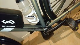
Am pleased I could still fit a water bottle to the seat tube. Drilled an additional hole in the lower battery mount to fit to the lower bottle cage mount. Will insert two extra rivnuts higher up the down tube to ensure a solid connection (4 x M5 rivnuts altogether).

The bike came with Alfine 11 speed IGH and Gates belt drive, but had to revert to chain drive due to Belt line with the TSDZ2 being about 10mm too far outboard (54mm). Could be fixed with a Rohloff IGH which has 54mm beltline, or possibly some Gates front and rear Di2 offset belt sprockets. That will be project stage 2.

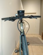
ebike_1.JPG

ebike_2.JPG

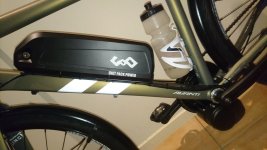
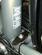
Power cable from battery enters on the side of the battery mount for neatness. XT60 connector from battery to motor hidden in the lower part of the battery mount.

ebike_3.JPG

Battery 52v 14Ah Sanyo cells (14s4p)
Motor 52v 750w
ebike_4.JPG

ebike_5.JPG

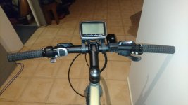
Have fitted the throttle, but will likely remove that once I have completed testing process.
ebike_6.JPG

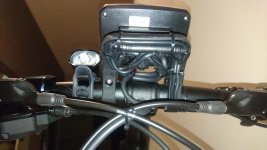
Excess lead for motor controller, throttle and remote controller switch coiled under display bracket.
Will replace the headlight with one powered from the main battery.
ebike_8.JPG

ebike_7.JPG

This 64yo granny feeling pleased so far. It has been a steep 5 months learning curve, but this site and topic has been a huge help. Thanks all.
Cheers Emma
 
emr said:
Battery 52v 14Ah Sanyo cells (14s4p)
Motor 52v 750w
Nice build and thaks for sharing!!

The motor runs with the power you apply to it, and in this case is: 52v * 16 amps = 832w and not the 750w you do refer.
The controller is setup on factory to provide the 16 amps.
 
casainho said:
emr said:
Battery 52v 14Ah Sanyo cells (14s4p)
Motor 52v 750w
Nice build and thaks for sharing!!

The motor runs with the power you apply to it, and in this case is: 52v * 16 amps = 832w and not the 750w you do refer.
The controller is setup on factory to provide the 16 amps.

Thanks for the info casainho. The motor was advertised as 750w, but am happy to have a little extra to play with.
 
emr said:
Yet another tsdz2 build...
Very nice build!

You might want to keep the throttle Emma, at least until someone (Casainho :) ) implements a way to use a gear sensor. When you push the throttle (at least on my motor) when pedaling in pas mode the motor will immediately shut off for a second or so until the throttle kicks in. I have found this lag time actually works well as a clutch, and I push the throttle about 1/4 of a second or so before I push the gear shifter and then release the two at the same time. It makes for a fairly fast controlled shift which is proving to be very useful, especially when you reach an incline at speed and you need to go all the way from 8th gear to 1st gear while pedaling up the incline.

I am glad to see the 52v batteries can be used all the way to max charge with the 52v controller. Our 48v version won't work when the battery is above 55.8v, I am looking forward to updating our firmware or upgrading to a 52v controller to utilize 52v batteries. The extra power is really nice when climbing. :)
 
Too bad they didn't introduce some sort of on/off style throttle on the XH18 display, it's already got a thumb grip. They could have made a toggle mode by holding some say the "i" button for a certain amount of time.
 
casainho said:
emr said:
Battery 52v 14Ah Sanyo cells (14s4p)
Motor 52v 750w
Nice build and thaks for sharing!!

The motor runs with the power you apply to it, and in this case is: 52v * 16 amps = 832w and not the 750w you do refer.
The controller is setup on factory to provide the 16 amps.

Casainho,

Thanks for all your work on this. I'm looking at getting this motor.
Does the motor have a temperature sensor, that can dial back the power when it is getting too hot?
How hard is it to reprogram, is there a serial port or something like that?
I really like the idea of adding gear sensor functionality, and the ability to dial back acceleration to save blue gear wear
 
wpenner said:
Does the motor have a temperature sensor, that can dial back the power when it is getting too hot?
How hard is it to reprogram, is there a serial port or something like that?
I really like the idea of adding gear sensor functionality, and the ability to dial back acceleration to save blue gear wear
Motor don't has any temperature sensor.
I also think there is no way to measure mosfets temperature.

Yes, it has UART. See more details, including programming, development tools and source code of current firmware here: https://opensourceebikefirmware.bitbucket.io/development_tsdz2/
And please join our efforts on developement!!
 
emr said:
Yet another tsdz2 build...
Cheers Emma
Cool bike and nice finishing job.
Drove my first 100 km today and very satisfied.
I'm sure you will like yours too.
 
casainho said:
emr said:
Battery 52v 14Ah Sanyo cells (14s4p)
Motor 52v 750w
Nice build and thaks for sharing!!

The motor runs with the power you apply to it, and in this case is: 52v * 16 amps = 832w and not the 750w you do refer.
The controller is setup on factory to provide the 16 amps.

Hi,..this actually depends, FYI. We program then up to 18a depending... Even though the power can go over 750w, the 750w is a good continuous rating for the motor, because anything higher than that is definitely peak/burst with this motor...
 
eyebyesickle said:
casainho said:
emr said:
Battery 52v 14Ah Sanyo cells (14s4p)
Motor 52v 750w
Nice build and thaks for sharing!!

The motor runs with the power you apply to it, and in this case is: 52v * 16 amps = 832w and not the 750w you do refer.
The controller is setup on factory to provide the 16 amps.

Hi,..this actually depends, FYI. We program then up to 18a depending... Even though the power can go over 750w, the 750w is a good continuous rating for the motor, because anything higher than that is definitely peak/burst with this motor...
Thanks.

I think the controller limit can be 72V (19S) if the input capacitors of 60V are changed to higher voltage.
The mosfet driver IC can handle 200V and the ICs step down converters to convert the 5V and 12V, the XL7005, can handle max of 80V and so this is the limit after the capacitors.

Don't know if motor could handle the 1.25KW: 72V * 18A.
 
emr said:
Yet another tsdz2 build...
Battery 52v 14Ah Sanyo cells (14s4p)
Motor 52v 750w

First test ride on the road today. Only about 30km. Motor met my expectations, so wasn't disappointed. I did find I liked 'Turbo 'mode best when on roads or clear cycleways. 'Eco' or 'Tour' was good for busy areas and shared pedestrian zones.

Seems to cruise on flat roads at 38kph or 40kph fairly easily (not too much effort from me). Using standard front sprocket and 20 tooth rear on Shimano Alfine 11 speed IGH. Short but steep climbs (18%) where I would normally be working hard, were a one handed ride today. Even climbed a short driveway seated that must be 25% or more, that was previously a big standing effort on a mountain bike and only just achievable.

Will see how the 'Blue' gear stands up to this workload, but have the bronze gear ready if (when) it fails.

The IGH seems to work well with the mid drive motor, as one can change one or more gears while the gear train is not moving, which avoids any crunching of sprockets that might occur if too much power is applied as the gear change is taking place. One still needs to back off the pedalling force when changing gears, to avoid undue stress on the IGH internals.
 
Back
Top