
Ok so I've been looking at building a new battery pack for a long time now and I really want to make an 8p13s 20amp discharge pack for my ebike. The only problem is I'm having a tough time coming up with a good cell layout for the space that I have. I have watched a lot of triangle pack videos and a lot of them are very different from one another and I have heard a lot of bad things about most of them due to poor designs resulting in uneven series discharging. Micha tolls triangle pack build here (https://www.youtube.com/watch?v=clawhNsORts) has been recommended to me multiple times where he connects one row of cells to another by using "jumper leads". The problem, however, is that all of the jumpers used are different sizes from one another. example (https://imgur.com/a/Q7vYldv) or is it really a problem at all?
Now if I'm right here, different length wires will have different resistance values, so over time, some cells in parallel will have different charge rates, right? Or is the effect too small to even outlast the life of the cells anyway?
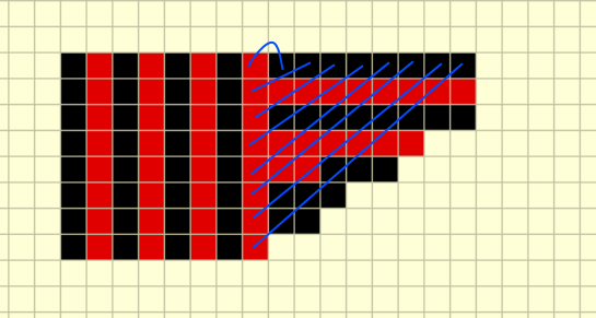
One idea I've thought of is just to connect one set of cells to another using all the same size jumpers with no nickel in between
(poor example: https://imgur.com/a/BbXhxCr) "all blue lines indicated equal sized silicon wire connections"
With this method, all the cells are connected by the same length and size of wire so there should be no noticeable difference in the resistance values. Will this work or should another method be attempted? Sorry if my explanation is poor, I just wanted to get some expert opinions or ideas on this idea as I want to do this right the first time. Thanks again.
Now if I'm right here, different length wires will have different resistance values, so over time, some cells in parallel will have different charge rates, right? Or is the effect too small to even outlast the life of the cells anyway?
One idea I've thought of is just to connect one set of cells to another using all the same size jumpers with no nickel in between
(poor example: https://imgur.com/a/BbXhxCr) "all blue lines indicated equal sized silicon wire connections"
With this method, all the cells are connected by the same length and size of wire so there should be no noticeable difference in the resistance values. Will this work or should another method be attempted? Sorry if my explanation is poor, I just wanted to get some expert opinions or ideas on this idea as I want to do this right the first time. Thanks again.
.jpg")