Reading data from my sabvoton controller

I don't have a reverse wire, So I m sending from the arduino the HEX code that change motor direction as the PC software does, it works just fine and I can reverse the motor direction by a switch, but as I turn the controller off and restart it, the switch doesn't work anymore, as if there is no communication between the arduino and the controller.

any ideas ?
 
i think the adruino needs to send the start code to the controller on startup.

and maybe you can add the reverse wire to the controller. I map out the wireing on my controller in this post:
https://endless-sphere.com/forums/viewtopic.php?f=30&t=56378&start=25#p1337210

hope this helps
 
I had a couple people message me for source code to the dashboard. Unfortunately, I lost it in an HDD crash.

I ended up getting rid of the "street legal" set up I had, and converting it to a bicycle. I wanted to make sure I would be able to comply with my local legal compliance of an "electric assist bicycle". So I needed to have a way to limit power to 750W, and limit top speed to 25 mph. I looked into the 3-speed switch on the controller, but I was unable to get it to work. Instead, I remembered being able to read data from the controller, and wanted to see if I could also write configuration data and program max current, and motor speed limit on the fly with an arduino. I believe I was successful, so I thought I would document it here in case anyone else is looking for something similar.

I started from the Arduino sketch in the OP. I just got it to a functional state. It could be MUCH cleaner, possibly using a Modbus library like this (https://playground.arduino.cc/Code/ModbusMaster/) instead of sending the raw bytes. However, for my application, it was fine.

I started by capturing the serial data by using an application called "Device Monitoring Studio" (https://www.hhdsoftware.com/device-monitoring-studio) in a 14 day trial period. From there, I was able to determine the following registers:
Motor Speed Limit: 0x0A4C
Rated DC Current: 0x09F7

The format for writing registers is similar to the format to the read data sketch in the OP.
Byte 1: 0x01 (address of controller)
Byte 2: 0x06 (write single register)
Bytes 3-4: Register Address
Bytes 5-6: Data
Bytes 7-8: CRC

For example, to set the motor speed limit to 100%, I wrote
01 06 0A 4C 00 64 4A 2E

The last two bytes are a kind of check to ensure data integrity. They can be obtained either by capturing the data, using an online CRC calculator, or generating them on the fly on the Arduino. I was super lazy, so I just used this online calculator: https://www.lammertbies.nl/comm/info/crc-calculation.html (Use CRC-17 (Modbus)) This calculator gives the bytes in reverse order. For example, it is says 0x4B37, byte 7 is 0x37, byte 8 is 0x4B.

With that, I was able to modify the original sketch to write the correct registers. Note: you need to run the enable_data function before the Sabvoton controller will allow you to write other registers.

I'll attach my sketch, but again, don't judge me too much! I used the switch from my rear brake lever to signal the Arduino when I want to switch modes. It requires 5 ON/OFF cycles within a few seconds, and then it will send the appropriate commands to the Sabvoton controller to switch modes. Works pretty well so far. I am powering the Arduino off of the 5V present on the Sabvoton controller USB connector, so I am using a low-power library to minimize current draw.
 

Attachments

  • Sabvoton_Legal_Switch_3.zip
    1.7 KB · Views: 205
Manny said:
for my Aprillia project https://endless-sphere.com/forums/viewtopic.php?f=12&t=83316 I want to read data from my sabvoton svmc96080 controller.

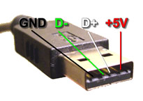
the usb connector on the sabvoton is not USB, luckily its just serial.

the original "programming cable" is a usb to serial converter with a usb connctor on the other end.

5IOnM.jpg


the +5v and gnd are in the same place, the D+ is the controller Tx and the D- is the controller Rx.

the communication uses the modbus protocol @ 19200 baudrate.

the PC software sends a code to write a register twice(just to be sure i guess) to start the communication. without this when requesting data all the data will be zero.

after the start code the PC software requests the same data continuously.

the data requested is the info you see on the main screen of the PC software.
I know what most of the data represents, some is still unknown.

I made a simple and crude ardino sketch that reads the data and sends the battery voltage to the arduino serial terminal. this code needs work. it is not fault tolerant it doesn't check the CRC on the incoming data. For my project I need to combine this code and the stepper motor code, and I like to do battery state of charge tracking to display on the dial.

the .xlsx file is all i know at the moment.

Hey Manny

How did you figure out what the start and data request codes were?

Thanks
 
I now have a relatively mature arduino sketch with which you can read and write arbitrary registers, I have also implemented a command to "play through" multiple values ​​and a command to output entire register areas.

If anyone is interested, here it comes:
https://github.com/slothorpe/Sabvot.../blob/master/SabvotonCommandlineInterface.ino

A typical session looks like this:
https://github.com/slothorpe/SabvotonCommandLineInterface/blob/master/CmdLine.png

And here's the list of registers I've identified so far:
https://github.com/slothorpe/SabvotonCommandLineInterface/blob/master/SabvotonRegister.xlsx

Maybe it helps someone ...
 
I will make some updates of the sketch, but the adress remains, so if you want to use it, look eventually for a new version.
maybe I put i on GitHub later.
 
Hi everyone,

does anyone know if the protocol on USB RX/TX is the same as on the Sabvoton's LCDs connector (that with 5 wires (+, ignition, -, RX, TX))?

I'm asking, because I bought Sabvoton without LCD wires (but with regular Sabvoton's LCD) and I wonder if I could "cheat" and hook it on USB wires.
 
HI Guy's,

This is really awesome work.

Can I please please encourage you to use git hub, at the moment the links slothorpe has put up are not accessible.

I just used this guide to setup the two repositories I have shared in this post. I used git before, I found this guide just seemed to "click" for me.

https://www.atlassian.com/git/tutorials/setting-up-a-repository

I've forked a number of repositories for the "Smart BMS" interface. It looks like much of it is the same constructs as you are using for the read/write on the Sabvton controllers. The code "bres55" has written is the most "modular" format for building a universal interface that could be used for both controllers and BMS's.

I have designed a board / hat for the MegaPro with 4 opto isolated serial interfaces that uses low quiescent drain regulators to interface to 3 BMS. The board is powered separately from the main packs and this combined with the low drain regulators will ensure the packs don't over-discharge.

I just made a repo here for the boards eagle files.

https://github.com/flashtel/Mega_Opto

View attachment 3

After I found this thread I've added a 4th for my Sabvaton to use with the code you have created.. In addition I have include interface port for the wiegand based protocol to connect to an RFID reader.

View attachment 2

This is my modified version of the "bress55" code, I've changed the "MySerial" definition to a reference that can be switched in the software routine between the various opto coupled serial interfaces.

https://github.com/flashtel/Smart-BMS-arduino-Reader/commit/7fd29a2101cc1a516ed5a2d96e6c925851cc4816


My initial intention was to have an 125khz RFID ring, that would be used to "Arm" the bike after checking each of the 3 Battery Packs for charge state and bringing them online. If I can incorporate the code you have developed, I can extend that to "Arming" into a specific controller configuration.

Screen Shot 2020-01-02 at 2.57.19 am.png

ie 2 RFID key's one for "Offroad / Monster" mode and another for "OnRoad /Legal Compliant Mode".

In the Mega_Opto library I've added an I2C interface for a 0802 LCD with 3 buttons. I don't like having "large" displays on the bike. It is as small and discrete as I could make it.

I have ordered 5 boards and I have Pick n Place machine here it, takes me literally 5 minutes to make additional boards once I have the setup, all the components are low cost.

If you want one PM me.

This is what I am going to power the "Managment Board / Mega_Opto" with.

Thanks Paul

 
Btw. something else:

I am currently developing a more intelligent control for the speedometer for my scooter, which will include the Sabvoton data (e.g. current, status, temperatures) and at the same time set the parameters depending on the speed level. The whole thing is based on an Arduino Mega, which then communicates with the Sabvoton via Modbus and simultaneously evaluates the other data of the scooter.

It then occupies the "USB" port of the Sabvoton, which, as you know, is only a simple serial interface with TTL level, so you can no longer use the original Bluetooth stick.

So I had the idea to include a Bluetooth adapter ... I analyzed the original Bluetooth stick a bit more closely ... and was really surprised:
This is not a simple Bluetooth serial converter, but a microcontroller that even speaks the Modbus protocol in the direction of Sabvonton, the APP only calls up the data ...

My solution now is, that I have integrated a stupid HM-05 Bluetooth - serial converter, so that I can not configure the controller with the mobile app but at least with the PC program via Bluetooth ...

The next step is that I will build my own speedometer with an intelligent TFT display (Nexion), unfortunately I am not the hero when it comes to graphic design ...
 
slothorpe said:
My solution now is, that I have integrated a stupid HM-05 Bluetooth - serial converter, so that I can not configure the controller with the mobile app but at least with the PC program via Bluetooth ...

If you don't want to implement your own Modbus RTU wrapper, you can also try to use the old SVMC app for Android (buggy as hell BTW). If you manage to make it work on your phone, there's plenty options to play with, but not all. Sabvoton used to include this kind of (regular) BT module in the past, right now they switched to BLE micro and developed a new app.

You can PM me if you need help with the old apk, I may have a modded version somewhere on hdd.
 
Manny said:
phase current is easy if your not using the flux weakening. if your using that you need to do some calculation between the "Torque current fbk" and the "Weaken current fbk". there is no readout on the pc software for the battery current :( hopefully it is some were in the data. hard to test on the workbench.

Any idea how to calculate the actual phase current out of „Torque current fbk“ ? Can‘t really see, what this parameter means, it goes between something - and + while running.
 
I’m trying to connect using an Arduino Uno and SoftwareSerial(2, 3) to replace Serial3. Only response so far is "couldn't send startseq, please connect to Sabvoto controller and restart/reset.” We tried both with and without the three pin connector on the Sabvoton connected, but no luck... Does anyone know what is happening and how to fix it?

Edit: We are using the SabvotonCommandLineInterface to read the data from the controller
 
The first thing I would check is if it is a "real" sabvoton, or one of the various clones *named* sabvoton. If it's not actually using (the correct version(s)) of sabvoton firmware, it probably wont' respond to external communication as expected.
 
First of all, thanks for your quick reply. How do i know if it is a genuine Sabvoton or a copy? I assumed it was genuine because the MQCON app works just as intended.
 
I don't know. I only know that there are multiple companies (including at least one calling itself "MQCON") selling things that have that name in their ads, but whose products have significant differences from each other, and whose software doesnt' all work with each other's stuff, or meet the specifications of each other's ads, etc. (and that some of them don't have nearly the quality of some of the others, and perhaps none of the originals, based on reports here on ES since the original company went out of business).


If the MQCON app works, you may have to find out how it communicates, to see if you have to update the commands sent by the method you're using to match the working method the app uses.
 
Has anyone successfully connected an esp8266 (nodemcu board) or Arduino Uno to the sabvoton controller?
My problem right now is, that the Uno only has one serial port, but the software on github posted by "slothorpe" uses two. One for communication with the controller and one for communicating with the PC.
Also what pins do I need to connect the controller to the Arduino? Straight from the controller USB or do I need to use the dongle?
 
just found this thread its been an interesting read, when i get my controller in the bike i may have to play along, especially as i could do with a low power/speed mode on road....

problem i'm hitting is my controller (ml7260, ml60?) didnt come with a usb cable, the 8 pin mini din socket isnt fitted, but i *think* serial and maybe 'can' are hidden in the 30 pin connector, problem, i cant find a pinout diagram for the 30 pin connector.....
 
Manny said:
I made a simple and crude ardino sketch that reads the data and sends the battery voltage to the arduino serial terminal. this code needs work. it is not fault tolerant it doesn't check the CRC on the incoming data. For my project I need to combine this code and the stepper motor code, and I like to do battery state of charge tracking to display on the dial.

the .xlsx file is all i know at the moment.


NOOOOOOOOOOOOOO! the code is gone lol, i'm just trying to do something like this with one of the clones, i soldered on a usb/ttl that i have a boxful of from my arduino bits but i'm not seeing any data flow from the controllers rx/tx, in fact they dont even seem 'right' as wired either way i get a rx light and tx light illuminated on the dongle, which usually only happens with data flowing. i dont know if my cheaper clone has firmware that actually uses the rx/tx pins marked on the pcb.
 
Hi everyone,

does anyone know if the protocol on USB RX/TX is the same as on the Sabvoton's LCDs connector (that with 5 wires (+, ignition, -, RX, TX))?

I'm asking, because I bought Sabvoton without LCD wires (but with regular Sabvoton's LCD) and I wonder if I could "cheat" and hook it on USB wires.
Hi just curious if you ended up trying this ,i think everyone has thought about it ,but didnt want to risk a controller and lcd ?
 
Back
Top