Improving original firmware - TongSheng TSDZ2 mid drive motor

hurzhurz said:
I forgot to mention, I already tried without the LCD. Didn't chance much.
The weird behavior of it could be a side effect of a broken ground or backfeed problem... have to check...

I had a quick look at the brake code.
I guess $6b is used as a counter to debounce the input and the effective state is saved in $92 bit #4. Maybe you can try this one out?

Yeah, cadence looks hard... I already tried to understand it (that's why I said something about direction detection).
I had the hope it is somewhat similar to the speed...
Great!! saw your comments on break code and it seems to make sense to me.

I hope to test today $6b bit #4 for brake state.

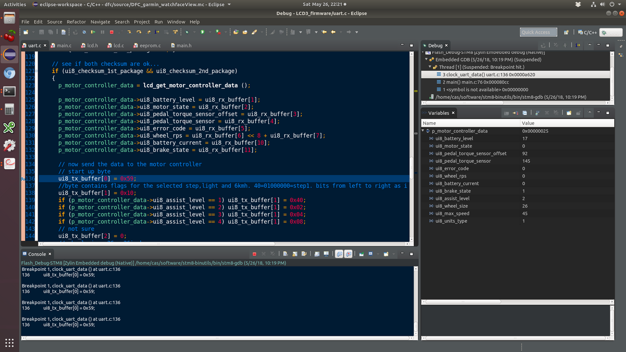
I am also ready to test our custom package on UART. You can implement it and I will test.

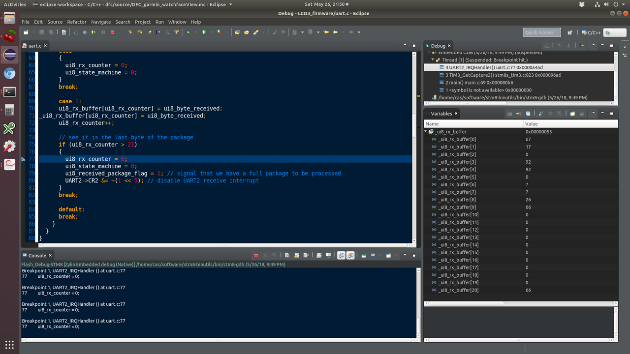
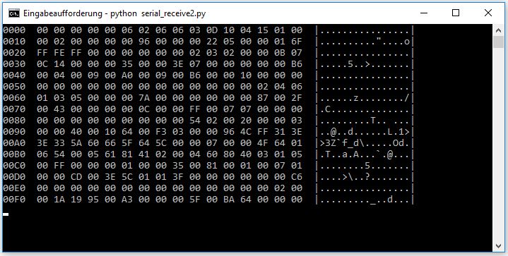
Also, for some reason, I always see checksum of the original package as 0...!!! I already verified and debugged my code but it seems correct.
 
See for yourself :)

[youtube]lMkyktJeY4M[/youtube]

$92 value:
// 64 no brake; motor stopped, all stopped
// 80 brake
 
Ok, so I have modified the firmware with the custom packet/message to send the current in the first data-byte and the brake-flag in bit #0 of the second data-byte.
The other 8 data-bytes are just 00.

Do you mean your LCD3 code regarding the checksum?
One single possible error:
line 308: if (ui8_rx_counter > 9)
I think ui8_rx_counter should be == 9 at this step. So try >=9.
But I'm not sure if this would cause the problem...

EDIT: just saw your update, great! :)
 

Attachments

  • TSDZ2_original_firmware-Flexible_modified-3.zip
    12.4 KB · Views: 81
hurzhurz said:
Ok, so I have modified the firmware with the custom packet/message to send the current in the first data-byte and the brake-flag in bit #0 of the second data-byte.
The other 8 data-bytes are just 00.
Can you please update the sheet file?? Don't worry because I saved the previous version on github.

I really need to see and understand / review what you did, to understand how to implement on LCD and also to try change in the case it does not work or some reason.
 
Ok, I have added it to the bottom, but it's probably easier to read in the other sheet.
So, new code added beginning at 0xbc60 and changed the call to this address (like before).

The new packet/msg is 12 bytes long:
1= start-byte 0x42 (we can change it to something else if you want)
2-11= data-bytes, first is $1d/current, second contains brake flag. rest just zero.
12= checksum
 
Good!!

Being thinking that next thing to have is throttle value and that is important for debug a good working throttle.

And could the duty-cycle be relevant??

Also the eeprom values just to show to user the voltage values as also max current limit.

I agree the cadence is even the most relevant for now.

And I wish we could define in realtime the max current :)
 
hurzhurz said:
Well, we are not far away from just dumping the RAM to serial ;)
Hmm... well... maybe not the dumbest idea for finding stuff...
Let's see we could see in real time the RAM... would be fast to put assist level = 0, pedal and see where cadence changes :)
 
hurzhurz said:
Yeah, and by the way, I'm currently working on also receiving custom messages.
So, my idea is to implement memory read&write commands... I hope that should open pretty much any possibility
I am just trying you latest version but my tool can't flash hex files but only bin files. Can you please upload the bin file?
 
Sure, here it is: View attachment output.zip

You can use srec_cat to convert if needed. You just have to keep an eye on the offset.
Code:
srec_cat.exe input.hex -Intel -output output.bin -binary
srec_cat.exe input.bin -binary -output output.hex -Intel

I have also made a python script for easier patching.
It loads a hex file as a base and patches it with opcodes (copy&paste from spreadsheet) from simple text files with the target start address in the filename.
The result is saved as hex and/or bin file.
View attachment hex-patcher.zip
 
Here is a screenshot with the packet. I would say the 2nd start byte could be removed, but keeping the checksum of the 2nd package. I will look only for the first start package and read up to the end and verify each package against each checksum.

 
hurzhurz said:
So, motor didn't need much current and you didn't brake while you were taking the screenshot? ;)

Well, that would work for now, but when I'm successful with what I'm doing at the moment, you can't be sure that it will always be in that order...
For now I just tested brakes and it works.
 
And now a bit further on the code flow:

 
Ok, nice!

I have also made some progress.
I can now send a message to manipulate byte $4010 in the EEPROM by sending:
88 AF 37 = sets it to AF
88 EE 76 = sets it to EE

Though, as my motor has issues at the moment, I can't test if the original message from the LCD is still processed correctly.
Maybe you can test it for me?

You can see the code in this spreadsheet:
https://docs.google.com/spreadsheets/d/1Zd2CQJKm7IopjqLz5JxIgySIFSY2SehPrXzffIbaVwM/edit?usp=sharing

And I have also added the value of the EEPROM byte and the rx-buffer-size to the custom message for debugging.
 

Attachments

  • output.zip
    23.7 KB · Views: 54
hurzhurz said:
Though, as my motor has issues at the moment, I can't test if the original message from the LCD is still processed correctly.
Maybe you can test it for me?
Sorry, I wanted to finalize. I hope to test on next days.

After 2 days, I got it working and I finally can swap the TSDZ2 original LCD to KT LCD3. Many thanks to hurzhurz for improving the original firmware.

KT LCD3 showing the following data from TSDZ2 motor:
- battery voltage
- motor power in watts
- bicycle wheel speed
- motor assist level
- brakes state
- battery state of charge

[youtube]75Na5RDLZAk[/youtube]

The motor power is clearly going to zero when it should not, this is clearly an issue that I need to improve. For the calcs, I am using the same filtered and stable voltage we can can on LCD. I guess the only source of issues is the current value sent by the controller... maybe I am doing something wrong somewhere...

After, I want to start calc the motor used Wh for the current trip.
 
What is byte $4010 for??

By the way, I figured out how to get the wheel speed very well. And it uses units at MPH... maybe there is a flag we can send to controller and it will work in km/h. You can see my code on the LCD3 firmware sources.

hurzhurz said:
Ok, nice!

I have also made some progress.
I can now send a message to manipulate byte $4010 in the EEPROM by sending:
88 AF 37 = sets it to AF
88 EE 76 = sets it to EE

Though, as my motor has issues at the moment, I can't test if the original message from the LCD is still processed correctly.
Maybe you can test it for me?

You can see the code in this spreadsheet:
https://docs.google.com/spreadsheets/d/1Zd2CQJKm7IopjqLz5JxIgySIFSY2SehPrXzffIbaVwM/edit?usp=sharing

And I have also added the value of the EEPROM byte and the rx-buffer-size to the custom message for debugging.
 
About the current value... have you yet tried to just display the raw value from the controller?


$4010 was just because I wanted to test with an unused eeprom address. But I have achieved a bit more yesterday:
I can now send a write command to write a single byte at a given 16bit address anywhere, including ram, flash and eeprom.
And I do now fill the last few bytes of the custom message by looking up the desired memory addresses from the eeprom, e.g. if eeprom $4010-$4011 are "50 10", the message would contain the value of the "Port D input value register".
Next things I want to implement:
- reorganize the UART transmit routine to send more additional messages, but just if needed.
- send a acknowledge for the write command
- implement a memory read command
- (maybe) extend the write command to write multiple bytes at a time (up to 16 or so)


Can you explain the wheel speed thing in more detail?
I was very confident that the two bytes simply tell the time between two sensor trigger events (= one rotation).
 
hurzhurz said:
About the current value... have you yet tried to just display the raw value from the controller?

$4010 was just because I wanted to test with an unused eeprom address. But I have achieved a bit more yesterday:
I can now send a write command to write a single byte at a given 16bit address anywhere, including ram, flash and eeprom.
And I do now fill the last few bytes of the custom message by looking up the desired memory addresses from the eeprom, e.g. if eeprom $4010-$4011 are "50 10", the message would contain the value of the "Port D input value register".
Next things I want to implement:
- reorganize the UART transmit routine to send more additional messages, but just if needed.
- send a acknowledge for the write command
- implement a memory read command
- (maybe) extend the write command to write multiple bytes at a time (up to 16 or so)

Can you explain the wheel speed thing in more detail?
I was very confident that the two bytes simply tell the time between two sensor trigger events (= one rotation).

There are a few bits only on that 2 bytes:
p_motor_controller_data->ui16_wheel_inverse_rps = ((ui8_rx_buffer[7] << 6) & 192) + ((ui8_rx_buffer[6] >> 3) & 31);

And here the information about a stopped wheel:
// ui8_rx_buffer[7] & 4 set means wheel is stopped
if (ui8_rx_buffer[7] & 4) { p_motor_controller_data->ui8_motor_controller_state_2 |= 128; }
else { p_motor_controller_data->ui8_motor_controller_state_2 &= ~128; }

And here the speed value calculation. No implementation yet on LCD to select wheel size:
Code:
    // the value sent by the controller is for MPH and not KMH...
    // (1÷((controller_sent_time÷3600)÷wheel_perimeter)÷1.6)
    f_wheel_speed = 1.0 / (((float) motor_controller_data.ui16_wheel_inverse_rps * 1.6) / 7380);
    if (motor_controller_data.ui8_motor_controller_state_2 & 128)
      f_wheel_speed = 0;

The only big thing now, I think, is pedal cadence.

Wouldn't you prefer to be working on our own firmware written from the scratch??


casainho said:
I got motor power working and I am very happy!! Anyone interested installing KT LCD3 for the TSDZ2? If so, I can write a simple guide for the installation.

The motor pulls 950W (18 amps) with my 48V charged!! With a 52V battery, would pull over 1000W.

It is clear on the video when I am breaking (symbol active on LCD) and stopped pedal, as battery voltage decreases when motor power increases and wheel speed also increases :)

[youtube]bNXXfhM9N10[/youtube]


casainho said:
I did some quick tests on an accentuated climb.
Assist level 1: max around 6 amps
Assist level 2: max around 12 amps
Assist level 3: max around 18.4 amps
Assist level 4: max around 18.4 amps
 
I'm still not sure how you figured out it should be MPH/KPH dependent?

I think, with this line, you just decrease the speed resolution from 16bit to 8 bit (but in a reasonable way by selecting the most important bits to survive):
Code:
p_motor_controller_data->ui16_wheel_inverse_rps = ((ui8_rx_buffer[7] << 6) & 192) + ((ui8_rx_buffer[6] >> 3) & 31);
And of course, this has an influence on the conversion factor. By also eliminating the 3 least significant bits, you basically divide the value by 8.
As I told you earlier, I calculated one "unit" to be ~2ms. Multiplied by 8 is ~16ms. Which looks similar to 1.6, the conversion factor from MPH to KPH?


Yeah, finding the cadence register is a important goal (if it exists and the PAS is not just used as a "human does something, motor allowed to run" flag).
I'm doing this the other things as a preparation to have it easier to find and verify it.
... and it is fun to learn about opcodes and assembler... ;)


Sure, develop an own firmware from scratch sounds like a better idea then... but I can't contribute much as I have absolute no experience about the most important motor control stuff...
 
hurzhurz said:
I'm still not sure how you figured out it should be MPH/KPH dependent?

I think, with this line, you just decrease the speed resolution from 16bit to 8 bit (but in a reasonable way by selecting the most important bits to survive):
Code:
p_motor_controller_data->ui16_wheel_inverse_rps = ((ui8_rx_buffer[7] << 6) & 192) + ((ui8_rx_buffer[6] >> 3) & 31);
And of course, this has an influence on the conversion factor. By also eliminating the 3 least significant bits, you basically divide the value by 8.
As I told you earlier, I calculated one "unit" to be ~2ms. Multiplied by 8 is ~16ms. Which looks similar to 1.6, the conversion factor from MPH to KPH?


Yeah, finding the cadence register is a important goal (if it exists and the PAS is not just used as a "human does something, motor allowed to run" flag).
I'm doing this the other things as a preparation to have it easier to find and verify it.
... and it is fun to learn about opcodes and assembler... ;)


Sure, develop an own firmware from scratch sounds like a better idea then... but I can't contribute much as I have absolute no experience about the most important motor control stuff...
Well, I look at bits and tested to try figure out... and I tested the read value at different speeds and compared with another speed reader. In the end it was luck when I tried to see if was in MPH as I always expected to be in KMH. And that took me a lot of time, I almost did quit.

Well, if cadence is not available, then we should to it with our own firmware. Seems that your investment should definitively help us to understand if there are registers with cadence value or not.

This was my last state about developing the firmware. I need to continue by implementing the math calculations for FOC and figure out a way to test and validate. But I think I will advance a bit more the LCD firmware, at least I want to have Ah for each trip. Also I want to at least put that big array of original firmware on the spreadsheet and see the wave form, to compare to what I already implemented -- I already learned by looking at the original firmware, yeah, we have been learning a lot :)

[youtube]EonFwTk2cs8[/youtube]
 
I have now finished the memory read command.
Together with a python script that does reads in intervals and shows them , I think it is indeed helpful:
mem.jpg


For the cadence, I have maybe identified registers $04 and/or $18 (maybe identical).

And battery voltage could probably be read from $1f.
Though, I'm not yet sure about the conversion factor... not enough datapoints as my lab bench power supply is capable of just 30V.

If you want to check that, I have included these 3 registers in the custom message as data-bytes 3 to 5.
And you can define 6-10 in the eeprom if you want.

Well, maybe I should now try to fix my motor/controller...
 

Attachments

  • output.zip
    24.3 KB · Views: 49
hurzhurz said:
I have now finished the memory read command.
Together with a python script that does reads in intervals and shows them , I think it is indeed helpful:
mem.jpg


For the cadence, I have maybe identified registers $04 and/or $18 (maybe identical).
Uauuu!! GREAT!!!

In a few days I will make some long rides and so I don't want to risk much with my motor... but I am really curious to try!!!

hurzhurz said:
And battery voltage could probably be read from $1f.
Though, I'm not yet sure about the conversion factor... not enough datapoints as my lab bench power supply is capable of just 30V.
I can try battery later. Anyway, I thin I know already the voltage resistor on the PCB so should be easy to calculate.

Please add also:
- %5b throttle value (I can show on LCD this value, for users/installer debug the throttle)
- %0c hall sensors state (only for ones trying to understand why the motor is not working, like you, you can verify by rotating by hand and know if they are working or not)
- PAS direction, if possible and will help to debug the PAS sensor
- PAS cadence, if possible and will help to debug the PAS sensor and having human power
[/quote]
 
Sure, no need to risk it beforehand ;)

If you want to try $5b / $0c (or anything else) before it is fixed included, just write this to the eeprom:
0x4010: "00 5b 00 0c"
Do you mean anything additional with PAS cadence then cadence candidates $04/$18?
By the way, I think they just shows something when rotated forward.


Oh, and I have opened my motor now.
I can say, the humming comes from the torque sensor or the coil.
When I unplug it and I measure constant 12.5V at the plug... I think that is not ideal?
You say something about 5V/20us pulses on your website...
Well, and there is an inductor that looks a little bit toasted as far as I can see through the "epoxy".
 
Back
Top