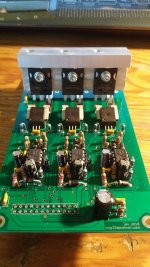
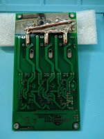
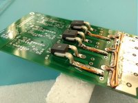
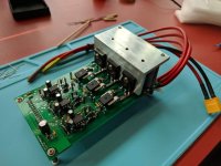
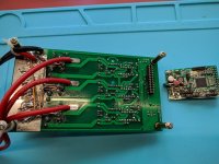
Power PCB for Lebowski Controller to be combined with Bobc's processor board

powerboard kit in the post too, sent this morning. Pm'd you all
 
I also had a rethink about the through hole parts. I found an equivalent smd cap to the big green cap off to the left in coles photo and bought some in. This should tidy it up quite a lot. Will maybe do similar with the other orange cap as they can be soldered with one end to the board and then adjoining wires can be lower and tidier. I think the zener can be done neatly enough as a through hole part. Just a massive shame that it really would benefit from a redesign to get it too use smd parts out of the gate.

I will try this stuff out on the future brain boards and if beta testers want to swap and are prepared to pay postage (to and fro) then I can do this for them (although its probably totally unnecessary and personally if it were me I wouldn't bother)

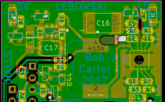
smd mod to lebowski board.png

to explain
green rectangle is 100nf 100v cap ac
red rectangle (on end tombstoning) is 4.7nf 100v Cr
grey rectangle is smd resistor 47kohm
black line is wire to the pad required.

Other thing is the zener already shown.

I think this will be a lot neater without requiring a redesign of the board.
 
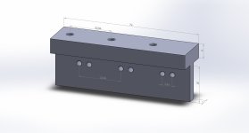
I just got my power-PCB kit as well, nicely packed with marked components. Happy! Now I have to reserve time for the assembly and a solution for the MOSFET cooling has to be found. Looks like an 'L' Alu-bar with a thickness of 5mm and a length of ~77mm would be ideal, 25-35mm wide on the FET side and 39mm on the other side. FET attachment with M3x8mm bolts, so that the threads don't come out on the other side of the cooling bar damaging the neighboring FET.
 
I'm sure you guys will get to assembly before I do, but I'm happy to mill something and send it out. I don't have time to design it, but can throw it in the machine queue no problem.
 
[youtube]sVL_4r5SyCs[/youtube]

This is an update for arber333 but i just wanted to post it here and show that soon there will be a 4th smd lebowski brain out in the wild. This one is to go in something bigger than a bike i believe. good luck Arber.
 
Is there any reason we can't mount the brain board on top of the controller instead of below, as long as there is clearance?
 
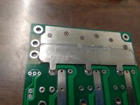
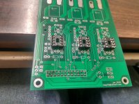
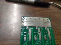
I made the slightest bit of progress today, feels good! Please excuse the hackish nature and poor soldering.

The extra plate is a little over 1MM thick, with a cross sectional area of 13mm^2 or so. Should be good enough? I hope I got it soldered well. I tinned the board, then tinned both sides of the plate, put flux on one side, and then progressively heated it from one side to the other, making sure the plate stayed flat. As you can see, a little solder squished out, so I think it is good.

rsz_1img_20180601_174516.jpg
rsz_img_20180601_174500.jpg
rsz_img_20180601_174535.jpg
rsz_img_20180601_174614.jpg
 
Thanks! If I end up ordering more of these, I may have the plates waterjet. Don't really lend themselves to milling very well. I just cut this one out with the bandsaw (hence the irregularity).

Do you think I'll have any issues with mounting the brain on top? Heat maybe? I already soldered the pins, but am thinking I'll reverse it. I desoldered the pins on the brain in preparation for it.
 
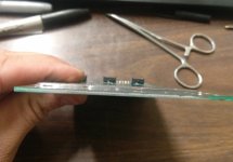
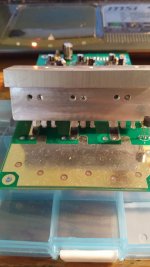
Designed and milled FET-to-case heat transfer block. FET mounting holes are M3 threaded and placed for each FET separately. Block+FET thickness is about 10mm, so if you add thermal pad and a washer then 10mm M3 screw is just perfect, without danger of protruding to another FET's belly.
FET cooler.JPG
20180603_115127.jpg
20180603_115043.jpg

Next up are 1mm copper plates for PCB traces.
 
Dont forget to electrically isolate the FETs from the heatsink (by means of little heat pads) !

Also make sure you have the high and low ohmic resistors connected to the battery input at the correct place. The high value goes in the battery measurement line(via the 100nF), the low value in the power supply line (via the 33uF) to the processor board. Try to drop voltage across the low value supply line resistor to end up with roughly 40V at the processor board supply (current flow is roughly 50mA, so resistor should be 20*the voltage drop you want, make sure the resistor can handle the power dissipation)
 
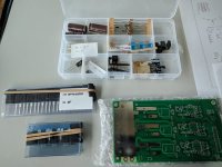
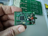
I got the nicely prepared kit for the power PCB from whereswally and a pimped brain PCB from lebowski. This brain is so tiny... almost the size of a post stamp. Now there's quite some work to do until it will be ready to be installed, here's my progress:
The kit:
IMG_20180602_154326_lo600.jpg
The tiny little poststamp-brain:
IMG_20180602_154440_lo600.jpg
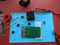
The soldering iron TS100 was recommended to me in the forum, it works much better than my other stuff:
IMG_20180602_165709_lo600.jpg
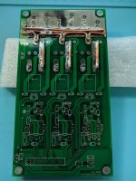
Tried to add copper to the traces, followed lebowski's example. This took me many hours... at the beginning all was good, but the more copper on the traces, the more obvious it was that a more powerful soldering iron would be needed:
IMG_20180602_181034_lo600.jpg
IMG_20180602_181051_lo600.jpg
Then I tried to mount the current sensors and the FET with the cut-off leg. The same problem: Not enough heat, skills, helping hands etc., the things are more glued than soldered:
IMG_20180602_184846_lo600.jpg
That's it for the moment, something between euphoria and frustration. The power limit is probably not defined by the design and the components, but more on my soldering skills...
By the way: whereswally included 22 ohm 'ON' resistors instead of the 15 ohm lebowski has found to be ideal. Would it be pedantic to buy 15 ohm (1/4 watts?) or can I leave them at 22 ohms?
And lastly: I admire minimum's perfect heat sink. Without proper workshop, this will be another hurdle for me... but all in all: Happy!
 
I have only a 50W iron, it just takes some time to heat everything up. Main thing to look out for is that the stuff on the opposite side of the board does not de-solder during this long heating time, so I had my L shaped heatsink there to keep things cool (clamped on with some clothes pins)
 
careful not to heatsoak those sensors, ive killed some before with too long on the soldering iron. I guess flux is your friend there. Good luck. Btw I pimped the brain board but granted with a lot of help from Lebowski, it is his code which is driving all this greatness. :p
 
The LM5017 is a 100v dc buck but I would probably keep it under 90v to be conservative. You can always power it separately from another buck dc supply and feed the brain 15v instead if you have to run high voltages
 
Progress! After about 16 hours I'm seeing light. Hoping so much that I didn't overheat stuff and I'm thinking about how to test it before applying juice.
IMG_20180617_180532_lo600.jpg
IMG_20180617_184056_lo600.jpg
Important remarks:
R1: According to lebowskis video one page back this resistor ("tbd") should reduce the battery voltage to around 40 V at ~15 mA. A voltage drop of from 80 to 40V would mean a resistor value of 2.7 kOhm. Value in the kit: 220 Ohm (just a 3V reduction). Is this ok?
R2: I think this resistor should be 39kOhm as results from lebowskis formula. In the kit is is only 39 Ohm (instead of kiloohm). Probably a critical misunderstanding, or is the misunderstanding on my side?
 
whereswally606 said:
[youtube]sVL_4r5SyCs[/youtube]

This is an update for arber333 but i just wanted to post it here and show that soon there will be a 4th smd lebowski brain out in the wild. This one is to go in something bigger than a bike i believe. good luck Arber.

Tnx for the kind thoughts.
Yes i am fiddling now with Ampera inverter. One 3ph bridge will be powering the Leaf motor with a different brain. But second power bridge will be able to run generator in sensorless mode. Also the small power bridge will power AC compressor hopefully in sensorless also.
That is the plan, implementation is some way however. I did have Ampera inverter interface made, but i made some mistakes in pinout, so i have to redesign. I will test on my original board... Photos follow.

A
 
emmgee said:
Important remarks:
R1: According to lebowskis video one page back this resistor ("tbd") should reduce the battery voltage to around 40 V at ~15 mA. A voltage drop of from 80 to 40V would mean a resistor value of 2.7 kOhm. Value in the kit: 220 Ohm (just a 3V reduction). Is this ok?
R2: I think this resistor should be 39kOhm as results from lebowskis formula. In the kit is is only 39 Ohm (instead of kiloohm). Probably a critical misunderstanding, or is the misunderstanding on my side?

50 mA , i would use a bunch of series connected .5W 100 Ohm resistor (or 2 of 0.25W 220 Ohm in parallel) for every 5V to drop.

The battery measurement resistor must be high, so definitely 39 kOhm or something of that order.
 
Thanks a lot bas, this is very helpful for all the builders and whereswally's cool kit.
So this looks like a 1kOhm 0.5W resistor for R1 (or 2 x 2kOhm 0.25W in parallel) for a 20S 84V setup, 220 Ohm is definitely not enough.
I replaced the needed 39kOhm for R2 instead of the 39Ohm in the kit.
 
Watch out, the power rating values are only correct for the 100 Ohm example... with 50mA and the voltage you want to drop you can calculate the required rating. 40V and 50mA means you dissipate 2W, the resistor you use should be able to take this . When using 100 Ohm 0.5 W resistors for instance, you need 8 in series for 40V, the 2W dissipation will divide itself equally ove the 8 resistors (so each one will dissipate .25W, well within the 0.5W rating)
 
Back
Top