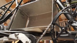
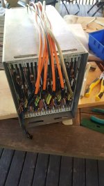
Hub Motors for Cargo Bikes

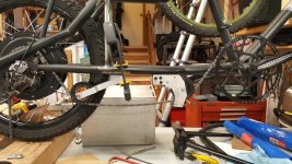
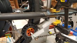
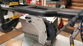
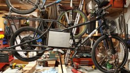
Raisedeyebrows - I'm not even close to giving up yet - super excited to get this grocery/beer/people hauling beast up and running! I ended up deciding to keep all the cells and just have a slightly compromised chainline, which is not an issue as I'll only be nominally pedaling and don't mind replacing a chain every 500 miles or so.It's not bad when I'm in the top 4 gears, it's only when I use the first few gears that the chain bends like crazy and in these cases I'll be limping home with a dead battery/mechanical failure so I'll just move the battery to the side to make room for the chain temporarily.

Amberwolf - you literally just summarized the past few days of my thoughts on the matter - ended up settling on a "simple is better" view on it and am going to use chaintube to try to keep the noise down.

It was a toss up between the top chain line with a custom pulley, or the bottom one and some chain tube. I'll try my luck with the chain tube and move to more drastic measures if the chain wear is too much:

image2001.jpg

Cheers!
 
Knowing how the long wheelbase makes mine such a fun bike to ride through windy corners even with 26" wheels I can imagine your's will be even more fun to corner with the 20" wheel and a bit lower center of gravity. The long wheelbase makes them feel kind of motorcycle ish. Some of you guys sure have some nice cargo bikes, always enjoy seeing them, that is an impressive battery pack you've got there. I hope you can get it completed soon, good weather is coming!
 
Now that I have the chain line figured out, it's on to the wiring, which, like everything I do, is going to also be more complicated than needed...

I've thought about using anything from 4P3T switches (is there one that does 60a continuous?) to connecting a bunch of 3ph disconnects together, the continuous amps will be 60A. The basic idea is to have 4 modes:

Fast Mode (ludicrous speed?): all 20 cells are wired in series, and a contactor is turned on to turn on the controller. (range should be around 60 or 70mi with a cruising speed of just over 36mph)

Slow Mode: (2) 10s packs in parallel to half the voltage and double the AH (range is calculated to be ~200mi with this setup at 21mph cruising speed)

Off Mode: Batteries disconnected

Charge Mode: Cells separed into (2) 10s packs to do periodic balancing charging, since I don't know of a balancing charger that does 20s. I don't want to mess with cheap BMS, I would like to use a hobby-style charger like my 1010b.

Any ideas?
 
mechanix said:
Fast Mode (ludicrous speed?): all 20 cells are wired in series, and a contactor is turned on to turn on the controller. (range should be around 60 or 70mi with a cruising speed of just over 36mph)

Slow Mode: (2) 10s packs in parallel to half the voltage and double the AH (range is calculated to be ~200mi with this setup at 21mph cruising speed)
You get the same range no matter which way you wire them, because you get the same Wh total. (assuming that in neither mode are you exceeding the C-rate capability of the cells, so they don't sag much in voltage and waste power as heat).

The difference is in how you use that power. If you go faster, it'll use more power to counter the air resistance. If you accelerate faster, especially with more weight, and do that more often, you'll use more power.

As long as you can control your throttle hand, you have no need to switch the batteries themselves around, which has a bunch of disadvantages and not really any advantages I can think of that aren't better done in some other way.

--more wiring to have something go wrong with

--more resistance and more inductance in the wiring, which reduce the performance of the system

--more contact resistance from the switches (though you'd have at least half the same resistance if you have a switch at all, like for power cutoff)

--a single point of failure that will end a ride (or prevent one) if the switch fails (just one bad contact makes the whole thing fail)

--the controller must be able to operate on a VERY wide voltage range, and it won't be able to have an LVC to help protect your pack, at least not in the "ludicrous speed" mode. (you'll have to depend on your BMS to shutdown based on cell-level LVC and that means running cells *really* low before that happens, which is harder on them, as many BMS have really low LVCs--since you don't want to use a BMS, it means you have NO pack protection at all).

--Or else you'll have to have two controllers for each motor, wired in parallel, with switches on their phase and battery wires to disconnect or connect them, ganged together with the battery voltage switch. (and this adds even more performance-degrading resistance/inductance and more complex wiring, more stuff to fail).

--Switches to do what you want at the current and voltage you're after are large and can be expensive. Sometimes you can gang multiple singlepole switches to create one that has enough poles, which will probably be (a lot) cheaper, but it might be physically larger when you're done, and there's a potential for timing differences due to teh ganging that cause make-before-break problems (whereas you need them all to be break-before-make to prevent shorts and fires).

--If you get a switch not rated for the peak DC voltage, there's the chance that when you switch modes (especially under any load, as unlikely as that is to happen) it'll continue arcing across the contacts and fail to shutoff, never breaking part or all of the previous connection, and then as the switch moves to make the next connection, it's now shorting across part or all of the pack, and you now have a fire as the wires and switch become extremely low resistance heaters.

--I've probably forgotten other disadvantages....


If you can't control your throttle hand or have some other reason to have a lower-speed mode, it's easy enough to setup something to limit speed when you don't want to be able to go fast, either in the controller with a 3-speed switch and programming it to whatever you prefer, or using osmething like the Cycle Analyst from Grin to do this for you.

Even a simple physical stop on the throttle, like a pin you can insert or a mechanical cam you can rotate into place, to prevent it going any further up than halfway (or wherever) for the lower-speed-limit mode, but when disengaged allows full throttle for ludicrous mode.

Eliminating the switch in voltage also eliminates the need for a "charging" position in the switch, too, so you can just have an "off" switch, which only needs to disconnect either positive or negative but not both (unless you just really want to). It's a LOT easier to find a suitable single-pole single-throw switch of a size you can fit on the bike and a cost you can fit in your wallet. ;)

For charging, you can simply use two 10s balancing chargers, and plug one into the "top half" of the pack, and the other into the "bottom half" of the pack. As long as they are isolated, this will work fine. If they are not isolated, then put your "off" switch *between* teh two halves of the pack, so charging is done only when in "off" mode, and then there's nothing to short between halves.
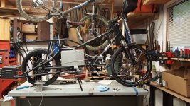
 
AW - Thanks for all the info, you've saved me a lot of work, and I'm sure my installation will be much cleaner (and lighter, less expensive, more reliable, etc...) by using the Cycleanalyst I already have on hand to do the speed limiting. Sometimes I get tunnel vision and am so focused on finding a solution that I forget the reason I was doing it in the first place. One good indicator when I'm going in the wrong direction is not being able to find the correct parts (maybe there's a reason a 4P3T 80a switch doesn't exist! Answer: it shouldn't except maybe in some industrial application!)

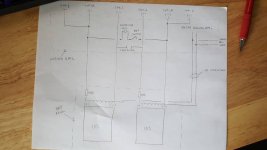
Here's a rough sketch of what it will look like:

image2001.jpg

Am I missing anything major?
 
Couple questions:

--I might be missing something, but what completes the circuit for the contactor coil/keyswitch, so current can flow thru it? If I'm reading the diagram right, the packs are only connected to each other (completing the circuit) if the keyswitch is already on and the contactor is already closed, but the coil cant' get any current to close the contactor until the packs are connected to each other.

If I'm reading it correctly, then you can fix this by powering the coil by only one of the two packs; that pack will simply have a bit longer charging time on every cycle than the other one does to make up the difference.


--Does your contactor have a coil that runs on your full pack voltage? Or at least half of it? Most I've seen in person are 12v or 24v coils (though that's not very many). If your contactor isn't designed for that voltage on it's coil, you'll have to use a DC-DC that's powered by one of the two pack halves to downconvert to the coil voltage. Then the keyswitch won't switch the coil directly, it will instead switch the power to the DC-DC, and the coil runs directly off of that.

-- the "cellog / bm" lines: Are they going to be connected to those all the time, for cell-level monitoring during a ride? Or only when balancing (I'd expect your 1010s would do that, so anything else isnt needed) during a charge? If the former, that's a fair bundle of wires to run all the way up to your handlebars, with risk of wire breakage/short/etc, so I'd fuse each wire with a *VERY* tiny fuse right where it comes off the cell. You can then more safely use something like an old parallel printer cable or SCSI cable, which may have up to 26 conductors (if it has a separate shield ground) in a very thin gauge of wire (won't need any real current in them if you're not doing the balancing with them, only voltage monitoring).
 
mechanix said:
Sometimes I get tunnel vision and am so focused on finding a solution that I forget the reason I was doing it in the first place. One good indicator when I'm going in the wrong direction is not being able to find the correct parts (maybe there's a reason a 4P3T 80a switch doesn't exist! Answer: it shouldn't except maybe in some industrial application!)
FWIW, Ive done the same kind of thing; usually I let things stew a while before committing work to it, and then realize a much simpler way exists, and then I actually do it that way.

Sometimes I'm constrained by the parts I have, and so I'm stuck with teh complex way until I run across the bits to do it the other way.

One example is the stuff I'm going to have to do to make the TorquePAS / etc work the way I want them to on the SB Cruiser trike, because teh CAv3.1 can't yet do it. Right now theres about 5 or so separate electronics modules I have to design and build to do the various functions; no idea how long that will take or when I'll get started on it--it's still stewing in the back of my mind. I'm hoping a simpler way will pop up, but probably not in this case.
 
AW -

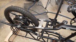
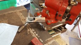
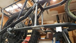
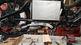
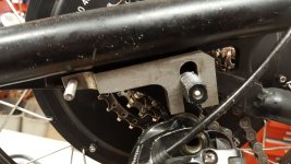
Good find on the pack wiring! I finally got around to working on it some more, it's really slow going. I had to re-route the chain around the battery, which required reinforcing the frame because the forces from pedaling are no joke!

image2001.jpg

Practice:
image2002.jpg

Finished welds:
image2003.jpg

More to come, I have all day today to try to finish this!
 
Decided to redo the front mount for the pulley, I didn't like the thin side plates:

image002.jpg

Torque arms:

image001.jpg
 
I anyone's still reading this, I've got a question for you:

I only have (3) Cellog 8m's and I can't seem to get ahold of an additional Cellog for under $80 - Is there an easy way to use (3) of them to monitor the 20 cells? I only need them connected when I'm riding, just for low voltage monitoring. I was planning on using (4) of them with (2) on each side of the split on the pack.

Cheers!
 
There is more than one version of the cell log (don't remember the model numbers) including one that stores info to be read by USB later, and one that doesn't. If you don't need the USB and just need to monitor live on the "dashboard", the latter is cheaper, and theres a number of other devices that do the same thing (dunno if they're the same size/readability).

Google comes up with the Progressiverc site as the first hit for the cell log, and each model they list as discontinued shows another device that they recommend for the job, if it helps. I didn't look at the alternates, so don't know if they'll do the job or not.

Hobbyking also comes up, and probably has similar stuff.


https://www.google.com/search?q=cell+log&ie=utf-8&oe=utf-8

https://www.progressiverc.com/celllog-8s.html

https://www.progressiverc.com/celllog-8m.html


The Battery Medic will also display individual voltages live, though it doesn't record anything. (can also balance). Not the most accurate but tehy're generally consistent within a batch, from reports on ES. I only have one, several years old, I use it to check cell voltages in testing of packs / cells when I need to see more than one at a time. There's a number of clones of the BM around, and some are better than ohters, so you might poke around ES for info/links to the better ones.
 
A few more update pics, can finally pedal it, man this this is a pig on anything more than 2 degree slope!

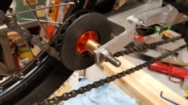
The rear pulley was having a hard time sliding left and right when shifting gears, so I put a bronze bushing to help it out. works great so far!
image2001.jpg


image2002.jpg

image2003.jpg

image2004.jpg
 
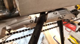
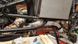
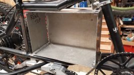
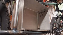
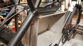
Got some more work done on it this weekend, mostly on the mounting brackets for the battery box. Clearances are tight!

image2001.jpg

image2002.jpg

image2003.jpg

image2004.jpg
 
Going to use copper pipes cut in half then pounded flat:


Getting closer! I feel like a weekend dedicated to it and I can actually ride it!
 
10mm stainless button head with nylock nuts. Planning on using anti oxidation compound because I'm not sure how the stainless reacts with the copper. I'm open to better suggestions, though.
 
I just wasted 5 hours of my life looking for a switch for this bike...is there not a standard solution for this yet??? My battery pack will be 80VDC hot off of the charger, this is what I'm thinking I'll need to switch this on and off safely and reliably:

-10W ~500ohm resistor
-80V 100A contactor (best case would have an economizer circuit to reduce current drain when coil is energized)
-Some kind of key/rotary switch
 
mechanix,
I am interested in your battery bild, it looks like you are using LEAF 31Ah cells?
I built 11S Leaf cells pack for my Eplus bike, charge to 4.00V/cell only.
for 43V fresh off charger I use 50A rated switch by NKK MADE IN JAPAN.
BOUGHT from DigyKey, not cheap of course, min 35USD.
I am wondering you never consider soldering tabs?
I solder but now I regret, your way is better, no torture with high temperature.
 
miro13car,

I believe they are the new 41ah cells, and yes, I didn't solder them because I would worry about the heat getting to the cells. And soldering is so permanent, I'd like to be able to reconfigure the cells down the road if my design changes. I've already changed my design about 100 times during this project....
 
I've got a question about the power supply I was planning on using for my two iCharger 1010B+

-Are the outputs isolated? I will be charging the whole 20s setup in two separate groups of 10s, and would like to not have to physically disconnect the two groups before charging.

-I found two pots and wanted to make adjustments to get a few more volts from the system - none of the pots seemed to make any difference on the top 3 small power supplies, but I just barely turned the right-hand pot on the bottom big power supply and it went from 12v to 6v and now nothing I do makes any difference...did I just ruin the power supply?

 
mechanix,
so you pulled those cells from 8-cell Leaf modules.
On my discharge tests using CBA I didnt even come close to say 35Ah leave alone 41Ah , so I believe they are 31Ah cells.
 
Back
Top