Cooling fans inside Hub motors

I just found this thread, quickly zipped through the pictures and thought I might as well post my variation. I came up with this a little while ago out of the blue to solve forced air cooling and had no idea that many other people had done the same thing. Oh well...I guess great minds do think alike.

I have 3 hubs I want to force ventilate like this.

People have shown a diagram where the intake side has the air separator and the exhaust side does not. I came up with virtually the same thing on my own, but I separate on the exhaust side.

1. Drill holes in a ring towards the center of both covers and inline with the ducted fan exhaust side.
2. Put a ducted fan in between the spokes inside the hub as has been shown previously.
3. Attach a shallow bowl shape to the exhaust side of the fan that covers all of the exhaust holes. Position it very close to the inside of the side cover. The idea is to have it close enough that you get 90% air flow out of the shell and only a little leakage back into the motor cavity. The smaller the gap between the bowl covering the exhaust holes and the shell side the better! But obviously they can't actually touch.
4. Create an internal duct that redirects the suction side of the fan into the exhaust side of the motor through another internal spoke hole.
5. Close up any remaining internal holes through the motor.

The effect is you draw air in from one side of the hub motor (intake side). There is no air flow path except through the stators and magnet gap at the perimeter of the motor since all other air flow paths are now blocked. You get lots of swirling air inside the intake side of the motor picking up heat before it passes through the stators. Air is sucked through the stators and into the exhaust side of the hub motor. It is then redirected through that duct and into the intake side of the fan. Hot air exits the exhaust side of the fan and out through the bowl and exhaust holes. In theory, the intake side will be all cool air coming in, sucked through the stators and magnet gap and then into the blower and out the exit holes. There won't be any dead air space inside the motor since the entire internal space of the motor will have air flow through it, but will be forced through the stators since that's the only air flow path. Air flow will have little choice but to enter near the center on one side of the motor, be sucked through the stator teeth and exit on the other side of the motor near the center.

Here's a quick sketch of my idea...and of course I missed something...close off the area around the fan so air can't go any direction but through the fan.

Hub%20motor%20internal%20blower.jpg


And a few close-ups since it's not so easy to see...

2018-07-10%2017_51_45-Hub%20motor%20internal%20blower.jpg%20-%20Windows%20Photo%20Viewer.png


2018-07-10%2017_52_37-Hub%20motor%20internal%20blower.jpg%20-%20Windows%20Photo%20Viewer.png
 
TBH I would start with a simple design like I have done where you just suck air in one side and blast out the other. Straight through so to speak.
It may not be as effective, but if it's effective enough it will save a lot of complex engineering compared to what you have in mind currently.
The key is to position the vent holes right next to the windings. That way the air flow still moves past the windings taking a lot of heat with it and it doesn't matter that you force air through the magnet gap etc.

Just a thought before you spend a lot of time/effort on something that may not ultimately be necessary.

Cheers
 
Cowardlyduck said:
TBH I would start with a simple design like I have done where you just suck air in one side and blast out the other. Straight through so to speak.
It may not be as effective, but if it's effective enough it will save a lot of complex engineering compared to what you have in mind currently.
The key is to position the vent holes right next to the windings. That way the air flow still moves past the windings taking a lot of heat with it and it doesn't matter that you force air through the magnet gap etc.

Just a thought before you spend a lot of time/effort on something that may not ultimately be necessary.

Cheers

If I put holes right by the stators on both side plates, that will create air flow over the sides of the windings, but not necessarily through them. Air will have to exit next to the other side of the stators. It is simple, but does it pull away enough heat?

I have a brand new 4kw QS motor. It's been sitting on the shelf for a year now waiting for me to "get around" to implementing it.
http://www.qs-motor.com/product/10inch-4000w-v3-type-e-scooter-hub-motor/

I plan to run it at 10kw or whatever the reasonable maximum is I can get out of it. I've engineered lots of stuff in my garage over the years. An optimal air path through the motor won't be a problem. I do believe in the KISS principal...if at all possible. However, I really want to get the air forced through the stators and magnet gap and not just blown by them.

I also have a hubmonster. It's a 6 phase motor and I've read that people push 30-35kw out of it. I'll be forced air feeding it too...somehow. It will see the light of day before the QSmotor does. I'm already in progress on this build.
 
Well I guess it all depends on how far you want to push it.

In my case I've been able to run my '1500W' Leaf motor at 5-6KW with reasonable performance. My 2KW HS4080 is also fine running at the same power levels and has a little more thermal headroom.

Also my old HS4060 that had variable speed fans was able to push 6-7KW with the fans maxed out.

So I guess you can get 3-4 times the stock performance when using the simple 'straight through' forced air approach I've taken. Offroader will need to confirm, but I think the method he took was able to go higher than that, but with the obvious added complexity.

As a point of comparison, I'm also pushing 13KW through a MXUS 3K on my Alpha with FF and Heatsink cooling. It doesn't cool off as fast as the forced air method, and it heats up fast going up steep hills, but it's silent and simple compared to my fans. I'm also still tuning that motor so part of the heat could be from that.

Cheers
 
ElectricGod, I'm going to try and figure out your design and will report back.

My design works very well and is very reliable, I really think I could have one of the best cooling modification made to a hub motor considering the high airflow I can use. I just need to make a 3d print part to exhaust the air to the other side of the motor so I do not suck in intake air. If I make that simple part that fits on the exterior of my hub motor, my cooling solution would blow 80%+ fresh air through the motor constantly, that is some serious cooling at the high speed air flow the 40mm EDF fan I use can blow through the motor.


So far I can not understand how you can exhaust air on the one side of the motor without also sucking it in through that same side.
 
Offroader said:
ElectricGod, I'm going to try and figure out your design and will report back.

My design works very well and is very reliable, I really think I could have one of the best cooling modification made to a hub motor considering the high airflow I can use. I just need to make a 3d print part to exhaust the air to the other side of the motor so I do not suck in intake air. If I make that simple part that fits on the exterior of my hub motor, my cooling solution would blow 80%+ fresh air through the motor constantly, that is some serious cooling at the high speed air flow the 40mm EDF fan I use can blow through the motor.


So far I can not understand how you can exhaust air on the one side of the motor without also sucking it in through that same side.

That's where the bowl shaped part comes in. It is the isolator between the exhaust air and actively circulating air. It's lip sits right next to the exhaust side cover. A little air leaks around it and back into the motor, but 90% of the air is pushed out the exhaust holes in the side cover. The fan output side flows into the bowl. I should do a better sketch. What I posted above was done in a couple of minutes when the idea hit me.

You use silicon on the sides of your stators to act as "near seal". I'm using the lip of my bowl shaped part which sits very close to the inner wall of the side cover to do the same thing.
 
Yes I see what you mean, It is a workable solution that solves the problem of sucking in hot air. As long as you can get enough holes on the exhaust side to not limit the airflow. I know that I had to keep drilling my holes bigger and more holes when I saw just how much a difference it made to increase the hole sizes to get a better air flow.

Because you are forced to put the side cover holes closer to the axle, you will weaken the side cover much more than having the holes at the edges of the side cover near the spoke holes. I would have to see how you work out the duct/bowl and where it touches the side cover.


The silicone is worth using, at least a little of it to seal the side cover to your bowl. This way you mold as tight a fit as possible. You could never made a bowl that sit flush enough without some kind of moldable seal.

I like it, do you have any idea what EDF you will use? I recommend that aluminum 40mm one, that is by fat the best you will get if you could fit it.
 
Offroader said:
Yes I see what you mean, It is a workable solution that solves the problem of sucking in hot air. As long as you can get enough holes on the exhaust side to not limit the airflow. I know that I had to keep drilling my holes bigger and more holes when I saw just how much a difference it made to increase the hole sizes to get a better air flow.

Because you are forced to put the side cover holes closer to the axle, you will weaken the side cover much more than having the holes at the edges of the side cover near the spoke holes. I would have to see how you work out the duct/bowl and where it touches the side cover.


The silicone is worth using, at least a little of it to seal the side cover to your bowl. This way you mold as tight a fit as possible. You could never made a bowl that sit flush enough without some kind of moldable seal.

I like it, do you have any idea what EDF you will use? I recommend that aluminum 40mm one, that is by fat the best you will get if you could fit it.

NO idea about an EDF yet...was actually hoping for suggestions. Where do I find what you are using?

I want the bowl locked to the spokes inside the motor. It will get sealed in place around the EDF outlet. I'm sure if I buff the inside of the side cover to a glossy shine that I can put some kind of felt or rubber seal on the edge of the bowl to keep the exhaust air from leaking back inside the motor. The vent holes can really be anywhere. The diameter of the bowl can be whatever fits the space and doesn't block internal air flow.
 
I'm going to do some planning and to see if your method would work on an MXUS turbo. I understand how you want to do it but have to work it out and see if it is a better design than I have.

I don't like how my intake and exhaust are both on the same side, while this does work to cool my motor well, it may not be very efficient. The fan is so powerful that it really sucks lots of hot air back into the motor.

I recommend this EDF if you can fit 40mm diameter. You may not be able to do this with a QS motor. It does work with the MXUS turbo with slight filing.

https://hobbyking.com/en_us/dr-mad-thrust-40mm-8-blade-alloy-edf-8000kv-motor-330-watt-3s.html

This 40mm edf is by far the best solution out there because it is built well, small, handles a lot of power. I run it on average about 6 amps at 12 volts. You would need an ESC and a DC/DC power supply to run it.

You could of course use smaller EDF fans, but they will be plastic. You may even be able to cut the 40mm edf fan housing to fit it into a smaller spot. Possibly even buying a propeller and motor may also be sufficient.
 
Offroader said:
I'm going to do some planning and to see if your method would work on an MXUS turbo. I understand how you want to do it but have to work it out and see if it is a better design than I have.

I don't like how my intake and exhaust are both on the same side, while this does work to cool my motor well, it may not be very efficient. The fan is so powerful that it really sucks lots of hot air back into the motor.

I recommend this EDF if you can fit 40mm diameter. You may not be able to do this with a QS motor. It does work with the MXUS turbo with slight filing.

https://hobbyking.com/en_us/dr-mad-thrust-40mm-8-blade-alloy-edf-8000kv-motor-330-watt-3s.html

This 40mm edf is by far the best solution out there because it is built well, small, handles a lot of power. I run it on average about 6 amps at 12 volts. You would need an ESC and a DC/DC power supply to run it.

You could of course use smaller EDF fans, but they will be plastic. You may even be able to cut the 40mm edf fan housing to fit it into a smaller spot. Possibly even buying a propeller and motor may also be sufficient.

Thanks for the info!

Ever mess with qauds or heli's? Open props, wing tips, any lifting surface has spoiled air over the tips which reduces it's lifting ability and efficiency. You will notice a lot of air planes have an upturned tips on the ends of the wings. This is to stop air spoilage from reducing lift. A cowled fan does not suffer from this issue and it also isolates air flow to inside the cowling. Wiring sitting nearby can't get tangled in the fan either. An EDF is the best choice IMHO.

Your design of having intake and exhaust on one side does have an advantage. One whole motor side wall is uncompromised by holes in any way. I think I could make my bowl design work on a single sided system and it would eliminate the internal air redirection through a duct. The bowl would do all the air flow isolation. I'll have to think about that some more and come up with a drawing.
 
Ebay is great for finding ideas for things and for products from everywhere on the planet.

I found that same EDF on ebay for double what HK sells it for...LOL!

https://www.ebay.com/itm/400G-THRUST-3S-DR-MAD-THRUST-40MM-8-BLADE-EDF-8000KV-330W-RCLANDER-SUBSTITUDE/322811625051?hash=item4b29127e5b:g:30cAAOSwna1Z2Eqz
 
ElectricGod said:
Ebay is great for finding ideas for things and for products from everywhere on the planet.

I found that same EDF on ebay for double what HK sells it for...LOL!

https://www.ebay.com/itm/400G-THRUST-3S-DR-MAD-THRUST-40MM-8-BLADE-EDF-8000KV-330W-RCLANDER-SUBSTITUDE/322811625051?hash=item4b29127e5b:g:30cAAOSwna1Z2Eqz

Hobby king gets those in stock every so often and you need to buy them fast when they are in stock. You have to be notified when it comes in stock and buy it as soon as you get the email. I found they sold out within a couple of hours.

If you are in a pinch and can't wait, the $49 on ebay is not so bad, they basically buy them from hobby king and resell them.

After this EDF worked for me I bought 2 spares some time back.

With the open propeller, yes you would have to build your own duct around the propeller or is it an impeller, if you couldn't fit the 40mm EDF.
 
Hi Guys :)

I'm lurking ad learning mostly atm, but found all the 'Active Fan Cooling talk here and elsewhere interesting.

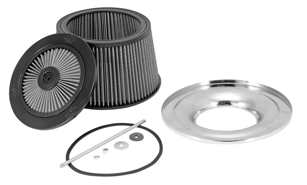
So... my reason for necroing this thread is this flat bit (on the left in the pic) of a K&N Air filter which may fit in or on a drilled hub side cover? or be made to fit..?
https://www.knfilters.com/blog/kn-drag-racing-air-filters-increase-performance-and-airflow

66-3340R_Exp.jpg


The idea being; to filter out dust and grit etc, with a filter that is designed to be oiled as part of its makeup.

I have successfully sucked air through a std car filter in a modded computer case, so know that car filters work with fans, so have every confidence that a high flow filter made from oiled cotton fabric material, similar to medical-grade gauze, will work.

So if anyone happens to be riding past a K&N stockist; going in and having a look and chat might be worthwhile..?
There are no such stockists here for me to visit. (South Africa)
 
Logic11 said:
Hi Guys :)

I'm lurking ad learning mostly atm, but found all the 'Active Fan Cooling talk here and elsewhere interesting.

So... my reason for necroing this thread is this flat bit (on the left in the pic) of a K&N Air filter which may fit in or on a drilled hub side cover? or be made to fit..?
https://www.knfilters.com/blog/kn-drag-racing-air-filters-increase-performance-and-airflow

66-3340R_Exp.jpg


The idea being; to filter out dust and grit etc, with a filter that is designed to be oiled as part of its makeup.

I have successfully sucked air through a std car filter in a modded computer case, so know that car filters work with fans, so have every confidence that a high flow filter made from oiled cotton fabric material, similar to medical-grade gauze, will work.

So if anyone happens to be riding past a K&N stockist; going in and having a look and chat might be worthwhile..?
There are no such stockists here for me to visit. (South Africa)
I explored filters back in 2017 from memory...probably back in this thread somewhere. I was thinking of using coffee filters at the time as they would be a good fit for the holes drilled in the hub covers.

If it did work, while it would help keep the dirt/dust out, unfortunately I am pretty sure it would restrict air flow to the point that it's not worth it compared to the Ferro Fluid + Hubsinks.

As it is, I would guess a good fan setup is only about 20-30% better than FF + Hubsinks while moving and 40-50% better while stopped. Adding filters will probably make it about the same at which point you may as well just use FF + Hubsinks as there is no dirt/dust problems and no filters to clean.

Cheers
 
Back
Top