Fuse-wire for individual cells, DIY Tesla style

Addy said:
EbikeAus said:
I have used the axial glass fuses, they are generally low amp but they do contain the burnt fuse material and you can see when fuses are blown...if you use clear heat shrink as I do.

Are you referring to the kind of fuses that I tested here https://endless-sphere.com/forums/viewtopic.php?f=1&t=93472&p=1367786?

I would avoid using those firestarters and stick with fusible wire.

I much prefer fuse wire, which is what I exclusively use now.

The glass fuses are a PITA to install as well.

Having said that, people are using them successfully but mainly in diy powerwalls, not ebike packs.
 
Fuse wire and mentioned glass fuses are less then ideal for discussed job.
Ideally it should be:
1)low heat conducting material with
2)high current conductivity,
3)confined fusible area and
4)protected fusible area

What comes to mind is following fuse design with fine, zink based fusible link
sku_70667_2.jpg


EbikeAus said:
Any update on that idea Parabellum?
No, the N4 requirement is not met.
 
1 is enough. Prefrably heat shrink with glue.
 
I looked up the composition if fusible wire once, and it was almost identical to lead-free solder (tin/zinc alloy) Heat shrink would work to contain splatter, especially since clear heat-shrink exists to allow visible inspection...maybe shrink the two ends and leave a bubble in the center.
 
One layer is enough, especially if you use glue. That will keep the glass in place when it shatters and absorbing the force. They also do this in regular commerical stuff where they just have a fusable resistor or something.
 
It's not getting hot enough to melt the glass, the fusible conductor inside the glass gets hot enough to melt, but that heat is dissipated over the much larger area of the glass tube. I don't think it will get hot enough to burn the shrink tubing.
 
I'm not saying that the Chinese glass fuses are bad or useless, but...I don't trust their ratings. I feel if the fuse is getting that hot in normal use, then the current rating is too low.

I think the way to spec a fuse is to carefully consider the normal use compared to the expected failure mode.

If your concern is an internal short on one cell would cause the entire P-string to short. Then the max amps of the entire P-string is roughly triple the amps needed to blow the fuse. (*slightly more than your single-cell max drawn amps?)

This is because if the fuses are too small (even if they are not blowing at your peak pack amps) then...they are acting like resistors. Converting some of your current into heat, causing voltage sag. (*just my opinion).

it would be nice to be able to buy a variety pack, so I can test them to failure, then order what worked, regardless of what the rated spec on the label said...
 
Another issue with the small fuses I tested would be the interrupting capacity. Proper fuses have ratings for interrupting capacity, which is the maximum current where the fuse will still be able to break the circuit. With high current faults the fuse wire will melt quickly, but inductance in the circuit can cause an arc within the fuse which will continue to carry the fault current of the circuit.

Good fuses are designed to have large distances that an arc would have to travel, to make it difficult for small arcs to survive. Some fuses are filled with sand, which melts into glass when the fuse blows and blocks the path that an arc would take.

I suspect that the tiny chinese glass fuses would not have a high interrupt capacity because the internal volume of the fuse is quite small. It's possible that once you have enough current to blow these fuses quickly, the fuse might not be able to interrupt that current anyways.
 
Addy said:
I suspect that the tiny chinese glass fuses would not have a high interrupt capacity because the internal volume of the fuse is quite small
Remember, you have to interrupt <4.2V circuit and only a dozen or 2 of A current capability. That is not really a plasma danger level and discussed fuses have at least 5mm gap capability.
 
Addy said:
parabellum said:
Remember, you have to interrupt <4.2V circuit and only a dozen or 2 of A current capability.

This depends on the specifics of the battery pack it's used in. With many parallel cells the fault current could get quite high if a single cell were to develop an internal short.

1) The fusible link will be interrupted/fused before real current flow can build up.
2) Internal short is not exactly a dead short, like throwing a wrench on the terminals. The cell will not develop a copper nail inside, but for sure you can hammer one in lengthwise, but again, look N1.
We could ask OP to sacrifice one fuse shorting it on high discharge 1s LiPo cell, to be sure.
 
parabellum said:
2) Internal short is not exactly a dead short, like throwing a wrench on the terminals. The cell will not develop a copper nail inside, but for sure you can hammer one in lengthwise, but again, look N1.
We could ask OP to sacrifice one fuse shorting it on high discharge 1s LiPo cell, to be sure.

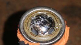
This is not the only way to develop a short though. I have witnessed an overheating cell which melted the separator on the positive terminal. The separator plastic got squeezed out and the positive terminal was now directly in contact with the cell's outer shell.

Certainly some more testing on these fuses would be helpful. When I have the time I would like to do some testing on fusible wire as well.
 
Addy said:
I have witnessed an overheating cell which melted the separator on the positive terminal. The separator plastic got squeezed out and the positive terminal was now directly in contact with the cell's outer shell.

This is what that looks like by the way:

20180112_135737.jpg


This was done on purpose to a dead cell to show what it looks like, by holding a soldering iron to it for way too long.
 
what cell was that shorted? all name brand cells i use have protection for overpressure built in and those trigger way before the plastic melts.
 
after my 4 yr old battery back went up in flames I am going to be doing this

a BMS wire got a wee bit too hot and was the 1 and only wire that sat across the ribbon cable
needless to say things started shorting


so whats the best fuse that can handle mountain bike bumps ...
 
you need to use proper cell holders, proper sized nickel strips and make sure the balance wires dont touch or cross and glue/tape everything down so nothing can move. then put the battery in some shock absorbing foam and strong case that can endure being trown around a mountain.

that way you wont get a short. i built dozens of mountainbike batteries and never had a single issue in the past years.
 
MasterCATZ said:
after my 4 yr old battery back went up in flames I am going to be doing this

a BMS wire got a wee bit too hot and was the 1 and only wire that sat across the ribbon cable
needless to say things started shorting

Individually fused cells may not prevent a fire if the balance wires short out. Those little wires will smoke and start glowing before the fuses will blow. I've seen packs where each balance wire is fused at the pack, but this would be a lot of extra work.

As flippy points out, arranging the wires so they don't cross or pinch against the cells is the best way to prevent this.
 
it was a manufactures battery pack that caught fire


how ever I believe I hit another snag , with the new pack being 16s5p , I don't have enough P to flow 40 AMPS through 5x 1 AMP fuses

so much for the motor only being 480 watts it spends most its time around 20 amp draw on the flat and almost 40 AMPS up hills

explains why it kept melting 20+ AMP fuses


so I was thinking I need a way to NOT have all the AMPS flowing through the battery cells would it be possible to add in a diode on each string to off load the current directly back to the bus bars ?

I don't think the BMS will do anything but charge the pack ?


the cells are ICR18650-26F I was going to put a 1 AMP fuse on each cell

Nominal Capacity 2600mAh (0.2C, 2.75V discharge) Standard charge: 1300mA Max. Discharge Current 5200mA

I know the cells are crap but I have 3x 13s4p battery backs here I can raid the 80 cells from ( 1 brand new was DOA )
 
MasterCATZ said:
so I was thinking I need a way to NOT have all the AMPS flowing through the battery cells would it be possible to add in a diode on each string to off load the current directly back to the bus bars ?

the cells are ICR18650-26F I was going to put a 1 AMP fuse on each cell
If your pack is assembled correctly, no single cell will flow more than its share ..maxAmps/P ..of the current.
For your 40A draw on a 5 P pack, each cell will discharge (flow) 8 amps max.
If you are going to use individual cell fuses , they will need to be rated higher than 8 amps.
The bus bars should be the only items seeing the full 40 amps.

But remember, Tesla, who developed and refined this fuseed cell system, together with many other monitoring and safety systems, have still had random pack fires :shock:
 
my main concern is these batteries should not even be putting out his many amps to start with, as rated as 5amp max in a 4p setup which would have meant 20amps max and with my 5p setup 25amp max, bright side new BMS allows me to set the max discharge


unless I give up on the glass 1amp single cell fuses and go for PPTC single cell fuses around 5amps?

oh and the controller was only rated for 20 AMPS also explains why i have been through 4 controllers 3 motors and battery packs ...


its a rebadged Tonaro 48v 500w bike system
 
Back
Top